36
Chapter 6 - SAT Measuring Range
106 V3.2
DiSEqC
6.4.3
DiSEqC (Digital Satellite Equipment Control) defines a standard which transfers the control
commands from the master (e.g. receiver) to the slave (e.g. multi-switch, positioner) via FSK
(frequency shift keying of 22 kHz) on the RF cable. DiSEqC is backwards compatible to the
14V/18V/22 kHz control.
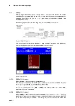
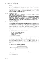
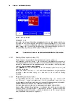
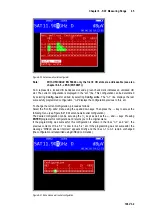
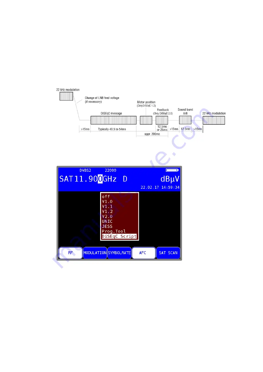
The following diagram shows the chronological sequence of a DiSEqC1.0 sequence:
Figure 6-9 DiSEqC 1.0 Sequence
The 14V/18V/22kHz control follows immediately after a DiSEqC sequence. This allows non-
DiSEqC compatible components to be run when DiSEqC control is active.
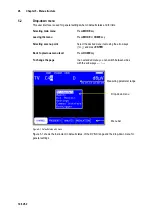
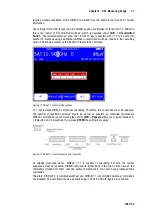
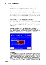
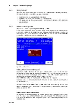
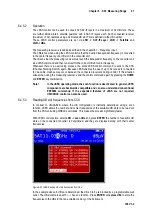
Figure 6-10 DiSEqC menu
6.4.3.1
DiSEqC V1.0 control
LNB
->
DiSEqC
->
V1.0
activates DiSEqC standard V1.0.
This allows up to 4 satellite positions with up to 4 SAT-IF layers each to be controlled. You set a
SAT-IF layer using
LNB ->IF-Layer
->
V/Lo
,
H/Lo
,
V/Hi
or
H/Hi
.
You can set a satellite position using
LNB
->
Satellite
->
P1
–
P4
. P1 can then be used for ASTRA
and P2 for EUTELSAT, for example.
6.4.3.2
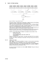
DiSEqC V1.1 control
LNB
->
DiSEqC
->
V1.1
switches the instrument to DiSEqC V1.1 control. V1.1 allows a total of up
to 256 SAT-IF layers to be controlled. V1.1 also incorporates DiSEqC component cascading. That
means that corresponding multi-switches or switching relays can be connected in series. This

