38
Chapter 6 - SAT Measuring Range
106 V3.2
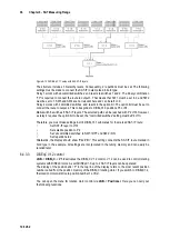
Figure 6-13 24 DiSEqC 1.1 setup with 64 SAT-IF layers
The structure includes 3 hierarchy levels. Consequently, 2 repetitions must be set. The following
settings must be made to connect the SAT-IF route marked in bold type:
Relay 1 works with ‘uncommitted switches’ and reacts to switches 1 and 2. The binary combination
“10” is required to connect the route to output 3. That means that SW1 must be set to 0 and SW2
must be set to 1. SW3 and SW4 are not relevant here and can be left on 0.
Relay 4 works with ‘committed switches’ and reacts to the option bit. The option bit must be set to
connect the route to output 2. This corresponds to DiSEqC1.0 positions P3 or P4.
Multi-switch 6 switches 8 SAT-IF layers. The selected path can be reached with P2 V/Hi. However,
as relay 4 requires the option bit to be set, the “committed switches” setting must be P4 V/Hi.
Therefore, you must make settings in all 4 DiSEqC1.1 submenus for the marked SAT-IF route:
•
Set SAT-IF layer to V/Hi
•
Set satellite position to P4
•
Set 'uncommitted switches’ to SW1:=OFF und SW2:=ON
•
Set repetitions to 2
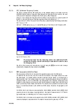
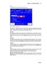
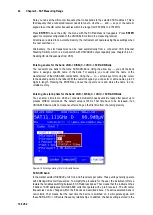
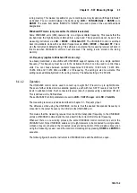
Afterwards, the display should show “P42/V/Hi”. This setting connects the SAT-IF route marked in
bold type in the example. All settings are incorporated in the tuning memory and can easily be
recalled later.
6.4.3.3
DiSEqC V1.2 control
LNB
->
DiSEqC
->
V1.2
activates the DiSEqC V1.2 control. V1.2 can be used to control rotating
systems with DiSEqC rotors. As with DiSEqC1.0, up to 4 SAT-IF layers can be operated.
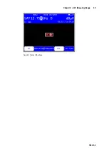
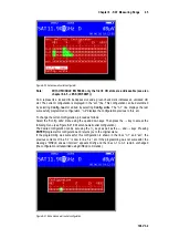
The display of the position after ‘P’ in the top line of the display refers to the most recent position
number called from the position memory of the DiSEqC rotating motor. If you switch to DiSEqC1.2,
the rotation motor will drive to position number 1 at first.
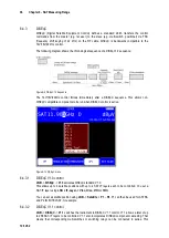
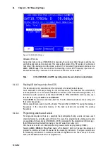
You can open the menu for rotation motor control via
LNB
->
Positioner
. Here you can carry out
the following functions:

