Chapter 7 - TV Measuring Range
73
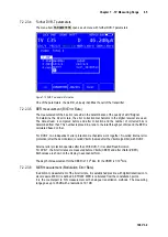
106 V3.2
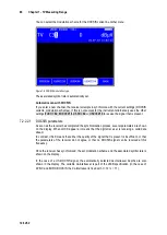
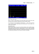
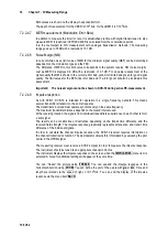
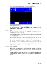
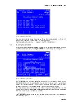
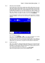
Figure 7-19 DVB-T2 Impulse response
The printed example shows an impulse response with a primary impulse (left picture edge) and
several secondary impulses at a distance of approximately 16 km from the primary impulse.
You can move the cursor (small triangle) left and right using the
←/→
keys. At the top right edge of
the picture, the transit time difference and attenuation in relation to the primary impulse is displayed
at the cursor position.
Peak-Search Function
While the impulse response is built up, the instrument determines the four highest secondary
impulses apart from the main impulse. If there are echoes, the cursor moves to the highest
secondary impulse after the second cycle. By pressing the keys ↑ and ↓ the cursor may be moved
to further echoes cyclically one after the other. The distance and/or the delay as compared to the
main impulse may be taking taken from the readings in the header of the diagram.
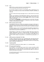
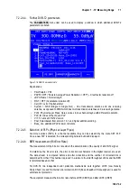
PE measurement (Packet Error)
7.2.2.4.10
Short interruptions in the DVB-T2 signal usually cannot be detected using MER and BER
measurement. They can make entire packets in the transport stream unusable for the MPEG
decoder, however. This can cause the picture to freeze temporarily or the sound to crackle.
The measuring receiver has a function with which corrupt transport stream packets are summed
from the point in time of entry of a new channel. This function runs in the background constantly.
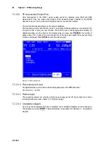
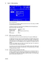
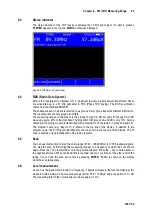
An additional window can be shown on the display using the menu item
PE-INFO
. The number of
packet errors (PE = Packet Error) and the amount of time that has passed since the last tuning
process is displayed.
Picture and sound check
7.2.2.4.11
For digital television, picture and sound decoding take place in the MPEG decoder (see Chapter 12
Remote supply
7.2.2.4.12
The measuring receiver can provide a remote power supply via the RF input socket for an active
receiving antenna (see also chapter 11.9 - Remote supply).
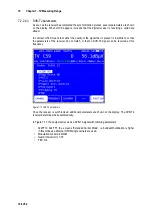
Constellation diagram
7.2.2.4.13
As soon as the measurement receiver is adjusted, the constellation diagram can be called up by
choosing the menu item
CONST
. Further information can be taken from Chapter 13 - Constellation


