76
Chapter 7 - TV Measuring Range
106 V3.2
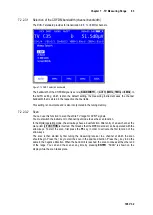
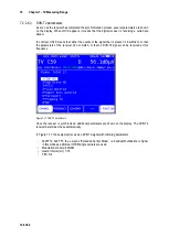
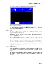
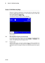
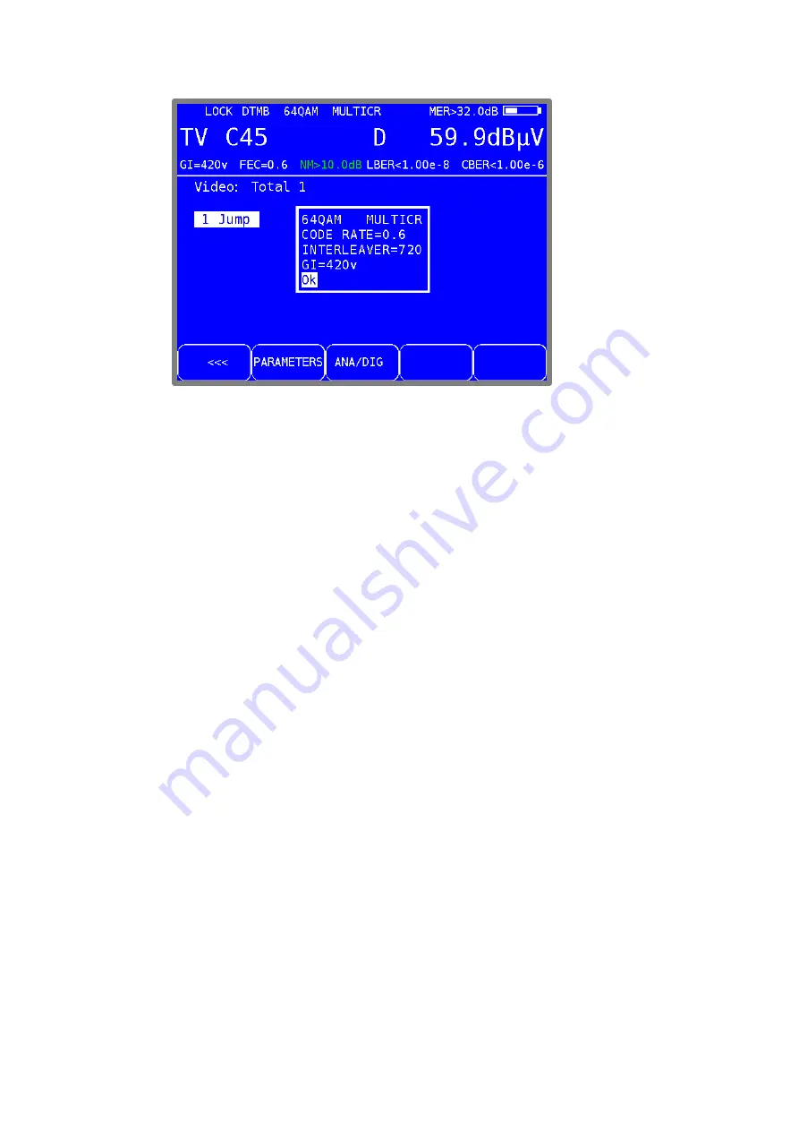
Figure 7-22 DTMB parameters
Once the receiver is synchronized, additional parameters are shown on the display. The DTMB
receiver determines these automatically.
In the figure shown above, the instrument receives a DTMB-Signal with the following parameters:
Multi carrier modulation: MULTICAR (C3780)
Multi carrier modulation
(MULTICAR – C3780)
Modulation scheme
64QAM
Guard-Interval(GI)
PN420 variable (equivalent 125 µs)
FEC
0.6
Time interleaver
M_720
BER measurement (Bit Error Rate)
7.2.2.5.3
The measurement of the bit error rate aids in the determination of the quality of a DTMB signal.
To determine the bit error rate, the error correction mechanisms in the digital receiver are used.
The data stream is compared before and after correction and the number of corrected bits is
determined from that. This number is placed in a ration to the total throughput of bits and the BER
is calculated based on that. With DTMB there are two independent error protections that work
together.
The inner error protection comes from LDPC (Low Density Parity Check), the external error
protection uses BCH (Bose Chaudhuri Hocguenghem).
The instrument measures the Bit Error Rate before LDPC (CBER) and after LDPC (LBER). Both
results will be shown on the display in exponential form. The measurement depth is for CBER
1•10
6
Bits and for LBER 1•10
8
Bits.
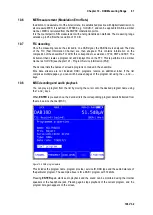
MER measurement (Modulation Error Rate)
7.2.2.5.4
In addition to measurement of the bit error rate, it is established practice with digital transmission to
also measure MER. It is defined in ETR290. MER is calculated from the constellation points. It is
the counterpart to S/N measurement with analogue transmission methods. The measuring range
goes up to 32 dB with a resolution of 0.1 dB.


