Chapter 8 - FM (VHF) Measuring Range
83
106 V3.2
8.3
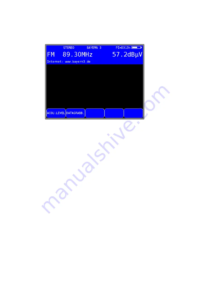
Stereo indicator
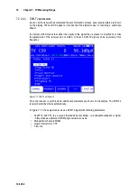
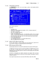
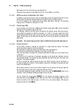
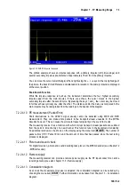
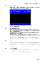
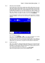
The stereo decoder of the VHF receiver evaluates the 19 kHz pilot signal. If a pilot is present,
STEREO
appears in the top line;
MONO
is otherwise displayed.
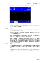
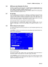
Figure 8-2 VHF stereo indicator display
8.4
RDS (Radio Data System)
RDS is the counterpart to videotext for TV. Additional to audio, digital data are transmitted. These
are modulated up to a 57 kHz subcarrier in PSK (Phase Shift Keying). The RDS specification
comes from the standard EN50067.
These data are sent in what are referred to as groups. Every group transmits different information.
The repetition rate of every group also differs.
The measuring receiver evaluates only the groups of type 0A, 0B, 2A and 2B. Groups 0A or 0B
make up approx. 40% of the total data. The proportion with groups 2A and 2B is only 15%. Among
other data, the program name is transmitted with a maximum of 8 characters in groups 0A and 0B.
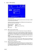
The program name (e.g. “Bayern 3") is shown in the top line of the display. In addition to the
program name, the PI (Program Identification) code is shown in the top line of the display. The PI
code is used as unique identification of the radio programs.
8.5
Scan
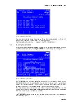
You can use this function to scan the entire range (87.40...108.20 MHz) for VHF broadcast signals.
You start the scan by first tuning the measuring receiver to a frequency at which the scan should
begin. Press the
↑
key to start the scan in the positive direction. Press the
↓
key to do the same in
the negative direction. When the band limit is reached, the scan continues at the other end of the
range. You can end the scan at any time by pressing
ENTER
. “SCAN” is shown on the display
while the scan takes place.
8.6
Level measurement
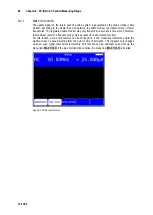
As soon as the instrument is tuned to a frequency, it begins to measure the level and displays the
measured value in dBµV. The measuring range is from 25 to 110 dBµV with a resolution of 0.1 dB.
The measuring rate for the numerical level value is approx. 3 Hz.


