Chapter 15 - Spectrum analyzer 111
106 V3.2
15.6
Switching between frequency and channel mode
You can only do this in the TV range. You can switch between modes via the menu items
CHANNEL
and
FREQUENCY
.
15.7
Level display
During each search, the level of the cursor frequency is measured and displayed in the upper right
edge of the screen in dBµV. Level measurement in analyzer mode is comparable to a pure
spectrum analyzer.
The power within the measuring bandwidth (RBW) is measured and converted into level in dBµV.
On the other hand, the level measurement in measuring receiver mode always measures the
power (level) in the channel.
TV range in the channel input mode:
The measuring instrument differentiates here automatically between analog and digital channels.
With analog channels, the level is based on the peak value of the video carrier. With digital
channels, the total power within the channel bandwidth is measured. It is not important here which
SPAN is set.
15.8
Progress bar
A yellow bar on the lower edge of the screen grows from left to right during each new search by the
analyzer. This allows you to follow the position of the “sweep”.
15.9
Level diagram in the broadband cable range
Assuming the measuring receiver is operating in the TV range, the mode is set to channel input
and the frequency segment is FULLSPAN respectively FULL EXT, the instrument provides a very
useful feature.
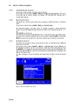
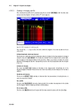
As you can see in Figure 15-3, the diagram shows the relationship of the levels in a broadband
cable system independent of the modulation (ATV or DVB-C) of the individual channels.
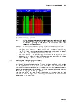
Figure 15-3 Level diagram
During the process, the instrument measures the levels of every individual channel and displays
them in the diagram as a green or red bar.


