Chapter 17 - Optical Receiver 125
106 V3.2
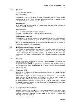
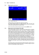
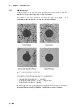
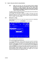
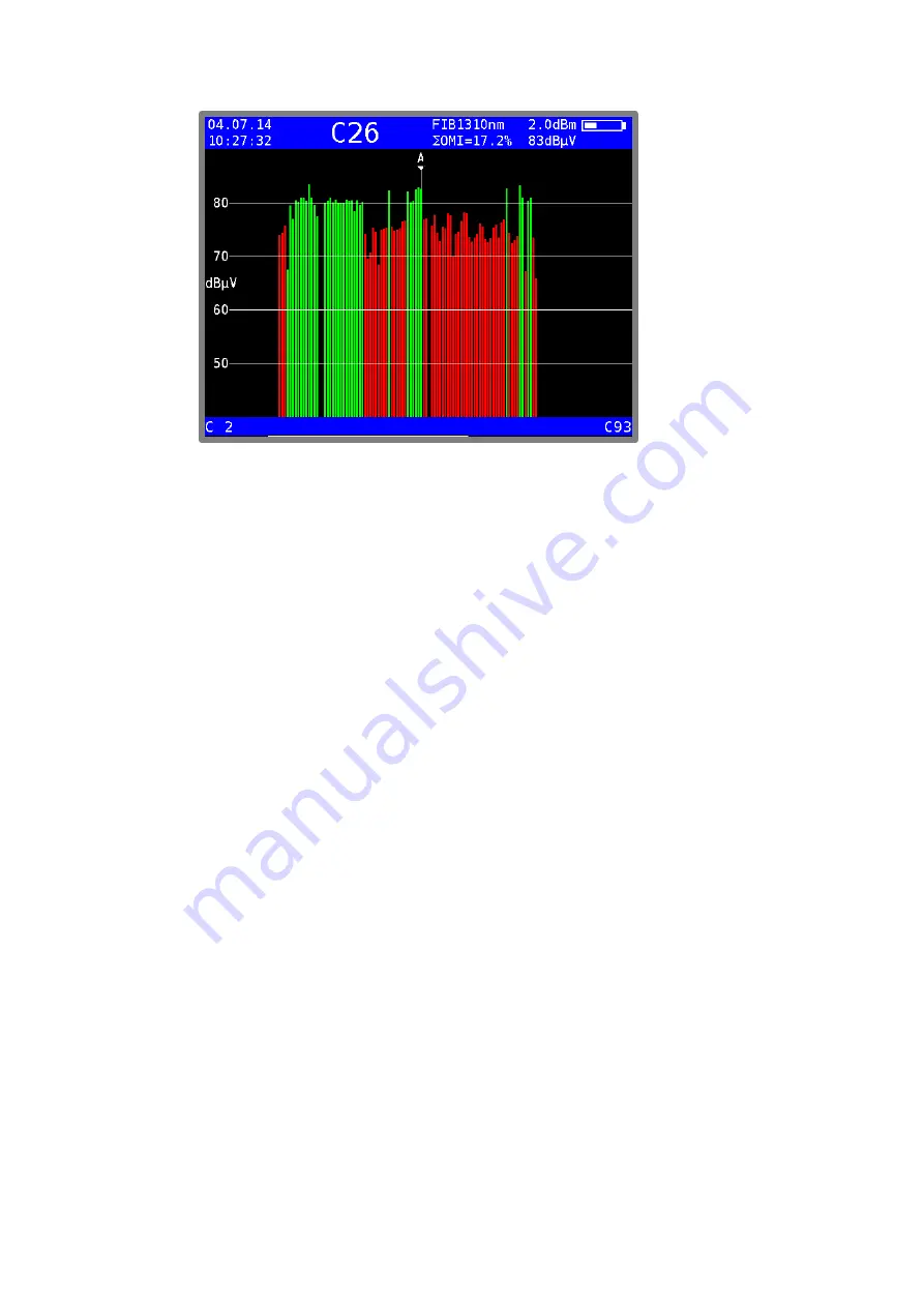
Figure 17-3 Spectrum analyzer in optical mode
Note!
The level specified after the OMI value corresponds to the internal RF level
after the optical/electrical converter. This information is only relative. This
specification is primarily used to determine the relationships between the
levels of the individual channels.
A brief overview of the relationships between optical power, RF level and OMI is provided below:
•
If the optical power is increased by 1 dB for optical transmission, the RF voltage increases by
2 dB after the optical receiver, while the optical modulation index (OMI) remains unchanged.
The RF voltage is proportional to the square of the optical power.
•
If the optical modulation index is doubled (e.g. increased from 2% to 4%) with the same
optical power, the RF voltage after the optical receiver increases by 6dB. This means that the
OMI and RF voltage are linearly proportional to one another.
17.6
Cleaning the fiber optic plug connection
The weak point of every optical transmission system lies in the splice and plug connections. For
plug connections, it is important to ensure that the contact surfaces are very clean. But the ferrules
of a fiber optic connection must also remain free of dust so that no contamination reaches the
connectors’ interfaces when they are plugged in. Industry-standard cleaning sets are available for
this purpose. Immediately after cleaning the plugs and connections, you should put dust covers on
them unless you are going to use them again right away.
The measuring receiver's fiber optic connection is equipped with a hinged lid that seals the
connection as soon as the plug is removed. However, you must still ensure that the area around
the lid remains free of contamination.

