background image

2

. FRAME COVERS/EXHAUST MUFFLER


2-2

                ATV 50

MX’ER 50

Summary of Contents for MX'ER 50

Page 1: ...By KWANG YANG Motor Co Ltd First Edition Jan 2006 All rights reserved Any reproduction or unauthorized use without the written permission of KWANG YANG Motor Co Ltd is expressly prohibited T100LB10DE...

Page 2: ...n The subsequent pages give detailed procedures for the section KWANG YANG MOTOR CO LTD OVERSEAS SALES DEPARTMENT OVERSEAS SERVICE SECTION TABLE OF CONTENTS GENERAL INFORMATION 1 FRAME COVERS EXHAUST...

Page 3: ..._________________________________________________________________________________ GENERAL INFORMATION __________________________________________________________________________________ SERIAL NUMBER 1...

Page 4: ...1 GENERAL INFORMATION 1 1 ATV 50 SERIAL NUMBER Location of Frame Serial Number Location of Engine Serial Number...

Page 5: ...cm2 1200 kPa 170 4 psi Open Port Intake Close Automatic controlled timing Open Exhaust Close Automatic controlled Intake Valve clearance Exhaust Idle speed rpm 1800 Lubrication type Separate type Oil...

Page 6: ...1200 kPa 170 4 psi Open Port Intake Close Automatic controlled timing Open Exhaust Close Automatic controlled Intake Valve clearance Exhaust Idle speed rpm 1800 Lubrication type Separate type Oil pum...

Page 7: ...omatic controlled timing Open Exhaust Close Automatic controlled Intake Valve clearance Exhaust Idle speed rpm 1800 Lubrication type Separate type Oil pump type Plunger type Oil filter type Full flow...

Page 8: ...ening bolts or nuts begin with larger diameter to smaller ones at several times and tighten to the specified torque diagonally Use genuine parts and lubricants When servicing the motorcycle be sure to...

Page 9: ...mutual working safety Disconnect the battery negative terminal before operation When using a spanner or other tools make sure not to damage the motorcycle surface After operation check all connecting...

Page 10: ...ified capacity After operation terminal caps shall be installed securely When taking out the connector the lock on the connector shall be released before operation Hold the connector body when connect...

Page 11: ...terminal cover or loose negative terminal Check the double connector cover for proper coverage and installation Insert the terminal completely Check the terminal cover for proper coverage Do not make...

Page 12: ...e sure that it is not interfering with any moving or sliding parts When fixing the wire harnesses do not make it contact the parts which will generate high heat Route wire harnesses to avoid sharp edg...

Page 13: ...tact a sharp edge or corner When rubber protecting cover is used to protect the wire harnesses it shall be installed securely Do not break the sheath of wire If a wire or harness is with a broken shea...

Page 14: ...with adjacent or surrounding parts in all steering positions When a testing device is used make sure to understand the operating methods thoroughly and operate according to the operating instructions...

Page 15: ...ollowing symbols represent the servicing methods and cautions included in this service manual Apply engine oil to the specified points Use designated engine oil for lubrication Apply grease for lubric...

Page 16: ...ead dia mm Torque kgf m N m lbf ft Remarks Cylinder head bolt Clutch drive plate nut Drive face nut Clutch outer nut A C G flywheel nut Oil check filler bolt MXU 50 MX ER 50 Oil drain plug Oil filler...

Page 17: ...A120E00001 Oil seal and bearing install A120E00014 Crankshaft install A120E00016 Universal holder A120E00017 Crankshaft crankcase install A120E00024 Crankcase puller A120E00026 Crankshaft Bearing pul...

Page 18: ...specified This will avoid abnormal noise and rise the durability of the motorcycle Steering knuckle Thrust Cover Bush Collar Steering Column Upper Rear Brake Cable Front Brake camshaft Oil Seal O ring...

Page 19: ...1 GENERAL INFORMATION 1 16 ATV 50 Sprocket hub Rear Axle Hub Collar Oil Seal Bearing Rear Brake Cam Axle Hub Collar Oil Seal Bearing Driven Sprocket Swing arm Thrust Cover...

Page 20: ...ATION 1 17 ATV 50 CABLE HARNESS ROUTING MX ER 50 Throttle Cable Rear Brake Cable Right Front Brake Cable Handlebar Switch Lead Front Brake Cable Left Front Brake Cable A C G Wire Starter Motor Wire Au...

Page 21: ...1 GENERAL INFORMATION 1 18 ATV 50 Throttle Cable Rear Brake Cable Ignition Coil Wire Fuel Tube Fuel Filter Oil Meter Wire Right Front Brake Cable Left Front Brake Cable...

Page 22: ...1 GENERAL INFORMATION 1 19 ATV 50 Wire Harness Rectifier Regulator Oil Tube Resistor Ignition Coil Right Front Brake Cable...

Page 23: ...1 GENERAL INFORMATION 1 20 ATV 50 Battery Starter Relay CDI Unit Fuse Rear Brake Cable Breather Hose Oil Meter Wire Positive Cable Negative Cable Main Switch...

Page 24: ...e Front Brake Cable Handlebar Switch Connectors Right Front Brake Cable Left Front Brake Cable Fuel Tank Breather Hose Left Headlight Turn Signal Light Connector Instrument Connector Horn Ignition Swi...

Page 25: ...FORMATION 1 22 ATV 50 Ignition Coil Air Cleaner Fuel Valve Inlet Hose Oil Inlet Hose Auto Choke Connector Starter Motor Connector Spark Plug Cap Throttle Cables Neutral Switch Wire MXU 50 REVERSE Rear...

Page 26: ...oil Cable Ignition Coil Fuel Drain Hose Hazard Unit Headlight Control Unit Ignition Coil Wire Throttle Cable Starter Motor Cable ACG Wire Fuel Unit Connectors Transmission Case Breather Hose MXU 50 RE...

Page 27: ...Regulator CDI Starter Motor Speedometer wire Harness Wire ACG Connector ACG Connector Oil Level Connectors Fuel Unit Connectors Rectifier Regulator Connector Pulser Connector Carburetor Drain Hose Tra...

Page 28: ...N 1 25 ATV 50 Fuse Box Start Relay Tail Light Brake light Wire Negative Cable Rear Left Turn Signal Light Rear Right Turn Signal Light Connectors Positive Cable Harness Wire Speed Sensor Speedometer W...

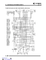
Page 29: ...1 GENERAL INFORMATION 1 26 ATV 50 WIRING DIAGRAM MX ER 50 ON ROAD...

Page 30: ...1 GENERAL INFORMATION 1 27 ATV 50 WIRING DIAGRAM MX ER 50 OFF ROAD...

Page 31: ...1 GENERAL INFORMATION 1 28 ATV 50 WIRING DIAGRAM MXU 50 ON ROAD...

Page 32: ...1 GENERAL INFORMATION 1 29 ATV 50 WIRING DIAGRAM MXU 50 REVERSE ON ROAD...

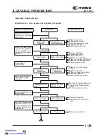
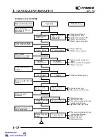
Page 33: ...e eIncorrect ignition timing cFlooded carburetor dThrottle valve excessively open cFaulty auto bystarter Check if fuel reaches carburetor by loosening drain screw Remove spark plug and install it into...

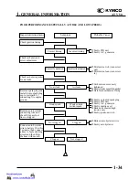
Page 34: ...too rich turn screw out dMixture too lean turn screw in Check if fuel reaches carburetor by loosening drain screw Inspection Adjustment Symptom Probable Cause Fuel reaches carburetor Good spark Remov...

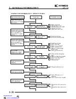
Page 35: ...arter cFaulty auto bystarter Inspection Adjustment Symptom Probable Cause No air leak Not clogged Clogged Air leaks Clogged Not Clogged Check carburetor gasket for air leaks Connect auto bystarter wir...

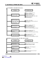
Page 36: ...d up in combustion chamber dPoor quality fuel eClutch slipping fMixture too lean Inspection Adjustment Symptom Probable Cause Engine speed increases Engine overheats Correct timing Engine does not kno...

Page 37: ...re dFaulty auto bystarter Inspection Adjustment Symptom Probable Cause Clogged Not clogged Remove spark plug and install it into spark plug cap to test spark by connecting it to engine ground Check ig...

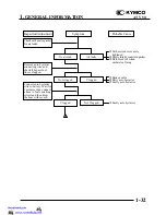
Page 38: ...Inspection Adjustment Symptom Probable Cause Clogged Not clogged Check ignition timing Connect auto bystarter wire to battery Wait for 5 minutes then connect a hose to fuel enriching circuit and then...

Page 39: ...drive belt dWorn drive belt eWeak driven face spring fWorn or seized driven pulley bearings STEERING HANDLEBAR DOES NOT TRACK STRAIGHT Front and rear tire pressures are normal cSteering stem nut too...

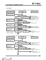
Page 40: ...cam fWorn brake drum cWorn brake linings dForeign matter on brake linings eRough brake drum contacting area cSluggish or elongated brake cables dBrake shoes improperly contact brake drum eWater and mu...

Page 41: ...onnected wire cFaulty float dBroken or shorted wire in meter cDamaged oil tank dForeign matters in oil tank Inspection Adjustment Symptom Inspection Adjustment Probable Cause Symptom Probable Cause Si...

Page 42: ...Adjustment Symptom Symptom Signals operate properly Signals operate properly Signals dim remain on or don t operate Signals dim remain on or don t operate Pointer does not move Pointer does not move...

Page 43: ...uck closed Inspection Adjustment Inspection Adjustment Inspection Adjustment Symptom Symptom Symptom Signals operate properly Signals operate properly Signals dim remain on or don t operate Signals di...

Page 44: ...________________________________________________________________ __________________________________________________________________________________ FRAME COVERS EXHAUST MUFFLER _______________________...

Page 45: ...damaged Make sure to route cables and harnesses according to the Cable Harness Routing TORQUE VALUES Exhaust muffler lock bolt 3 3 kgf m 33 N m 24 lbf ft Exhaust muffler joint lock nut 1 2 kgf m 12 N...

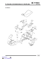
Page 46: ...2 FRAME COVERS EXHAUST MUFFLER 2 2 ATV 50 MX ER 50...

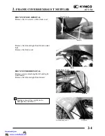
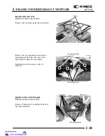
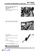
Page 47: ...e seven screws and two bolts attaching the left rear fender Remove seven screws and two bolts attaching the right rear fender Remove the left rear fender under bolt Remove the left rear fender Remove...

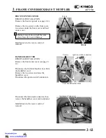
Page 48: ...the left and right front fender under bolt Remove the front cover FRONT FENDER REMOVAL Remove screws attaching the left and right front fender Remove the left and right front fender Bolts Screws Front...

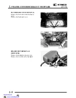
Page 49: ...5 ATV 50 FLOOR BOARD COVER REMOVAL Remove the four bolts on the floorboard cover Remove the floorboard cover HEADLIGHT REMOVAL MX ER 50 Remove the headlight connector wire Remove the two bolts on the...

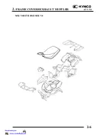
Page 50: ...2 FRAME COVERS EXHAUST MUFFLER 2 6 ATV 50 MXU 50 REVERSE MXU 50...

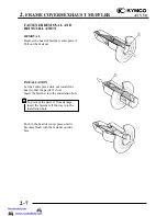
Page 51: ...ull out the fastener INSTALLATION Let the center piece stick out toward the head so that the pawls close Insert the fastener into the installation hole Push in the head of center piece until it become...

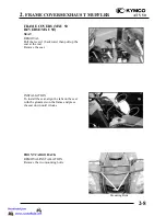
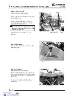
Page 52: ...Pull the lever 1 backward then pull up the seat at the rear Remove the seat INSTALLATION To install the seat align the tabs on the seat with the grommets on the frame and press the seat down until it...

Page 53: ...val FRONT CARRIER REMOVAL INSTALLATION Remove front cargo rack see page 2 8 Disconnect the right and left signal light connectors ON ROAD Remove the bolts from the right left headlight case Remove the...

Page 54: ...the two mounting bolts and two mounting nuts from the rear cargo rack right left side under the rear fender Installation is in the reverse order of removal RIGHT LEFT FOOTBOARD REMOVAL INSTALLATION R...

Page 55: ...ee page 2 8 Remove the right left footboard see page 2 10 Remove the two bolts fastener and right side cover Remove the two bolts fastener and left side cover Installation is in the reverse order of r...

Page 56: ...ON Remove the front center cover see page 2 12 Disconnect the fuel tank breather hose from the handlebar cover Remove the two screws and raise the handlebar cover Disconnect the ignition switch connec...

Page 57: ...emoval MXU 50 REVERSE Remove the bolt and then remove the drive select lever grip FRONT FENDER REMOVAL INSTALLATION Remove front carrier see page 2 9 front center cover see page 2 12 fuel tank cover s...

Page 58: ...ight left footboard see page 2 10 Remove one bolt and one nut then remove the oil tank Remove the three bolts from the rear fender Raise the rear fender and pass the fuse battery cables start relay th...

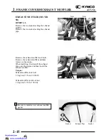
Page 59: ...uffler lock bolts Remove the exhaust muffler and them remove exhaust pipe When installing first install the exhaust pipe onto the engine and then install the exhaust muffler Torque Exhaust muffler loc...

Page 60: ...wo bolts attaching the exhaust muffler then remove the exhaust muffler Inspect the gasket If the exhaust gas leaks the gasket should be replaced Install by reversing the removal sequence Torque Exhaus...

Page 61: ...________________________________________________ INSPECTION ADJUSTMENT __________________________________________________________________________________ SERVICE INFORMATION 3 1 MAINTENANCE SCHEDULE 3...

Page 62: ...tandard NGK BR8HAS Idle speed 1800 100rpm Gear oil capacity MXU 50 MX ER 50 At disassembly 0 12 liter 0 11 lmp qt 0 13 Us qt At change 0 09 liter 0 08 lmp qt 0 1 Us qt Gear oil capacity MXU 50 REVERSE...

Page 63: ...ive maintenance procedures if followed will ensure more reliable vehicle operation and a longer service life The need for costly overhaul work will be greatly reduced This information applies to vehic...

Page 64: ...Minor adjustment is made with the adjusting nut at the throttle to swing above Slide the rubber cover out and adjust by loosening the lock nut and turning the adjusting nut AIR CLEANER AIR CLEANER REP...

Page 65: ...l Squeeze out the excess oil CHANGE INTERVAL More frequent replacement is required when riding in unusually dusty or rainy areas Use parts cleaning solvent only Never use gasoline or low flash point s...

Page 66: ...BR8HAS Measure the spark plug gap Spark Plug Gap 0 6 0 7 mm 0 024 0 028 LUBRICATION SYSTEM Oil Filter Cleaning Disconnect the oil tube at the oil pump side and allow oil to drain into a clean contain...

Page 67: ...by loosening the control cable lock nut and turning the adjusting nut After adjustment tighten the lock nut If the oil pump is not synchronized properly the following will occur Excessive white smoke...

Page 68: ...fan Warm up the engine and check the ignition timing with a timing light When the engine is running at the specified rpm the ignition timing is correct if the F mark on the flywheel aligns with the i...

Page 69: ...king cylinder head gasket Worn piston rings Worn piston cylinder If the compression is high it indicates that carbon deposits have accumulated on the combustion chamber and the piston head FINAL REDUC...

Page 70: ...MX ER 50 At disassembly 0 12 liter 0 11 lmp qt 0 13 Us qt At change 0 09 liter 0 08 lmp qt 0 1 Us qt MXU 50 REVERSE At disassembly 0 3 liter 0 26 lmp qt 0 32 Us qt At change 0 25 liter 0 22 lmp qt 0...

Page 71: ...imit 16 5mm 0 7 in Replace the drive belt if out of specification BRAKE SHOE Replace the brake shoes if the arrow on the wear indicator plate aligns with the punch mark on the brake panel when the bra...

Page 72: ...ters out that the free play is decreased The difference between both clearances should be 2 mm 0 08 in or less when front brake is applied Tighten the lock nuts REAR BRAKE drum brake Measure the rear...

Page 73: ...ine Turn on the headlight switch Adjust the headlight aim by turning the headlight aim adjusting screw MXU 50 REVERSE MXU 50 Turn the ignition switch ON and start the engine Turn on the headlight swit...

Page 74: ...ssive play Check the tie rod ends Turn the handlebar to the left and or right until it stops completely then slightly move the handlebar from left to right Replace the tie rod ends if tie rod end has...

Page 75: ...e in step Mark both tie rods ends This reference point will be needed during adjustment Loosen the lock nuts tie rod end of both tie rods The same number of turns should be given to both tie rods righ...

Page 76: ...Rear 22 10 8 Check the front axle nut for looseness Check the rear axle nut for looseness If the axle nuts are loose tighten them to the specified torque Torque Front 7 kgf m 70 N m 50 lbf ft Rear 7 k...

Page 77: ...vel place Check drive chain slack Adjust if out of specification Drive chain slack 10 20 mm 0 4 0 8 in Adjust drive chain slack Elevate the rear wheels by placing a suitable stand under the rear of fr...

Page 78: ...obtained Turn in Slack is increased Turn out Slack is decreased Tighten four bolts attaching rear axle hub to the specification While pushing up or down on the chain to zero slack Torque 7 kgf m 70 N...

Page 79: ...ing parts of each lever FRONT REAR SUSPENSION LUBRICATION Inject grease into the nipples using a grease gun until slight over flow is observed from the thrust covers Nipple Damaged cable sheath may ca...

Page 80: ..._______________________________ __________________________________________________________________________________ __________________________________________________________________________________ LU...

Page 81: ...4 LUBRICATION SYSTEM 4 1 ATV 50 LUBRICATION SYSTEM...

Page 82: ...TIONS Recommended Motor Oil SAE20W20 2 stroke Motor Oil Oil Capacity 1 liter 0 88 lmp qt 1 06 Us qt Light comes on 0 25 liter 0 22 lmp qt 0 27 Us qt TROUBLESHOOTING Excessive white smoke or carbon dep...

Page 83: ...Damage to crankcase mating surface Damage to pump body Control lever operation Oil leaks through oil seals Worn or damaged pump pinion Do not allow foreign matters to enter the crankcase Before removi...

Page 84: ...Connect the oil inlet line and oil outlet line properly Connect the oil pump control cable Bleed air from the oil pump Lubricate the O ring with grease or engine oil before installation Make sure that...

Page 85: ...orce air out of the tube by filling it with oil 2 Start the engine and allow it to idle with the oil control lever in the fully open position Visually check the oil flow 3 If there is no oil flowing o...

Page 86: ...rom the oil tank see page 2 14 Disconnect the oil inlet line Drain the oil inside the oil tank into a clean container Remove the oil tank The installation sequence is the reverse of removal Connect th...

Page 87: ...__________________________________________________ __________________________________________________________________________________ FUEL SYSTEM ______________________________________________________...

Page 88: ...5 FUEL SYSTEM 5 1 ATV 50...

Page 89: ...dle speed 1800 100 rpm Throttle grip free play 1 4 mm 0 04 0 16 in SPECIAL TOOL Float level gauge TROUBLESHOOTING Engine does not start Lean mixture No fuel in tank Clogged fuel jets Faulty float valv...

Page 90: ...RBURETOR REMOVAL Loosen the carburetor cap and remove the throttle valve Disconnect the throttle cable from the throttle valve Remove the throttle valve spring carburetor cap and rubber seal Carbureto...

Page 91: ...he jet needle on the throttle valve and secure with the needle clip Install the rubber seal on the throttle cable and then install the carburetor cap and throttle valve spring Connect the throttle cab...

Page 92: ...owing adjustments and inspections Throttle cable free play 3 3 Idle speed adjustment 3 7 CARBURETOR REMOVAL Remove the air cleaner by removing the air cleaner band screw and attaching bolts Disconnect...

Page 93: ...tarter wire terminals Resistance 5 10 minutes minimum after stopping the engine If the resistance exceeds 5 replace the auto bystarter with a new one After the engine stops for 30 minutes connect a ho...

Page 94: ...blow the hose with mouth If air can be blown into the hose the auto bystarter is faulty and replace it with a new one AUTO BYSTARTER REMOVAL Remove the auto bystarter cover Remove the two auto bystar...

Page 95: ...dy until it bottoms Install the set plate and then tighten the two screws FLOAT FLOAT VALVE JETS FLOAT CHAMBER Remove the two float chamber screws and the float chamber Remove the screw and O ring Rem...

Page 96: ...ing the throttle stop screw or air screw record the number of rotations until it seats lightly Then remove them Remove the main jet and needle jet holder CARBURETOR PASSAGES CLEANING Blow compressed a...

Page 97: ...NSPECTION Slightly tilt the carburetor and measure the float level with the float valve just connecting the float arm Float Level 8 6 mm 0 34 in Replace the float if the level is out of the specified...

Page 98: ...ten the two lock nuts Connect the fuel tube and auto bystarter wire connector Install the carburetor cap 5 3 Install the fuel tube Install the air cleaner onto the carburetor and tighten the band scre...

Page 99: ...the throttle stop screw to obtain the specified idle speed Idle Speed 1800 100 rpm Air Screw Opening 2 1 2 turns Slightly increase the engine speed and make sure that the engine does not miss or run e...

Page 100: ...nd reed Replace the valve if necessary INSTALLATION Install the reed valve in the reverse order of removal Bolts Reeds Intake Manifold Reed Valve Seat Reed Stopper Do not disassemble or bend the reed...

Page 101: ...front fender Remove two bolts and two nuts on the end of the fuel tank Switch the fuel valve OFF Disconnect the fuel tubes Remove the fuel tank and fuel valve Bolts Fuel Tank Screws Seat Lever Center...

Page 102: ...uel valve strainer for dirt and clog Clean if necessary Replace the O rings with new ones if they are damaged or deteriorated AIR CLEANER REMOVAL Remove the five screws on the air cleaner case cover a...

Page 103: ...________________________________________________________________________ __________________________________________________________________________________ ____________________________________________...

Page 104: ...k or other adjustable support is required to support and maneuver the engine Be careful not to damage the machine body cables and wires during engine removal Use shop towels to protect the motorcycle...

Page 105: ...ching the air cleaner case Loosen the band between the air cleaner and carburetor to remove the air cleaner case Remove the carburetor cap Disconnect the auto bystarter A C generator pulser and starte...

Page 106: ...d outlet line from the oil pump Remove the two carburetor lock nuts Remove the carburetor Oil Inlet Line Control Cable Spark Plug Cap Carburetor Lock Nuts Starter Motor Wire Connector Auto Bystarter W...

Page 107: ...remove the drive select rod from drive select arm MXU 50 REVERSE Remove the three bolts at the drive sprocket cover then remove the protector cover Remove the rear drive chain gear on the bolts Remov...

Page 108: ...t Remove the front left engine bracket bolt nut Remove the rear left engine bracket bolt nut Remove the engine to the right side of the frame ENGINE INSTALLATION Install the engine and tighten the eng...

Page 109: ..._________________________________________________________________ __________________________________________________________________________________ ___________________________________________________...

Page 110: ...7 CYLINDER HEAD CYLINDER PISTON 7 1 ATV 50...

Page 111: ...2 03 0 4812 Piston pin O D 11 994 0 47976 12 0 48 11 98 0 4792 Piston to piston pin clearance 0 002 0 00008 0 014 0 00056 0 03 0 0012 Piston ring end gap top second 0 1 0 004 0 25 0 01 0 4 0 016 Conne...

Page 112: ...remove the fan cover Remove the bolt attaching the engine hood to remove the engine hood The installation sequence is the reverse of removal Remove the spark plug Remove the cylinder head bolts and t...

Page 113: ...e with a straight edge and feeler gauge Service Limit 0 1 mm 0 004 in replace if over CYLINDER HEAD INSTALLATION Install the cylinder head on the cylinder properly Install a new cylinder head gasket o...

Page 114: ...ft Install the spark plug Torque 1 4 kgf m 14 N m 10 1 lbf ft Engine Hood Installation Install the engine hood 7 3 Install the spark plug cap 7 3 Install the exhaust muffler 12 15 or 12 16 Perform th...

Page 115: ...on pin and piston Spread each piston ring and remove by lifting it up at a point just opposite the gap Remove the expander Piston Pin Clip Piston Piston Pin Cylinder Do not damage or scratch the pisto...

Page 116: ...easure the cylinder bore at three levels of A B and C in both X and Y directions Avoid the port area Take the maximum figure measured to determine the cylinder bore Service Limit 39 05 mm 1 56 in repl...

Page 117: ...t 0 1 mm 0 004 in replace if over Measure the piston pin hole I D Service Limit 12 03 mm 0 481 in replace if over Measure the piston pin O D Service Limit 11 98 mm 0 479 in replace if below Measure th...

Page 118: ...CYLINDER INSTALLATION First install the expander in the second ring groove Then install the top and second rings in their respective ring grooves The piston rings should be pressed into the grooves w...

Page 119: ...the ring end gaps are aligned with the piston ring pins in the ring grooves Lubricate the cylinder inside and piston rings with engine oil and install the piston into the cylinder while compressing th...

Page 120: ..._________________________________________________________________ __________________________________________________________________________________ ___________________________________________________...

Page 121: ...8 A C GENERATOR 8 1 ATV 50...

Page 122: ...IONS All A C generator maintenance and inspection can be made with the engine installed Refer to Section 15 16 for A C generator inspection TORQUE VALUE Flywheel nut 3 8 kgf m 38 N m 27 4 lbf ft SPECI...

Reviews: