2
. FRAME COVERS/EXHAUST MUFFLER
2-12
ATV 50
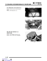
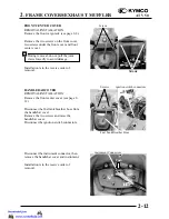
FRONT CENTER COVER
REMOVAL/INSTALLATION
Remove the front cargo rack (see page 2-8).
Remove the two screws on the front cover,
two screws under the front cover and front
center cover.
Installation is in the reverse order of
removal.
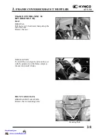
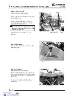
HANDLEBAR COVER
REMOVAL/INSTALLATION
Remove the front center cover (see page 2-
12).
Disconnect the fuel tank breather hose from
the handlebar cover.
Remove the two screws and raise the
handlebar cover.
Disconnect the ignition switch connectors.
Disconnect the instrument connector, then
remove the handlebar cover and instrument.
Installation is in the reserve order of
removal.
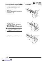
During removal, do not pull the joint
claws forcedly to avoid damage.
*
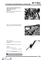
Screws
Screws
Screws ignition switch connectors
instrument Connectors
Fuel Tank Breather Hose
Push
Summary of Contents for MX'ER 50
Page 29: ...1 GENERAL INFORMATION 1 26 ATV 50 WIRING DIAGRAM MX ER 50 ON ROAD...
Page 30: ...1 GENERAL INFORMATION 1 27 ATV 50 WIRING DIAGRAM MX ER 50 OFF ROAD...
Page 31: ...1 GENERAL INFORMATION 1 28 ATV 50 WIRING DIAGRAM MXU 50 ON ROAD...
Page 32: ...1 GENERAL INFORMATION 1 29 ATV 50 WIRING DIAGRAM MXU 50 REVERSE ON ROAD...
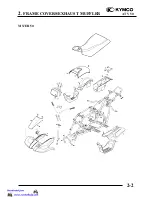
Page 46: ...2 FRAME COVERS EXHAUST MUFFLER 2 2 ATV 50 MX ER 50...
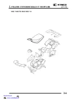
Page 50: ...2 FRAME COVERS EXHAUST MUFFLER 2 6 ATV 50 MXU 50 REVERSE MXU 50...
Page 81: ...4 LUBRICATION SYSTEM 4 1 ATV 50 LUBRICATION SYSTEM...
Page 88: ...5 FUEL SYSTEM 5 1 ATV 50...
Page 110: ...7 CYLINDER HEAD CYLINDER PISTON 7 1 ATV 50...
Page 121: ...8 A C GENERATOR 8 1 ATV 50...

