6-11
6
CD110
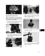
8. Install the proper shim onto the ring gear spider
assembly making sure the chamfer side of the
shim is facing toward the ring gear. Install the ring
gear in the housing; then install the outside shim
with the chamfer side of the shim toward the ring
gear.
NOTE: The spider and ring gear assembly must
be replaced as a complete unit.
CC896
CC897
9. Install left bearing flange/bearing assembly and
seat it firmly into the cover.
CF267A
10. Apply a liberal amount of grease to the O-ring;
then install it on the assembled cover assembly
making sure to seat the O-ring down around the
circumference of the bearing flange.
11. Making sure the O-ring is properly positioned on
the gear case cover assembly, install the cover
with existing hardware. Account for the ID tag.
Tighten the cap screws to 23 ft-lb.
NOTE: Grease can be applied to the O-ring for
ease of assembling.
NOTE: If a new gear case housing is being
installed, tighten the cap screws to 25-31 ft-lb.
Removing Needle Bearing
NOTE: Removing the needle bearing is rarely
necessary. Avoid removing the needle bearing
unless the bearing is clearly damaged.
NOTE: This procedure can be performed on a
rear gear case.
1. Place a 1/4 in. drill bit on the inside surface of the
needle bearing (against the bottom side); then drill
through the pinion shaft needle bearing housing.
CC885
2. Using a propane torch, heat the area surrounding
the needle bearing to soften the Loctite.
Summary of Contents for MXU 450i
Page 17: ...Oil level stick...
Page 23: ...Low range High range Neutral Reverse...
Page 25: ...1 mm 0 039 in...
Page 126: ...A B...
Page 127: ...LCD Gauge Connector LCD Gauge Connector...
Page 134: ...9 4 NOTES...
Page 135: ......


