background image

11

. EFI SYSTEM                                                             

MXU 450i


11-7

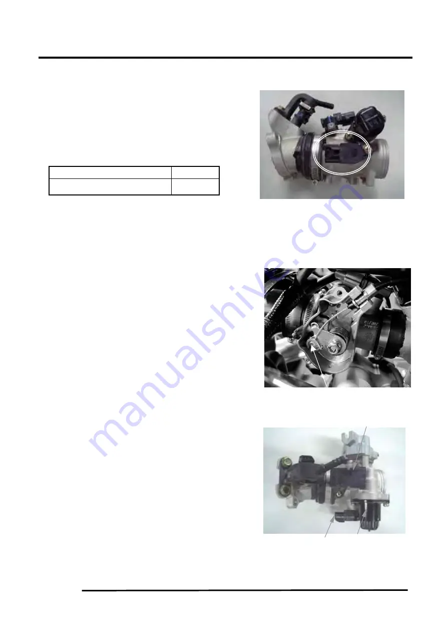
TPS INSPECTION

Support the ATV on a level surface.
Turn the ignition switch to “ON”.
Measure if the ECU voltage outputs to TPS
between the following terminals of the TPS
connector.

Terminal

Normal

V/R (+) -V/G(-)

5 V

Throttle position sensor (TPS) resistance
3500~6500

Ω

(at 20°C/68°F)

REMOVAL

Disconnect the throttle cable ends from
throttle seat.

Disconnect the TPS, ISC and T- MAP sensor
connectors.
Loosen the air cleaner connecting hose band
screw.
Loosen the intake manifold band screw.
Remove the throttle body, T-MAP sensor,
TPS sensor and ISC sensor as a set.

                                  Cable Ends

                                          T-MAP Sensor

     TPS Sensor   ISC

Summary of Contents for MXU 450i

Page 1: ...on Note and At This Point to emphasize imoortant information The symbol i Hilii J Identifies personal safety related Information Be sure to follow the directive because it deals With the possibility o...

Page 2: ...TENTS General Specifications 1 2 Torque Specifications 1 2 Tightening Torque Frame parts 1 3 Tightening Torque Engine parts 1 4 Break In Procedure 1 5 Gasoline Oil Lubricant 1 5 Genuine Parts 1 5 Prep...

Page 3: ...heelbase 121 7cm 48 m Tire Stze Front 24 8 12 Ttre Stze Rear 24 10 12 Tire InflatiOn Pressure 0 29 kg cm2 4 psi MISCELLANEOUS Dry WetQht Approx 277 5kg 6111b Gas Tank Capactty Rated 15L 375US Gal Orff...

Page 4: ...5 6 41 56 4 8 35 95801 10035 06 5 BRAKE FRONT BRAKE DISC AND FRONT HUB M6XI O 1 7 2 5 17 25 2 15 90106 PW B1 9000 REAR BRAKE DISC AND REAR HUB M6XI O 1 7 2 5 17 25 2 15 90106 PI Bl 9000 FRONT REAR CAL...

Page 5: ...R SPECIAL SCREW 33 4 5 3 4 5 33 4 THREAD LOCK 90020 PWB I 9000 ARM M 14x I 5 8 CAM CHAIN SPECIAL BOLT 14 16 I 4 I 6 15 14531 PWB I 9000 TENSIONER PIVOT M8xl 25 9 ACG ONE WAY BOLT SOCKET 17 7 21 6 I 8...

Page 6: ...enance after break in should include checking of all pre scribed adjustments and tightening of all fasteners Gasoline Oil Lubricant RECOMMENDED GASOLINE The recommended gasoline to use is 87 minimurn...

Page 7: ...ughly DO NOT get water into any part of the engine or air intake 3 Either drain the gas tank or add Fuel Stabilizer to the gas in the gas tank Remove the air filter housing cover and air filter Start...

Page 8: ...system CAUTION Connect the positive battery cable first then the negative 6 Check the entire brake systems fluid level pads etc all controls lights and headlight aim adjust or replace as necessary Ti...

Page 9: ...Compression 2 7 Spark Plug 2 8 Muffler Spark Arrester 2 8 Adjusting Throttle Cable 2 9 Engine Transmission Oil Filter Strainer 2 9 Front Differential Rear Drive Lubricant 2 11 Tires 2 12 Steering Com...

Page 10: ...ner I I Front Differential Rear Drive Lubricant I I Tires Air Pressure I I Steering Components I I I V Belt I I Suspension Ball joint boots drive I I axle boots front and rear tie rods differential an...

Page 11: ...g lead acid batteries Always read and follow instructions provided with battery chargers and battery products WARNING Anytime service is performed on a battery the fol lowing must be observed keep spa...

Page 12: ...er and test the battery volt age The meter should read 12 5 or more DC Volts lfthe voltage is as specified the battery is ready for service NOTE If voltage in step 9 is below specifications charge the...

Page 13: ...arefully examine the element for tears before and after cleaning it Replace the element with a new one if it is torn 6 Clean any dirt or debris from inside the air cleaner Be sure no dirt enters the c...

Page 14: ...ce Ifclearance is not w1thm specrfica tons loosen the jam nut and r tate th tappe t adj 1ster screw lmtil the clearance IS w1thm specrfic tJons Tighten each jam nut securely after completJng the adjus...

Page 15: ...dle 8 Placethe two tappet covers with 0 rings into posi tion then tighten the covers securely 9 lnstall the spark plug then install the timing inspection plug Testing Engine Compression To test engine...

Page 16: ...ug be sure to tighten it securely A new spark plug should be tightened 1 2 tum once the washer contacts tJ1e cylinder head A used spark plug shouJd be tightened 1i8 1 4 tum once the washer contacts th...

Page 17: ...Oil level stick...

Page 18: ...nd wipe it with a clean cloth 12 Install the oil level into engine case NOTE The oil level stick should be threaded into the case for checking purposes 13 Remove the oil level stick the engine oil lev...

Page 19: ...d 80W 90 hypoid gear lubricant as necessary To change the lubricant use the following procedure 1 Place the ATV on level ground 2 Remove each oil fill plug KC0077A 3 Drain the oil into a drain pan by...

Page 20: ...cracked F Knuckles not worn cracked or damaged G Cotter pins not damaged or missing Driveshaft Coupling The following drive system components should be inspected periodically to ensure proper operatio...

Page 21: ...wing proce dure l Remove the protcc6vc rubber boot from the rear of the headlight housing then remove the iring harness connector from the back of the headlight bulb 2 Press in and release the spring...

Page 22: ...ting bolt in direction a To a headlight beam turn the adjusting bolt in direction b To a headlight beam turn the adjusting bolt in direction c To a headlight beam turn the adjusting bolt in direction...

Page 23: ...Low range High range Neutral Reverse...

Page 24: ...uid in the reservoir will result in air in the sys tem D Repeat step C until U1e brake lever js finn E At tllis poinL perfom1 step B C and D on the od1 er PRONT bleeder screw dlen move to the REAR ble...

Page 25: ...1 mm 0 039 in...

Page 26: ...e driven pulley fixed face and push the movable face open allowing the V belt to drop down between the pulley faces approximately 3 4 in KC137 5 Pinching the V belt together in front of the driven pul...

Page 27: ...rotruding through the movable drive face install the nut and tighten to 147 ft lb KC152A KC141 4 Remove the cap screw from the fixed driven face then rotate the pulleys counterclockwise until the driv...

Page 28: ...2 20 6 Slide the auxilial brake pedal fully onto the pivot stud engaging the master cylinder then secure with the flat washer and cap screw and tighten to 20ft lb...

Page 29: ...SECTION 3 ENGINE TRANSMISSION TABLE OF CONTENTS Engine Transmission 3 2 Specifications 3 3 Troubleshooting 3 4 Table of Contents 3 7 3 1...

Page 30: ...frame NOTE KYMCO recommends the use of new gaskets lock nuts and seals and lubricating all internal components when servicing the engine transmission NOTE Some photographs and illustrations used in t...

Page 31: ...alve Face Seat Width min intake 2 25 mm 0 089 in exhaust 2 55 mm 0 1 00 in 2nd 1 17 1 19 mm 0 0468 0 0476 in Valve Seat Angle intake exhaust 45 Piston Pin Bore max 20 008 mm 0 7877 Valve Face Radial R...

Page 32: ...1 Gas tank vent hose obstructed 1 Clean vent hose 2 Throttle body obstructed 2 Clean Throttle body 3 Fuel hose obstructed 3 Clean replace hose 4 Fuel filter obstructed 4 Clean replace fuel filter 5 F...

Page 33: ...ondition 1 Drive driven bevel gears damaged worn 2 Backlash excessive 3 Tooth contact improper 4 Bearing damaged 5 Gears worn rubbing 6 Splines worn 7 Final driven shaft thrust clearance too large Pro...

Page 34: ...Engine overheats Condition 1 Carbon deposit piston crown excessive 2 Oil low 3 Octane low gasoline poor 4 Oil pump defective 5 Oil circuit obstructed 6 Engine Coolant too low 7 Intake manifold leakin...

Page 35: ...ure sensor connector Remove the water hose to thermostat Water Temperature Sensor Water Hose Clip Disconnect the water hose with the water pump Disconnect the water hose with the thermostat From Radia...

Page 36: ...tached 3 8 5 Remove the cap screws securing the exhaust pipe to the cylinder head then disconnect the exhaust pipe to muffler springs and remove the exhaust pipe Account for a grafoil seal and seal ri...

Page 37: ...gment AT THIS POINT To service any one specific component only limited disassembly of components may be necessary Note the AT THIS POINT information in each sub section NOTE The engine transmission do...

Page 38: ...linder bead plug and remove it Note the loca tion ofd1c two alignment pins MD1354A 3 Loosen the cap screw on the end of the cam chain tensioner then remove the two cap screws secur ing the cam chain t...

Page 39: ...the cam chain tensioner by lifting it from the chain cavity then remove the two lower nuts securing the cylinder head to the cylinder one in front and one in rear 9 Remove the four cylinder head cap...

Page 40: ...irclip Take care not to drop it into the crankcase 3 12 15 Using Piston Pin Puller remove the piston pin Account for t11e opposite side circlip Remove the piston NOTE It is advisable to remove the opp...

Page 41: ...2 Place the valve cover on t11e Surface Plate covered th 400 grit wet or dry sandpaper Using light pressure move the val e cover in a figure eight motion Inspect the scaling surface for any indica tio...

Page 42: ...st be within specifications Measuring Valve Face Seat Width 1 Using a micrometer measure the width of the valve face ATV 1004 2 Acceptable width must be at or above specifica tions Measuring Valve Fac...

Page 43: ...re engine damage may occur Measuring Rocker Arm Inside Diameter I Using a dial calipers measure the inside diameter of the rocker am1 2 Acceptable inside diameter range must be within specifications M...

Page 44: ...complete set only Cleaning Inspecting Piston Rings I Take an old piston ring and snap it into two pieces then grind the end of the old ring to a 45 aogle and to a sharp edge 2 Using the sharpened ring...

Page 45: ...orientation ATV 1085B 2 Install the compression rings 1 and 2 so the let ter s on the top surface of each ring faces the dome of the piston Rotate the rings until the ring end gaps are on directly opp...

Page 46: ...ahd corrosion If marks are found repair the surface using a cylinder hone see Honing Cyl inder in this sub section 3 Place the cylinder on the surface plate covered with 400 grit wet or dry sandpaper...

Page 47: ...maged or gouged replace the cylinder CC390D 4 If any measurement exceeds the limit bore the cylinder and install an oversized piston or replace the cylinder NOTE Oversized piston and rings are availab...

Page 48: ...ing clearance 4 Remove the cap screws securing the valve cover to the cylinder then remove the valve cover and camshaft MD1261 5 Match the width of the plasti gauge with the chart found on the plasti...

Page 49: ...n the top surface of each ring faces the top of the piston Rotate the rings until the ring end gaps are on directly opposite sides of the piston according to the illustration NOTE The chrome silver ri...

Page 50: ...over Rocker Arms NOTE Steps 1 4 in the preceding sub section must precede this procedure 5 While keeping tension on the cam cbai11 place the front cam chain guide into the cylinder t CAUTION Care shou...

Page 51: ...hrough the inspection plug and that the timing marks on the camshaft sprocket are parallel with the valve cover mating surface NOTE When the camshaft assembly is seated make sure the alignment pin in...

Page 52: ...engine damage will result 17 Apply red Loctite 271 to the first cap screw securing the sprocket and tab washer to tl10 cam shaft then install the cap screw and tab washer Tighten cap screw only ullti...

Page 53: ...ntil snug MD1261 28 Tn a crisscross pattern starting from the center and working outward tighten the cap screws from step 27 to 8 ft lb 29 Adjust valve tappet clearance sec Section 2 30 Place the hYo...

Page 54: ...ler and the 6 mm adapter remove the left side cover w stator assembly Account for the two alignment pins and the posi tion of the shifter bracket for installing purposes CC946 MD1188 NOTE Inspect the...

Page 55: ...ssembly and washer from the left side crankcase Note the positions of the alignment marks and washer for installing pur poses then release the cam stopper spring tension 9 Remove the shift detent cam...

Page 56: ...s MD1239 6 Install starter idler gear No 2 and starter idler gear No 1 MD1305 7 Place the key into its notch then slide the rotor flywheel with the ring gear in place over the crankshaft Tighten the n...

Page 57: ...C149A 2 Remove the cap screws securing the V belt cover to the clutch cover then slide the brake pedal out ward and remove the V belt cover Account for two alignment pins and a gasket KC142A 3 Mark th...

Page 58: ...plate MD1092 9 Remove the cap screws holding the clutch cover onto the right side crankcase half Note the posi tions of the different lengthed cap screws for installing purposes 10 Using a rubber mall...

Page 59: ...e way clutch noting the direction of the green dot or the word OUTSIDE for installing purposes MD1286 14 Remove the left hand threaded nut holding the centrifugal clutch assembly MD1014 MD1016 15 Remo...

Page 60: ...ve three Phillips head screws holding the oil pump and remove the oil pump Account for two alignment pins MD1060 21 Remove the four cap screws securing the oil strainer cover then remove the Phillips...

Page 61: ...be replaced INSPECTING OIL PUMP 1 Inspect the pump for damage 2 It is inadvisable to remove the screw securing the pump halves If the oil pump is damaged it must be replaced NOTE The oil pump is a non...

Page 62: ...and tighten the cap screw coated with red Loctite 271 to 63 ft lb MD1017 MD1018 7 Install the clutch shoe assembly on the crankshaft then install the flange nut left hand thread coated with red Loctit...

Page 63: ...gasket into position Install the clutch cover MD1115 11 Tighten the clutch cover cap screws to 8 ft lb MD1117 12 Install the air intake plate Apply red Loctite 271 to the threads of the three Phillip...

Page 64: ...nd tighten to 147 ft lb KC138 KC141 NOTE At this point the cap screw can be removed from the driven pulley face 18 Rotate the V belt and drive driven assemblies until the V belt is flush with the top...

Page 65: ...o alignment pins CC869 NOTE To keep the shaft gear assemblies intact for identification tap the shafts toward the left side crankcase half when separating the halves MD1313 Disassembling Crankcase Hal...

Page 66: ...sition of the slot on the end remove the shift cam assembly Account for inner and outer washers KC325 7 Remove the counterbalance gear Account for the key 8 Remove the counterbalance shaft MD1024 9 Us...

Page 67: ...002 0 013 in Correcting Backlash NOTE If backlash measurement is within the acceptable range no correction is necessary 1 If backlash measurement is less than specified remove an existing shim measure...

Page 68: ...he crankshaft on a set of V blocks and mount a dial indicator and base on the surface plate Position the indicator contact point against the center of the connecting rod small end journal 2 Zero the i...

Page 69: ...ng and bearing 4 Remove the washer then remove the circlip secur ing the sliding dog Remove the sliding dog 5 Remove the high driven gear circlip then remove the high driven gear Account for the washe...

Page 70: ...t MD1333 3 Apply a liberal amount of oil to the crankshaft bearing Using a propane torch heat the bearing until the oil begins to smoke then slide the crank shaft assembly into place MD1334 NOTE If he...

Page 71: ...d snap ring MD1032 MD1198 8 Install the outer shift fork and the shift fork shaft MD1327 9 Install the input driveshaft MD1326 10 Install the washer spacer sleeve and reverse idler gear MD1357 11 Inst...

Page 72: ...and forth ito ensure no binding or sticking occurs while tight ening the cap screws 3 44 CC871 5 In a crisscross case to case pattem tighten the 8 mm cap screws until the halves are correctly joined t...

Page 73: ...re 5 Connect the stator coil trigger coil and gear shift position switch collJ1ectors then attach the engine ground cable and starter cable and secure with cap screws and nuts Tighten to 8 ft lb 6 Set...

Page 74: ...then tighten the clamp securely 8 Install the air filter housing onto the frame then connect the inlet air duct air silencer duct and intake housing to Throttle Body and tighten all hose clamps secure...

Page 75: ...ft lb KC149A 12 Lnstall the heat shield then install the gas tank sec Section 4 1 3 lnstall the front body panel front rack and foot wells sec Section 8 14 Pour the appropriate quantity and grade oil...

Page 76: ...m drive chai I II Ill Starter Clutch r Camshaft J Ciiiinder J l Cran shaft CK KYMCO Cylinder Wall Piston Wall Piston Rin t tt r Oil G allery 1 o L First Clutch ShoeJ Bevel Gears tt t 4 1 ttt tt t 0 1F...

Page 77: ...he oil pressure test kit to the oil filter drain plug Some oil seepage may occur when installing the oil pressure gauge Wipe up oil residue with a cloth 3 Start the engine and run at 3000 RPM The oil...

Page 78: ...dule 5 4 Fuses 5 5 Ignition Coil 5 5 Speed Sensor 5 6 Ignition Switch 5 6 Handlebar Control Switches 5 7 Front Drive Selector Switch 5 7 Front Drive Selector Actuator 5 8 Gear Shift Position Switch 5...

Page 79: ...ger 90 110 ohms greenAnlhite to Resistance charging blue yellow Less than I yellow to yellow 1 ohm Peak Voltage trigger 7 8 9 3 volts green to blue AC Generator no load Output 60 AC volts 3000 RPM bla...

Page 80: ...orformlng resistance tests to avoid damaging t he mul timeter l Remove the spade connectors from U1e brake switch 2 Set the meterselector to the OHMS position 3 Com1ect the red tester lead to one swit...

Page 81: ...e meter shows more than 1 ohm of resistance troubleshoot or replace the switch component the connector or the switch wiring harness NOTE To determine if the fan motor is good connect the blue wire fro...

Page 82: ...battery when pt rforming resistance tests to avoid damaging the muHimeter NOTE For these tests the meter selecltJr should be set to the OHMS position and the primary wire s should be disconnected Prim...

Page 83: ...t11e three wire connector fi om the speed sensor then remove the cap screw securing the sensor to the sensor housing 2 Remove the sensor from the sensor housing accounting for an 0 ring 5 6 3 Install...

Page 84: ...lead to the lavender WJre 3 With the dinuner switch i n the HI position the meter must show less than I ohm NOTE If the meter shows more than 1 ohm of resistance replace the switch RESISTANCE LO Beam...

Page 85: ...elector switch is moved to 2WD and 4WD Test the switch 30 amp fuse and wiring connections prior to test ing the actuator NOTE The differential must be in the unlocked position for this procedure 5 8 V...

Page 86: ...heck all connections etc and test again If no voltage is present replace the stator assembly RESISTANCE Charging Coil CAUTION Always disconnect the battery when performing resistance tests to avoid da...

Page 87: ...n 2 Connect the red tester lead to the starter tenninal then co1mect the black tester lead to groumd 3 With the starter button depressed the meter must show approximately 12 0 DC volts and the starter...

Page 88: ...s are identical plug in type located on tbe power rl isrribution module Relay function can be cht cked b S itching rel l positions The rel l s arc interchangeable NOTE The module and wiring harness ar...

Page 89: ...er lead to tbe green yellow v ire 3 The meter must show battery voltage NOTE If the meter does not show voltage inspect bulb fuses wiring harness connectors and switches Running Lights The two running...

Page 90: ...verheat or burn Condition Remedy 1 Spark plug incorrect too hot 1 Replace plug 2 Engine overheats 2 Service cooling system 3 Spark plug loose 3 Tighten plug Problem Magneto does not charge Condition R...

Page 91: ...Replace switch 3 Starter motor brushes not seating 3 Replace starter motor 4 Starter relay defective 4 Replace relay 5 Emergency stop ignition switch off 5 Turn on switches 6 Wiring connections loose...

Page 92: ...M TABLE OF CONTENTS Drive System 6 2 Front Drive Actuator 6 2 Front Differential 6 3 Drive Axles 6 14 Rear Gear Case 6 18 Hub 6 19 Hydraulic Brake Caliper 6 20 Troubleshooting Drive System 6 22 Troubl...

Page 93: ...25 fl lb M10 Torx T 50 Recess 37 45 5 fl lb 31 38 fl lb 6 2 SPECIAL TOOLS A number of special tools must be available to the technician when performing service procedures in this section Description p...

Page 94: ...ighten the two remaining cap screws 4 Loosen the front cap screw then tighten the cap screw on the driveshaft side NOTE It is important to tighten this cap screw while the others are loose to ensure p...

Page 95: ...threads AF628D 9 Pull the steering knuckle away from the axle tak ing care not to damage the seals as the axle clears the knuckle KC314 10 Support the axle to not allow it to drop or hang 11 Using a...

Page 96: ...g a rubber mallet remove the housing Account for a gasket Remove the fork collar and spring Note the location of all the components for assembling purposes CD103 CD106 3 Using a side cutter or suitabl...

Page 97: ...dge of the snap ring faces to the outside AF993 AF994 2 Install the input shaft seal making sure it is flush with the edge of the housing 3 Lubricate the input shaft splines with High Perfor mance 2 M...

Page 98: ...installed tighten the cap screws to 28 ft lb CD103 Disassembling Pinion Gear NOTE This procedure can be performed on a rear gear case 1 Remove the cap screws securing the pinion hous ing Account for...

Page 99: ...ar securing the pinion gear assembly NOTE On a front differential the lock collar has right hand threads On a rear gear case the lock collar has left hand threads CC875 CC876 7 Using the Pinion Gear S...

Page 100: ...shims are nominally 1 5 nun thick 738 268C A Cover Side add value A on the gear case hous ing to value B on the gear case cover then add 1 5 mm This will give you the proper shim thickness B Gear Cas...

Page 101: ...en using a hammer stake the lock collar to ensure that the collar will remain securely tightened CC891 5 Install the shift fork shaft w spring into the gear housing making sure the shaft O ring is pos...

Page 102: ...e bearing flange 11 Making sure the O ring is properly positioned on the gear case cover assembly install the cover with existing hardware Account for the ID tag Tighten the cap screws to 23 ft lb NOT...

Page 103: ...earing is seated NOTE Do not push the bearing too far into the housing CC889 3 Install the pinion shaft and secure with the existing 48 mm lock collar Tighten to 125 ft lb CC890 4 Place a punch on the...

Page 104: ...er bore until seated CAUTION Make sure the tool Is free of nicks or sharp edges or the seal will be damaged 5 Repeat steps l 4 for the opposite side INSTALLINt DIFFERENTIAL 1 Align the input flange wi...

Page 105: ...n securing the hex nut then remove the hex nut Release the brake lever lock 5 Remove the brake caliper right side only NOTE Do not allow the brake caliper to hang from the hose 6 Slide the hub off the...

Page 106: ...CD019 2 Inspect boots for any tears cracks or deteriora tion NOTE If a boot is damaged in any way it must be replaced with a boot kit 3 Inspect the gear case seals for nicks or damage DISASSEMBLING A...

Page 107: ...ease from the Grease Pack into the knuckles and the new out side boot ATV 1052 NOTE Grease Pack contains 120 grams of grease The inside joint double offset requires approximately 70 90 grams of grease...

Page 108: ...aring ring with the snap ring making sure the sharp side of the snap ring faces away from the boot CD023 6 Making sure the marks made during disassembling align slide the housing over the bearing ring...

Page 109: ...the pin is flush to the hub nut 7 Install the wheel Tighten to 40 ft lb 8 Remove the ATV from the support stand and release the brake lever lock INSTALLING FRONT DRIVE AXLE 1 Position the drive axle...

Page 110: ...ssembly new cotter pins should be installed 3 Remove the flange nut securing the hub 4 Remove the brake caliper KC283 5 Remove the hub assembly 6 Remove the four cap screws securing the brake disc CLE...

Page 111: ...Secure the ATV on a support stand to elevate the wheel then remove the wheel 2 Drain the brake fluid from the caliper hose and master cylinder 3 Remove the brake hose from the caliper then remove the...

Page 112: ...he holder PR239C 2 Compress the caliper holder toward the caliper and install the inner brake pad then install the outer pad PR238 PR239 3 Place the brake caliper assembly into position and secure wit...

Page 113: ...coupling 4 Replace joint 5 Replace gear s 6 Replace gears pinions 7 Replace gear s 8 Replace axle 9 Replace axle Problem Braking poor Condition Remedy 1 Pad worn 2 Pedal free play excessive 3 Brake f...

Page 114: ...7 1 7 SECTION 7 SUSPENSION TABLE OF CONTENTS Suspension 7 2 Shock Absorbers 7 2 Front A Arms 7 2 Rear A Arms 7 3 Wheels and Tires 7 4 Troubleshooting 7 6...

Page 115: ...e the ATV from the support stand Front A Arms REMOVING 1 Secure the ATV on a support stand to elevate the front wheels then remove the wheels 2 Remove the cotter pin from the nut Discard the cotter pi...

Page 116: ...rom step 2 Tighten the cap screws to 35 ft lb 5 Install the knuckle assembly onto the ball joints and secure with cap screws Tighten to 35 ft lb 6 Apply grease to the hub and drive axle splines then i...

Page 117: ...e bub assembly with the out Tighten only until snug 6 Secure the brake ca jper to the knuckle with the two cap screws right side only Tighten the cali per to 20 ft lb 7 Compress the hand brake lever a...

Page 118: ...r pressme gauge measure the air pres sme in each tire Acljust the air pressme as neces sary to meet the recommended inflation pressme 2 Inspect the tires for damage wear or punctmes NOTE If repair is...

Page 119: ...ension noisy Condition Remedy 1 Cap screws suspension system loose 2 A arm related bushings worn 1 Tighten cap screws 2 Replace bushings Problem Rear wheel oscillation Condition Remedy 1 Rear wheel hu...

Page 120: ...teering Frame 8 2 Steering Post Tie Rods 8 2 Handlebar Grip 8 3 Steering Knuckles 8 4 Measuring Adjusting Toe In 8 5 Front Rack 8 6 Front Bumper Assembly 8 6 Front Body Panel Fender 8 7 Exhaust System...

Page 121: ...ed remove the outer tie rod ends from the knuckles at this time 5 Remove the cap screwsecuring the lower steering post to the bearing Accmmt for a flat washer KC184B 6 Remove the steering post from th...

Page 122: ...red Loctite 271 on the threads install the tie rod ends into the lower steering post amn and tighten to 30 ft lb then install new cotter pins 4 Place the handlebar and caps in place on the steer ing p...

Page 123: ...6 Remove the cotter pin from the tie rod end and remove the tie rod end from the knuckle 7 Remove the two cap screws securing the ball joints in the knuckle 8 Tap the ball joint end out of the knuckl...

Page 124: ...40 ft lb 12 Remove the ATV from the support stand Measuring Adjusting Toe In 1 Thoroughly wash the ATV to remove excess weight mud etc 2 Refer to the specifications and ensure the tires are properly...

Page 125: ...rack components using a pressure washer 2 Inspect all welds for cracking or bending 3 Inspect threaded areas of all mounting bosses for stripping 4 Inspect for missing decals and or reflectors INSTALL...

Page 126: ...A B...

Page 127: ...LCD Gauge Connector LCD Gauge Connector...

Page 128: ...ar rack tlten remove a cap screw securing the rear body panel fender to the side frante and Ute cap screws securing the rear fenders to llic footwclls 2 Disc01mcct the battery negative cable first and...

Page 129: ...ippiug 4 Inspect for rnissiug decals INSTALLING 1 Place the rear body panel fender in place on the ATV then secure with the cap screws on the side frame and the rear rack assembly Tighten all fas tene...

Page 130: ...Tighten replace cap screws 4 Replace bearing 5 Replace tighten tie rod ends 6 Replace tires 7 Replace bushings 8 Tighten bolts nuts Problem Steering pulling to one side Condition Remedy 1 Tires infla...

Page 131: ...9 1 9 SECTION 9 CONTROLS INDICATORS TABLE OF CONTENTS Hand Brake Lever Master Cylinder Assembly 9 2 Throttle Control 9 2 LCD Gauge 9 3...

Page 132: ...the brake lever for wear 2 Inspect the brake lever for elongation of the pivot hole 3 Inspect the reservoir for cracks and leakage 4 Inspect the banjo fitting and bolt for cracks and deterioration and...

Page 133: ...tle control onto the handlebars and secure with the two machine screws ADJUSTING To adjust throttle cable free play see Section 2 LCD Gauge REPLACING To replace the LCD gauge use the following proce d...

Page 134: ...9 4 NOTES...

Page 135: ......

Page 136: ...SECTION 10 COOLING SYSTEM 10 TABLE OF CONTENTS Radiator 10 2 Hoses Thermostat 10 3 Coolant Mixture 10 4 Fan Water Pump 10 5 10 1...

Page 137: ...ed or damaged in replacement is necessary excessively any way 1 Flush the radiator with water to remove any contaminants 2 Inspect the radiator for leaks and damage 3 Inspect all hoses for cracks and...

Page 138: ...orn excessively cracked or damaged 1n any way replacement is necessary 1 Inspect the thermostat for corrosion wear or spring damage 2 Using the following procedure inspect the thermostat for proper op...

Page 139: ...024 1 022 1 020 1 018 1 016 20 1 036 1 035 1 034 1 033 1 031 1 029 1 027 1 025 1 023 25 1 045 1 044 1 043 1 042 1 040 1 038 1 036 1 034 1 031 30 1 053 L051 1 051 1 049 1 047 1 045 1 043 1 041 1 038 35...

Page 140: ...emove the impeller cap screw washer and gasket 4 Remove the mechanical seal ustng this procedure A Tap the tip of a small sheet metaJ screw into the inner metal edge ofthe seal B Grip the screw with a...

Page 141: ...ater pump shaft and secure with the cap screw washer and gasket Tighten the cap screw securely 3 Place the washer pump case into position and secure with the four screws 4 Fill the cooling system with...

Page 142: ...2 WATER TEMPERATURE SENSOR 11 5 THROTTLE BODY T MAP SENSOR ISC TPS 11 6 DIAGNOSTIC TOOL CONNECTOR 11 9 TPS ISC RESET 11 10 ECU 11 11 CELP 11 13 CELP FAILURE CODES LIST 11 15 TILT SWITCH 11 17 TROUBLES...

Page 143: ...ll a suitable pressure gauge 3 Turn the ignition switch to the ON position The fuel pressure should build until the pump shuts off Pressure should read 3 0 kg cm2 43 psi 4 If the pump is not running d...

Page 144: ...ring clamp then remove the fuel hose 3 Remove the screws securing the fuel pump to the gas tank then make a reference mark on the fuel pump and tank 4 Lift out the fuel pump assembly carefully tilting...

Page 145: ...er 3 Rotate the fuel pump until he match marks align then install the mounting screws and tighten s ecurelyusing a ftxed pattern It is impOitant to install the fuel pump with the con ect orientation t...

Page 146: ...WTS sensor and O ring Install a new O ring and WTS sensor Tighten the WTS sensor to the specified torque Torque 1 2 kgf m 12 N m 8 6 lbf ft Connect the WTS sensor connector Fill the cooling system wi...

Page 147: ...not disassemble it by a wrong way Do not loosen or tighten the painted bolts and screws for the throttle body Loosen or tighten them can cause the throttle and idle valve to synchronization failure TP...

Page 148: ...Terminal Normal V R V G 5 V Throttle position sensor TPS resistance 3500 6500 at 20 C 68 F REMOVAL Disconnect the throttle cable ends from throttle seat Disconnect the TPS ISC and T MAP sensor connect...

Page 149: ...SEMBLY Apply oil onto a new O ring When install the TPS onto the throttle body being careful not to damage the O ring Install and tighten the screw securely TPS Screw ISC TPS T MAP sensor The throttle...

Page 150: ...careful not to damage the O ring DIAGNOSTIC TOOL CONNECTOR INSPECTION Remove front cover Make sure of moving the shift lever into the N or P position Remove diagnostic tool connector protect sheath Tu...

Page 151: ...ain smooth idling speed The ECU may record the incorrect ISC position during the engine speed isn t working when the ECU or the throttle body has been reinstalled It can cause engine stop hard to star...

Page 152: ...he frame Installation is in the reverse order of the removal REMOVAL INSTALLATION Do not disconnect or connect the ECU connector during the ignition switch ON it may cause the ECU damaged The throttle...

Page 153: ...ng Checking for ECU pin 1 48 if has damage Checking for ECU part number is as 3920A LKK7 E00 Voltage inspection Connect the meter probe to the B4 R W wire and the meter probe to the M3 G B wire to mea...

Page 154: ...here are 3 kinds of priority grade let user to know what kind of trouble was happened zPriority grade 1 CELP blinks continuously This is the most emergent situation like engine over heat User had bett...

Page 155: ...ow the other higher number one after four seconds All the failure codes would be shown repeatedly How To Reset Failure Code z After repairing the trouble you should clear the failure code or it will s...

Page 156: ...of Throttle position sensor is connected correctly Check if the Throttle position sensor is adjusted 5 P1122 Throttle position sensor movement speed problem 2 1 Make sure if the connector of Throttle...

Page 157: ...CU if the CELP still blinks even the output power source of ECU is normal 15 P0700 Engine starting speed exceed CVT speed limited 2 Don t use it at present 16 P0115 Engine temperature sensor or electr...

Page 158: ...65 10 degrees to the left or right with the ignition switch turned to ON Measure the voltage between the following terminals of the tilt switch connector with the connector connected Terminal Normal V...

Page 159: ...ty spark plug or wrong type Clogged Airflow Bypass Valve Wet spark plug Engine stall hard to start rough idling Intake air leak Fuel contaminated deteriorated Pinched or clogged fuel hose Idle speed m...

Page 160: ...e Pressure Kpa 30 40 Kpa Engine Temp C 80 C Air Temp C 45 65 C Fuel Inject Interval ms 2 8 3 8 ms Ignition Timing 9 12 BTDC 65 IDLE CO 1 0 5 0 Engine working temperature 80 95 C Engine speed RPM 1400...

Page 161: ...11 EFI SYSTEM 11 20 MXU 450i ATV FI DIAGNOSTIC TOOL OPERATION INSTRUCTIONS 3620A LEB2 E00 ENGLISH VERSION Version V1 0 7...

Page 162: ...12V battery For connection please connect this tool with the connector of ECU It s available when turning on the ignition switch The function includes ECU version model name data analysis ECU version...

Page 163: ...RE To Show four functions on the screen when switching on power A ECU version Including of model name ECU number identifications number and software version Press the Enter button Press the Enter butt...

Page 164: ...11 EFI SYSTEM 11 23 MXU 450i B Press the Down button and then turn to the first page C Press the Enter button to check the DTC failure code LKK7 LKK7...

Page 165: ...11 EFI SYSTEM 11 24 MXU 450i D Press the Enter button E Press the Enter button F Display what s DTC number on this DTC List Press the Enter button and then turn to the previous page...

Page 166: ...11 EFI SYSTEM 11 25 MXU 450i G Press the UP button H Press the Enter button and then turn to the previous page I Press the UP button...

Page 167: ...11 EFI SYSTEM 11 26 MXU 450i J Press the Enter button and then turn to the first page LKK7 LKK7...

Page 168: ...11 EFI SYSTEM 11 27 MXU 450i 3 DTC CLEAR PROCEDURE A Check the DTC B Press the Enter button C Choose Load DTC Press the Down button LKK7 LKK7...

Page 169: ...11 EFI SYSTEM 11 28 MXU 450i D Press the Enter button and the indicator is lighting E Clearing DTC completed if the indicator is off LKK7 LKK7...

Page 170: ...IS PROCEDURE A Press the Down twice B Choose Data Analyze Press the Enter button to enter page 01 C Down page 01 The measure figures including of Engine speed Battery voltage and Engine speed Press th...

Page 171: ...he Down button to enter page 03 E Down page 03 The measure figures including of engine temperature air temperature and intake pressure Press the Down button to enter page 04 F Down page 04 The measure...

Page 172: ...and gear ratio Press the Down button to enter page 06 H Down page 06 The measure figures including of rollover voltage The function setting is not allowed Press the Down button to enter page 07 I Dow...

Reviews: