16
. BRAKE SYSTEM
16-21
MXU 500
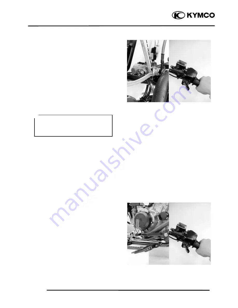
DELAY VALVE BLEEDING
1.
Connect a transparent hose to the bleed
valve (delay valve).
2.
Fully apply the front brake lever after
continuously pull it several times. Then,
loosen the bleed valve nut (delay valve)
to bleed air between the front brake
master cylinder and the delay valve.
3.
Repeat these steps until between the
front brake master cylinder and the delay
valve is free of air. Then tighten the
bleed valve nut.
Torque:
0.6 kgf-m (6 Nm, 4.32 lbf-ft)
COMBINATION BRAKE SYSTEM AIR
BLEEDING
1.
To finish delay valve bleeding (refer to
above).
2.
Connect a transparent hose to the rear
caliper (combined) and front calipers
bleed valves.
3.
Fully apply the brake pedal after
continuously depress it several times and
fully apply the front brake lever after
continuously pull it several times. Then,
loosen the rear caliper bleed valve nut to
bleed air from the brake system.
4.
Fully apply the brake pedal after
continuously depress it several times and
fully apply the front brake lever after
continuously pull it several times. Then,
loosen the front right caliper bleed valve
nut to bleed air from the brake system.
5.
Fully apply the brake pedal after
continuously depress it several times and
fully apply the front brake lever after
continuously pull it several times. Then,
loosen the front left caliper bleed valve
nut to bleed air from the brake system.
When bleeding air from the brake system,
the brake fluid level should be kept over
1/2 of the brake reservoir height (front
brake lever).
*
Bleed Valve
Summary of Contents for MXU 500
Page 1: ...OWNER S MANUAL KWANG YANG MOTOR CO LTD MXU 500 ON ROAD Issued 01 31 2006...
Page 2: ......
Page 85: ...RIDING YOUR ATV 75...
Page 166: ......
Page 212: ...2 FRAME COVERS EXHAUST MUFFLER 2 1 MXU 500...
Page 262: ...4 LUBRICATION SYSTEM 4 1 MXU 500 LUBRICATION SYSTEM DIAGRAM...
Page 279: ...5 FUEL SYSTEM 5 1 MXU 500...
Page 300: ...6 COOLING SYSTEM 6 1 MXU 500 SYSTEM FLOW PATTERN...
Page 331: ...8 CYLINDER HEAD VALVES 8 1 MXU 500 SCHEMATIC DRAWING...
Page 361: ...9 CYLINDER PISTON 9 1 MXU 500 SCHEMATIC DRAWING...
Page 371: ...10 DRIVE PULLEY DRIVEN PULLEY CLUTCH 10 1 MXU 500 SCHEMATIC DRAWING...
Page 398: ...11 FINAL REDUCTION TRANSMISSION SYSTEM 11 1 MXU 500...
Page 427: ...12 LEFT CRANKCASE CRANKSHAFT BALANCE SHAFT 12 1 MXU 500...
Page 434: ...13 DRIVE TRAIN 13 1 MXU 500 FRONT DRIVE REAR DRIVE...
Page 499: ...14 FRONT WHEEL FRONT SUSPENSION STEERING SYSTEM 14 1 MXU 500...
Page 533: ...15 REAR WHEEL AXLE SHOCK ABSORBER SWING ARM 15 1 MXU 500...
Page 553: ...16 BRAKE SYSTEM 16 1 MXU 500...
Page 614: ...18 IGNITION SYSTEM 18 1 MXU 500 IGNITION SYSTEM LAYOUT...
Page 615: ...18 IGNITION SYSTEM 18 2 MXU 500 IGNITION CIRCUIT ON ROAD OFF ROAD...
Page 622: ...19 STARTER SYSTEM 19 1 MXU 500 STARTING SYSTEM LAYOUT...
Page 623: ...19 STARTER SYSTEM 19 2 MXU 500 STARTING CIRCUIT ON ROAD OFF ROAD...
Page 638: ...19 STARTER SYSTEM 19 17 MXU 500 Pull the rope and check that the ratchet is pushed out...
Page 659: ...21 WIRING DIAGRAMS 21 0 MXU 500 21 21...
Page 660: ...21 WIRING DIAGRAMS 21 1 MXU 500...
Page 661: ...21 WIRING DIAGRAMS 21 0 MXU 500 21 21...
Page 662: ...21 WIRING DIAGRAMS 21 1 MXU 500...


