background image


5047 SERIES INSTRUCTION MANUAL 

No. 205-03-325

106-03-004 

©

 2018 KYOCERA Corporatio

n


PAGE 8/9


3-5.  プリント基板およびメタルマスク開口部推奨寸法について 

PCB AND RECOMMENDED DIMENSIONS OF THE OPENING AREA IN THE METAL MASK 

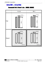
本コネクターは、ピッチ間隔が 0.5mm であり、高密度実装が要求されるコネクターとなっております。  高密度
実装が要求されるコネクターに関しては、半田ブリッジによるショート等の実装不具合を減らすために適正な
はんだ量の管理が必要となります。  つきましては、添付推奨寸法図をご参考願います。  (プリント基板寸
法の詳細につきましては、弊社製品図面をご参照ください) 
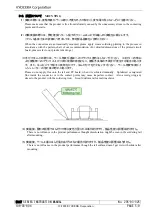
特に、PLUG 保持金具部の半田量が多い場合は RECE ソケットと干渉し、不完全嵌合の原因となりますので
注意ください。 


This  series  of  connector  is  required  to  be  mounted  in  the  high  density  due  to  its  0.5mm  pitches.    The 
connectors mounted in the high density need to be controlled adequate amount of solder in order to prevent 
failures  in  the  mounting  process  such  as  short-circuit  caused  by  solder  bridge.    For  the  dimensions  of  the 
metal mask opening, therefore, please refer to our recommended dimensions shown in the attached drawing. 
(For detailed dimensions of the printed circuit board, please refer to our product drawings.) 
If  excessive  solder  is  applied  on  the  retaining  metal  of  the  plug  connector,  especially,  it  interferes  with  the 
receptacle connector, which leads to incomplete mate of the connectors. 


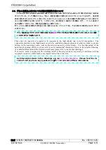
As dimensions shown in the drawings are our 

recommendations

.  Please feel free to 

contact us if you have any questions and

or concerns about these dimensions. 

プリント基板およびメタルマスク開口部寸法は

推奨

ですので不明点や懸念点等がございましたらご相談

いただけますようお願いします。


Summary of Contents for 5047 Series

Page 1: ... 205 03 325 取扱説明書 INSTRUCTION MANUAL 5047Series 0 5mm PITCH Board to Board Connector A DCN18980 2018 11 28 H Sawaki A Tsunemura K Yamane O EDN 18015 2018 01 18 H Sawaki A Tsunemura K Yamane NO EDN DCN DATE PREPARED by CHECKED by APPROVED by ...

Page 2: ...AMES AND MODEL NUMBERS 2 2 1 部品名称 MOUNTING ON THE BOARD 2 2 2 型番 MODEL NUMBERS 3 3 取り扱い上の注意 PRECAUTIONS IN HANDLING 4 3 1 基板対基板嵌合での使用について USING FOR BOARD TO BOARD CONNECTION 4 3 2 実装について MOUNTING 5 3 3 嵌合について ENGAGEMENT 6 3 4 洗浄について CLEANSING 7 3 5 プリント基板およびメタルマスク開口部推奨寸法について PCB AND RECOMMENDED DIMENSIONS OF THE OPENING AREA IN THE METAL MASK 8 ...

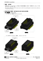
Page 3: ...化に対応すべく開発された 0 5mm ピッチの ボードツーボードコネクターです 5047 Series connector is a board to board connector with 0 5mm pitch designed to miniaturize outer dimension for high density mounting 2 部品名称および型番 PART NAMES AND MODEL NUMBERS 2 1 部品名称 PART NAMES 1 プラグ Plug 型番 10 5047 xxx xxx xxx x 2 リセプタクル Receptacle 型番 20 5047 xxx xxx xxx x 金具有り 金具無し 金具有り 金具無し ...

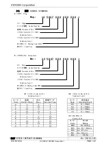
Page 4: ...ル Receptacle Rec 2 4 5 0 4 7 X X X X X X X X X 24 Rec シリーズ番号 Series Number 極数 Number of Pos バリエーションコード 1 1 Variation Code 1 バリエーションコード 2 2 Variation Code 2 めっきコード Plating Code 3 鉛フリー Lead Free 1 バリエーションコード 1 Variation Code 1 2 バリエーションコード 2 Variation Code 2 0 1 2 3 4 5 6 7 8 9 吸着テープ Vacuum Tape ボス Boss 金具 Anchor Plate コード Code H 3 5mm 50 H 5 0mm 60 H 6 0mm 70 H 7 0mm 嵌合高さ Stacking Height コード Code 0...

Page 5: ...ations in dimensions of such as screw holes So great attention should be given not to twist connectors when fixing the boards 2 コネクターが基板に対してセンターに実装されない場合 もしくは大きい基板同士の嵌合の場合に嵌 合が傾く恐れがありますので 下図のような傾き防止用のスペーサーおよび嵌合方向への押さえに よる固定をお勧めします When connectors are mounted off center of the printed circuit board or when the printed circuit boards to be connected are rather large mating may tilt In order to avoid...

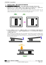
Page 6: ...oduct drawings 3 手付けはんだの際には テール部及び基板へのフラックス塗布はしないでください コネクター内部お よび接触部へのフラックス上がり及び飛散の原因となり 接触不良等の不具合が発生する場合がありま す また はんだごてで端子に負荷をかけて はんだ付けを行わないでください テール部変形及びイ ンシュレーターの溶け等の恐れがあります Please do not apply flux onto the tail and PC board when it is soldered manually Splattered or migrated flux inside the connector or to the contact points may cause imperfect contact Also avoid giving any stress to the pro...

Page 7: ...ign object the spring could be deformed 2 過度なこじり挿抜やねじり挿抜はしないでください 本製品は小型化 軽量化のために成形品の肉厚を 薄くしているため 成形品の破壊 端子の変形 テール部はんだ剥離の原因となります We minimized the thickness of this product to achieve downsizing and light weightiness Because of this uneven pressure or distorted attachment at engagement disengagement could cause destruction terminal deformity plating detachment on the tail こじり Uneven Pressure ねじり Di...

Page 8: ...85 時間 60 秒間 120 秒間 60 秒間 10 分間 Test Condition for Resistance to Solvent Solvent PINE ALPHA ST 100S ARAKAWA CHEMICAL INDUSTRIES LTD Content POLYETHYLENE GLYCOL solvent classified as ALKYL ETHER Content Ratio 80 NON ION SYSTEM SURFACE ACTIVE AGENT Content Ratio 15 PURE WATER Content Ratio 05 Cleansing Process and Condition Process Cleansing Washing Drying Wiping Drying System Up and Down Movement in...

Page 9: ...ity need to be controlled adequate amount of solder in order to prevent failures in the mounting process such as short circuit caused by solder bridge For the dimensions of the metal mask opening therefore please refer to our recommended dimensions shown in the attached drawing For detailed dimensions of the printed circuit board please refer to our product drawings If excessive solder is applied ...

Page 10: ... MANUAL No 205 03 325 106 03 004 2018 KYOCERA Corporation PAGE 9 9 Series 5047 0 5 mm Pitch Recommended Pad Stencil size SIGNAL CONTACT PLUG REC Pad Stencil 0 3mm 2 0mm 0 3mm 2 0mm 0 27mm 1 8mm 0 27mm 1 8mm t 0 15mm t 0 15mm ...

Reviews: