background image

KYOCERA Corporation 


SERIES 7129 INSTRUCTION MANUAL 

 No.:205-03-305 

106-03-004 

PAGE 9/12 

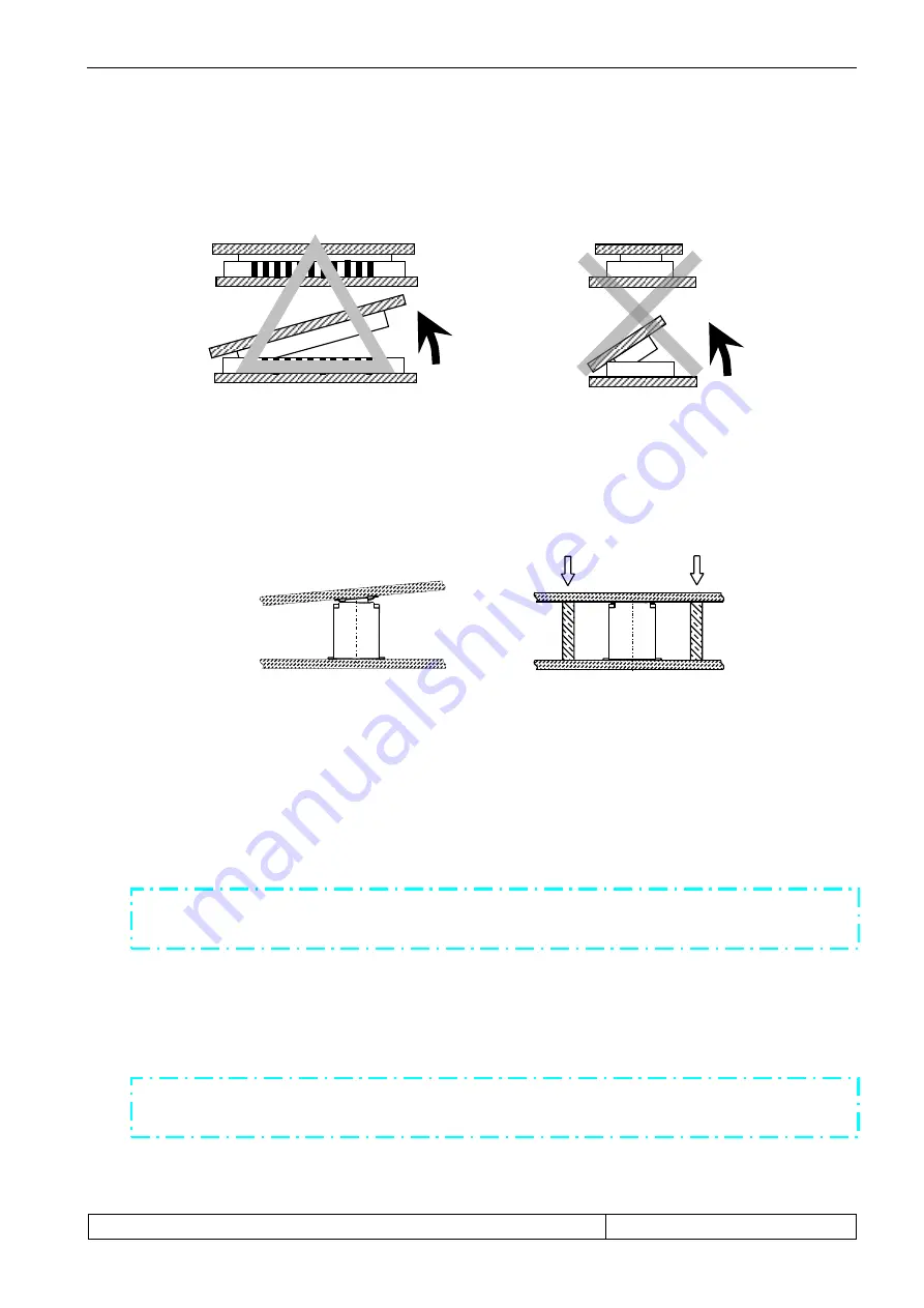
万が一こじり抜去を行う必要がある場合は、長手方向に行って下さい。但し、長手方向への作業は、


こじる側の実装基板・

FPC

厚みにより、コネクタが山反り方向に変形、または、破損する場合が


あります。事前にご確認の上、作業を行って下さい。


If  it  is  required  to  unmate  connectors  with  uneven  pressure,  apply  such  pressure  to  the  long  side  of  the 
connector.  Applying  the  uneven  pressure  to  the  long  side  of  the  connector  may  cause  doomed  warpage  or 
destruction  on  the  connector  depending on  the PCB/FPC  thickness.  Please  make  sure  beforehand


when  you 

apply the uneven pressure to the long side of the connector. 


                    長手方向  (△)                                  短手方向  (×)


(3)


  本製品はコネクタのみでの基板保持は出来ません。押さえが無い場合、嵌合のはずれ、テール 

はんだ剥離、接触不安定が懸念されます。スペーサーなどをご使用頂き、ねじ止めなどの嵌合固定が必要です。 

The connector is impossible to support the PCB by itself. Without other supporting objects, imperfect mating , 
peeling of tails or contacting failure may be caused. As supporting objects, use spacers fixed by screws. 


3-5.  プリント基板およびメタルマスク開口部推奨寸法について 

PCB AND RECOMMENDED DIMENSIONS OF THE OPENING AREA IN THE METAL MASK


本コネクタは、高密度実装が要求されるコネクタとなっております。   
高密度実装が要求されるコネクタに関しては、半田ブリッジによるショート等の実装不具合を減らす 
ために適正なはんだ量の管理が必要となります。  つきましては、添付推奨寸法図をご参考願います。 
  (プリント基板寸法の詳細につきましては、弊社製品図面をご参照下さい。) 


This series of connector is required to be mounted in the high density.   
The connectors mounted in the high density need to be controlled adequate amount of solder in order 
to prevent failures in the mounting process such as short-circuit caused by solder bridge. For the dimensions of   
the metal mask opening, therefore, please refer to our recommended dimensions shown   
in the attached drawing.   
(For detailed dimensions of the printed circuit board, please refer to our product drawings.) 


As dimensions shown in the drawings are our 

recommendations

.    Please feel free to 

contact us if you have any questions and

or concerns about these dimensions. 


NG 

OK 

プリント基板およびメタルマスク開口部寸法は

推奨

ですので、不明点や懸念点等がございましたら、


ご相談頂けますようにお願いします。


Summary of Contents for 7129 Series

Page 1: ... 取 扱 い説 明 書 INSTRUCTION MANUAL Series 7129 Battery Board to Board Connector A DCN 1146 2016 12 21 H Watanabe A Tsunemura K Yamane O EDN 522 2015 10 30 S Asai A Tsunemura T Sasaki No EDN DCN DATE PREPARED by CHECKED by APPROVED by ...

Page 2: ... NUMBERS 3 3 取り扱い上の注意 PRECAUTIONS IN HANDLING 4 3 1 基板対基板嵌合での使用について USING FOR BOARD TO BOARD CONNECTION 4 3 2 基板対FPC嵌合での使用について USING FOR BOARD TO FPC CONNECTION 5 3 3 実装について MOUNTING 6 3 4 嵌合について ENGAGEMENT 8 3 5 プリント基板およびメタルマスク開口部推奨寸法について PCB AND RECOMMENDED DIMENSIONS OF THE OPENING AREA IN THE METAL MASK 9 3 6 活線挿抜について HOT SWAP 11 3 7 推奨吸着ノズル寸法について RECOMMENDED DIMENSIONS OF THE PICK UP NOZZLE 1...

Page 3: ...nector is a battery board to board connector designed to miniaturize outer dimension for high density mounting 2 部品名称および型番 PART NAMES AND MODEL NUMBERS 2 1 部品名称 PART NAMES 1 プラグ Plug 2 リセプタクル Receptacle アンカープレート Anchor Plate アンカープレート Anchor Plate シグナルコンタクト Signal Contact インシュレータ Insulator インシュレータ Insulator パワーコンタクト Power Contact シグナルコンタクト Signal Contact パワーコンタクト Power Contact ...

Page 4: ...番 MODEL NUMBERS 1 プラグ Plug Plug 14 7129 002 001 829 14 Plug シリーズ番号 Series Number 極数 Number of Pos バリエーション Variation めっきコード Plating Code 鉛フリー Lead Free 2 リセプタクル Receptacle Rec 24 7129 002 001 829 24 Rec シリーズ番号 Series Number 極数 Number of Pos バリエーション Variation めっきコード Plating Code 鉛フリー Lead Free ...

Page 5: ...ions in dimensions of such as screw holes So great attention should be given not to twist connectors when fixing the boards 2 コネクタが基板に対してセンターに実装されない場合 もしくは大きい基板同士の嵌合の場合に 嵌合が傾く恐れがありますので 下図のような傾き防止用のスペーサーおよび嵌合方向への押さえ による固定をお勧めします When connectors are mounted off center of the printed circuit board or when the printed circuit boards to be connected are rather large mating may tilt In order to avoid ti...

Page 6: ...from the stress caused by connector insertion extraction Such reinforcing board should be bigger than our product and its suitable thickness should be decided through actual test In addition the thickness of FPC reinforcing board recommends 0 3mm or more from our check result Our condition is FPC 0 1mm heat adhesive line 0 05mm SUS Supporting Tape 0 15mm 2 落下 衝撃や FPC 取り回しの際の反力が大きく加わることが懸念される場合はコネク...

Page 7: ...0 10mm をお勧め致します 0 10mm is recommended for the thickness of screen of the cream solder printing 4 実装条件が弊社推奨リフロー温度プロファイル条件と異なる場合は あらかじめ実装後に コネクタの変形 変色が無いことをご確認の上 実装を行って下さい When the mounting condition differs from those of our profile in any way please make sure that you do not observe any deformity nor discoloration with the mounted connector beforehand 5 N2 リフローによるはんだ付けは O2 濃度が 1000ppm 程度で下記に示す弊社リフ...

Page 8: ...giving any stress to the product with the soldering iron It could deform tail or melt insulator 8 実装後 酸化の影響ではんだ付け部に変色が見られる事がありますが 製品性能に影響はありません There is no influence in the product performance thought discoloration might be seen in the soldering tail after mounting 9 実装後 テール上面にはんだ濡れ広がりのない場合がありますが 製品性能に影響はありません There is no influence in the product performance though the tail surface doesn t get wet...

Page 9: ...ould be deformed 2 本製品は小型 軽量化をする為に成形品の肉厚を薄くしており 嵌合 離脱時に過度なこじり ねじり挿 抜は成形品の破壊 端子の変形 テール部はんだ剥離の原因となりますので ご注意をお願い致します We minimized the thickness of this product to achieve downsizing and light weightiness Because of this uneven pressure or distorted attachment at Insertion separation could cause destruction terminal deformity plating detachment on the tail こじり Uneven Pressure ねじり Distorted Attachment ...

Page 10: ...ay be caused As supporting objects use spacers fixed by screws 3 5 プリント基板およびメタルマスク開口部推奨寸法について PCB AND RECOMMENDED DIMENSIONS OF THE OPENING AREA IN THE METAL MASK 本コネクタは 高密度実装が要求されるコネクタとなっております 高密度実装が要求されるコネクタに関しては 半田ブリッジによるショート等の実装不具合を減らす ために適正なはんだ量の管理が必要となります つきましては 添付推奨寸法図をご参考願います プリント基板寸法の詳細につきましては 弊社製品図面をご参照下さい This series of connector is required to be mounted in the high density The connect...

Page 11: ...G REC Pad Stencil t 0 1mm PLUG REC Pad Stencil t 0 1mm S Se er ri ie es s 7 71 12 29 9 Recommended Pad Stencil size SIGNAL CONTACT 0 24mm 0 485mm 0 24mm 0 485mm 0 22mm 0 485mm 0 22mm 0 485mm Recommended Pad Stencil size POWER CONTACT 1 13mm 0 485mm 0 8mm 0 485mm 0 8mm 0 485mm 1 13mm 0 485mm ...

Page 12: ...ad Stencil t 0 1mm 3 6 活線挿抜について Hot Swap 本製品に電流を流した状態での挿抜は なさらないよう御願い致します Insertion and separation under live current shall not be done S Se er ri ie es s 7 71 12 29 9 Recommended Pad Stencil size ANCHOR PLATE 0 4mm 1 1mm 0 6mm 0 38mm 0 24mm 0 35mm 0 4mm 0 33mm 0 38mm 0 24mm 0 35mm 0 33mm 0 6mm 0 4mm 0 4mm 1 1mm ...

Page 13: ... 305 106 03 004 PAGE 12 12 3 7 推奨吸着ノズル寸法について RECOMMENDED DIMENSIONS OF THE PICK UP NOZZLE 推奨吸着ノズル寸法は以下の通りです The following is the recommended dimensions of the pick up nozzle コネクタが基板上に有る際の最大加圧荷重 20N Maximum pressure when the connector is placed on a PCB 20N 2 2 8 ...

Reviews: