background image

2RG/2RH

1-3-130

Contents

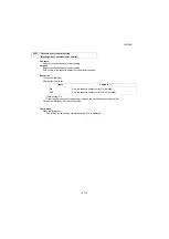
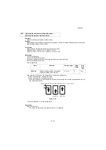
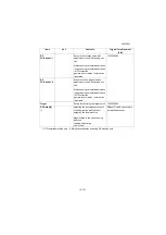
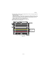
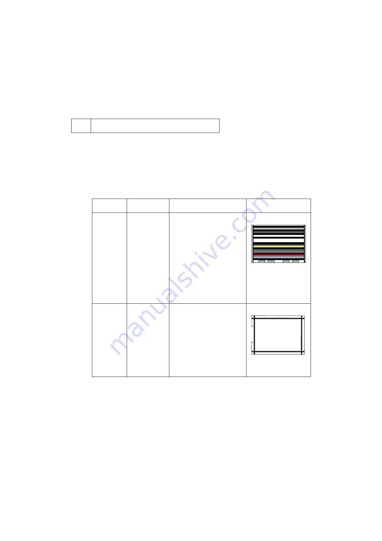
Uses the specified originals and automatically adjusts the following items in the scanner and the DP scan-
ning sections.
Scanner section:Original size magnification, leading edge timing, center line, chromatic aberration in main/
sub scanning direction, MTF correction, color/monochrome input gamma, color correction matrix automatic 
adjustment
DP scanning section: Original size magnification, leading edge timing and center line, MTF correction, Input 
gamma, automatic adjustment of color correction matrix

Purpose

Automatically adjusts the scanner and the DP scanning sections.

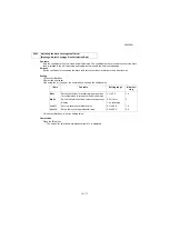
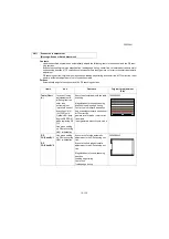
U411

Scanner auto adjustment
(Message: Scanner Auto Adjustment)

Items

Use

Contents

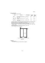
Original for adjustment

(P/N)

Table (Chart 
A)

In case of losing 
adjustment data, 
differing from the 
color tone 
extremely (not 
improve in case of 
executing U410)   
ISU(CCD unit), 
Optical LED lamp, 
Engine EEPROM, 
when replacing DP 
CIS
Use when setting 
up DP or executing 
U021 initialization

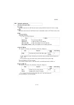
Execute automatic adjusts the table 
scanning.

Magnification in the sub scanning 
direction / Leading edge timing
Center line / chromatic aberration
Sub scanning chromatic aberration / 
MTF correction
gamma in color mode / color correc-
tion matrix
Input gamma in monochrome mode

7505000005

DP 
FU(ChartB) *1
 
DP 
FD(ChartB) *2

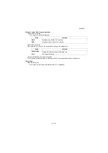
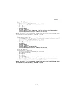
Use when setting 
up DP or executing 
U021 initialization

Execute the 1st side automatic 
adjustment in the DP scanning sec-
tion.
Execute the 2nd side automatic 
adjustment in the DP scanning sec-
tion.

Magnification in the sub-scanning 
direction
Leading edge timing
Center line
Trailing edge timing

302AC68243

COL OR SCANN ER

CH ART A4

N o.302K 357010

Summary of Contents for Copystar CS 3011i

Page 1: ...SERVICE MANUAL Published in September 2016 2RHSM 1 Rev 1 6 3011i 6 3511i ...

Page 2: ...TERIE EST REMPLACEE PAR UN MODELE DE TYPE INCORRECT METTRE AU REBUT LES BATTERIES UTILISEES SELON LES INSTRUCTIONS DONNEES Il peut être illégal de jeter les batteries dans des eaux d égout municipales Vérifiez avec les fonctionnaires municipaux de votre région pour les détails concernant des déchets solides et une mise au rebut appropriée Notation of products in the manual For the purpose of this ...

Page 3: ... 23 Change Add the connector holder 1 3 15 1 3 17 Correction Option Description Modify hard disk added 1 3 33 Correction Change the description of switch in U031 1 3 181 Correction U671 DIMM STORAGE 1 5 57 1 5 58 Correction Notes when replacing the main PWB 1 5 63 Added Notes when replacing the engine PWB 1 5 77 to 79 Added Detaching and reattaching the SSD ...

Page 4: ...This page is intentionally left blank ...

Page 5: ...rsonnel to ensure the safety of their customers their machines as well as themselves during maintenance activities Service personnel are advised to read this booklet carefully to familiarize themselves with the warnings and precautions described here before engaging in maintenance activities ...

Page 6: ... this symbol CAUTION Bodily injury or damage to property may result from insufficient attention to or incorrect com pliance with warning messages using this symbol Symbols The triangle symbol indicates a warning including danger and caution The specific point of attention is shown inside the symbol General warning Warning of risk of electric shock Warning of high temperature indicates a prohibited...

Page 7: ...d or dusty place This may cause fire or electric shock Do not install the copier near a radiator heater other heat source or near flammable material This may cause fire Allow sufficient space around the copier to allow the ventilation grills to keep the machine as cool as possible Insufficient ventilation may cause heat buildup and poor copying performance Always handle the machine by the correct ...

Page 8: ... carefully Always check that the copier is correctly connected to an outlet with a ground connection Check that the power cable covering is free of damage Check that the power plug is dust free If it is dirty clean it to remove the risk of fire or electric shock Never attempt to disassemble the optical unit in machines using lasers Leaking laser light may damage eyesight Handle the charger section...

Page 9: ... caution labels that should be present on the machine according to the instruction handbook are clean and not peeling Replace with new ones if necessary Handle greases and solvents with care by following the instructions below Use only a small amount of solvent at a time being careful not to spill Wipe spills off completely Ventilate the room well while using grease or solvents Allow applied solve...

Page 10: ...This page is intentionally left blank ...

Page 11: ...rd Except 100V model 1 2 30 9 Coin Vendor installation 100V model only 1 2 35 10 card reader installation 1 2 38 11 Handset attaching 1 2 41 11 1 When attaching the main unit directly 1 2 41 11 2 In case installing the document table 1 2 45 1 2 5 About Optional Applications 1 2 54 1 2 6 Initializing procedures after installing the FAX system 1 2 55 1 3 Maintenance mode 1 3 1 Maintenance mode 1 3 1...

Page 12: ...age reception error 1 4 92 2 5 U010XX error code table G3 transmission 1 4 93 2 6 U011XX error code table G3 reception 1 4 95 2 7 U017XX error code table V 34 transmission 1 4 96 2 8 U018XX error code table V 34 reception 1 4 97 2 9 U023XX error code table Relay command abnormal reception 1 4 97 2 10 U044XX error code table Encrypted transmission 1 4 97 1 5 Assembly and disassembly 1 5 1 Precautio...

Page 13: ... 5 10 PWBs 1 5 54 1 Detaching and reattaching the main PWB 1 5 54 1 1 Notes when replacing the main PWB 1 5 57 2 Detaching and reattaching the engine PWB 1 5 59 2 1 Notes when replacing the engine PWB 1 5 63 3 Detaching and reattaching the power source PWB 1 5 64 4 Detaching and reattaching the high voltage PWB 1 5 66 5 Detaching and reattaching the operation panel PWB 1 1 5 70 1 5 11 Others 1 5 7...

Page 14: ...ance kits 2 4 2 3 Periodic maintenance procedures 2 4 3 4 Repetitive defects gauge 2 4 6 5 Firmware environment commands 2 4 7 6 System Error Fxxxx Outline 2 4 18 7 Chart of image adjustment procedures 2 4 25 8 Wiring diagram 2 4 28 Installation Guide DP 7100 Document processor DP 7110 Document processor DP 7120 Document processor PF 791 500 x 2 Paper feeder PF 810 3000 sheet deck DF 791 3000 shee...

Page 15: ... R Executive Oficio II Folio 8K 16K R 16K ISO B5 Envelope 10 Envelope 9 Envelope 6 Envelope Monarch Envelope DL Envelop C5 Envelope C4 Hagaki Cardstock Oufuku Hagaki Return postcard Youkei 4 Youkei 2 Custom 1 to 4 98 148 mm to 297 432 mm Printable Area The point 3 2 5 mm The back point 3 2 5 mm left right less than 4 mm Warm up Time 23 C 60 RH Power on 18 seconds or less Low Power 15 seconds or le...

Page 16: ...protection devices thermostat Memory 2 0GB Large capacity storage SSD 32GB SSD 8 GB Hard Disk 320GB Inter Interface Standard USB Interface Connector 1 Hi Speed USB 3 Network interface 1 10 BASE T 100 BASE TX 1000 BASE T Hi Speed USB 4 USB Flash memory slot Option eKUIO 2 2 Fax 2 3 Wireless LAN 1 Operating Environment Temperature 10 to 32 5 C 50 to 90 5 F Humidity 15 to 80 RH Above the sea level 2 ...

Page 17: ...n 24 sheets min A5R 15 sheets min 17 sheets min First Copy Time The main unit cassette paper feed A4 Less than 3 6 seconds Except the system safety time after the main power switches on Zoom Level Manual mode 25 to 400 1 increments Fixed zoom rate 400 200 141 122 115 100 86 81 70 50 25 Continuous Copying 1 to 999 sheets Resolution 600 600 dpi 9600 dpi equivalent 600 dpi Supported Original Types Sh...

Page 18: ... Windows 8 1 Windows 10 Windows Server 2008 R2 Windows Server 2012 R2 Mac OS 10 5 or later Interface USB Interface Connector 1 Hi Speed USB Network interface 1 1000 BASE T 100 BASE TX 10 BASE T IPv6 IPv4 IPSec 302 3az sup ported Optional Interface Option 2 For IB 50 IB 51 mounting Wireless LAN Option 1 For IB 35 mounting Page Description Language PRESCRIBE Emulations PCL6 PCL XL PCL 5c KPDL3 PostS...

Page 19: ... sided 50 to 220 g m Loading Capacity 140 sheets maximum 50 to 80 g m2 1 50 sheets maximum 50 to 80 g m2 1 270 sheets maximum 50 to 80 g m2 1 Dimensions Dimension W D H 593 531 138 5 mm 23 35 20 91 5 46 600 502 128 mm 23 35 20 91 5 46 600 513 170 mm 23 35 20 91 5 46 Weight Approx 9 kg Approx 7 5 kg Approx 14 5 kg Items Specifications Paper Supply system Feed reverse roller system Store Sheets 550 ...

Page 20: ... 340 mm Ledger Legal Statement R Executive Oficio II Folio 8K 16K R 500 sheets A4 R A4 B5 B6 R Letter R Letter 16K 1 000 sheets Paper thickness When stapling 90 g m or less Stapling Number of sheets to limit A3 B4 B5 R 216 340 mm Ledger Legal Oficio II 16K R 8K 30 sheets 52 to 105 g m 2 cover sheets only 106 to 300 g m A4 R A4 B5 Letter R Letter 16K 50 sheets 52 to 90 g m 40 sheets 91 to 105 g m 2...

Page 21: ...fuku Hagaki Return postcard Cus tom 98 148 mm to 297 432 mm 200 sheets Paper thickness When stapling 90 g m or less Stapling Number of sheets to limit A3 B4 B5 R 216 340mm Ledger Legal Oficio II 8K 16K R 30 sheets 52 to 105 g m 2 cover sheet only 106 to 256 g m A4 R A4 B5 Letter R Letter 16K 70 sheets 52 to 74 g m 65 sheets 75 to 90 g m 55 sheets 91 to 105 g m 2 cover sheet only 106 to 256 g m Med...

Page 22: ...B5 Ledger Letter R Letter Legal State ment R Folio 8K 16K R 16K Paper thickness 45 to 300 g m2 Media type Plain Preprinted Bond Recycled Letterhead Color Thick Coated High Quality Custom 1 to 8 Items Specifications Number of Trays 7 trays Paper Size 80 g m A3 B4 Ledger Legal 50 sheets A4 R A4 A5 R B5 R B5 B5 R B5 216 340 mm Letter R Letter State ment R Oficio II Folio 8K 16K R 16K Dimensions W D H...

Page 23: ...unit Front side Figure 1 1 1 7 1 3 2 2 8 4 5 6 6 10 9 11 1 Cassette 2 Paper Width Guides 3 Paper Length Guide 4 MP Tray 5 MP sub tray 6 MP Paper Width Guides 7 Inner Tray 8 Operation Panel 9 USB Memory Slot 10 Main Power Switch 11 Power switch ...

Page 24: ...12 15 22 12 Toner waste box 13 Toner waste box Spare 14 Front Cover 15 Right Cover 1 16 Right Cover 2 17 Transfer roller 18 Diverge guide 19 Fuser unit 20 Toner Container 21 Drum unit 22 Developer unit 23 Toner Container lever 24 Developer Stopper 25 Developer lever ...

Page 25: ...34 36 26 28 26 DP link connector cover 27 Scanner lock cover 28 Coin vendor connector 29 Cassette heater switch 30 Inlet connector 31 Option Interface Slot 2 32 Option Interface Slot Slot 1 33 Network interface Connectors 34 USB port 35 USB Interface Connector 36 SD card slot ...

Page 26: ...stem Menu screen 8 Reset key Returns settings to their default states 9 Stop key Cancels or pauses the job in progress 10 Start key Starts copying and scanning operations and processing for setting operations 11 Interrupt key Displays the Interrupt Copy screen 12 Authentication Logout key Authenticates user switching and exits the operation for the current user i e log out 13 Energy Saver key Puts...

Page 27: ...te 1 2 Cassette 1 paper feed sec tion 3 Cassette 2 4 Cassette 2 paper feed sec tion 5 Multi Purpose paper feed section 6 Conveying section 7 Transfer Separate section 8 Charger roller unit 9 Drum unit 10 Developer unit 11 Toner Container 12 Fuser unit 13 Eject section 14 Dual conveying section 15 Image Scanner Unit ISU 16 Laser Scanner Unit LSU ...

Page 28: ...ons where cool wind and hot wind expose directly Avoid the locations with dust and much vibration When setting on the stand use the stand which can sufficiently endure in the machine weight Set the horizontal location Horizontal degree Left and right front and rear are 5mm or less Twisting is 3mm or less Avoid the locations where the substances which can be transformed the machine and the photorec...

Page 29: ...t out the user setting list Execution of initial setting operation Execution of mentenance item U952 Set cassette heater control maintenance item U327 Setting the delivery date maintenance item U278 Completion of the machine installation Switch the cassette heater switch Install the other optional devices Clearing the counter maintenance item U927 Output an own status report maintenance item U000 ...

Page 30: ...13 11 Machine unpacking 1 Skid 2 Hinge 3 Bottom pad right front 4 Bottom pad right rear 5 Bottom pad left front 6 Bottom pad left rear 7 Bottom pad center 8 Plastic bag 9 Accessory box 10 Inner pad front left 11 Inner pad front right 12 Inner pad rear 13 Stay 14 Outer case 15 Main unit 16 Plastic bag 17 Upper pad 18 Install guide etc 19 Plastic bag 20 Power cord ...

Page 31: ...the main unit Figure 1 2 3 4 Peel off two tapes and remove the pro tective operation cover 5 Peel off the protective panel sheet 6 Peel off the tape of the scanner lock section Figure 1 2 4 Tape Protective PAD Tapes Tape Tapes Paper Tape Protective sheet Protective panel sheet Protective operation cover Tape Tape Tape Removal of the fixed tape and the spacer ...

Page 32: ...d if you want to see the detail Figure 1 2 5 1 Pull out the paper storage bag 2 Hold the switch knob of the wide size adjust the paper width guide on the paper width Figure 1 2 6 Paper feeder Main body Cassette Paper width adjusting tab Paper width guides Paper preservation bag Paper Feeder installment Loading Paper ...

Page 33: ...st the paper length guide on the paper length Figure 1 2 7 4 Set the paper in the cassette 5 Insert the cassette size plate 6 Push in quietly the cassette Figure 1 2 8 Paper length guide Paper Cassette Cassette size plate ...

Page 34: ...ive times Reverse high and low beat the upper section more than five times Figure 1 2 9 3 Turn the toner container vertically shake the upper section more than five times Reverse high and low shake the upper section more than five times Figure 1 2 10 Toner container Toner container Toner Container installment ...

Page 35: ...hake the toner container in sideways five or six times Figure 1 2 11 5 Push in the toner container along the guide of the main unit Push in the back till being locked Figure 1 2 12 Toner container Toner container CLICK ...

Page 36: ...Input 10871087 using the numeric keys and set the maintenance mode Input 327 using the numeric keys and press the Start key Select On or Off and press the Start key Press the Stop key Precaution for Loading Paper If paper is left in the cassette for a long period heat from the cassette heater may discolor it 1 In case of installing the other optional equipment finisher fax kit etc install respecti...

Page 37: ...sing the lock the error mes sage C3100 is displayed when input ting the power source Figure 1 2 14 1 Connect the power cord to the main unit and the outlet 2 Fix the ground terminal of the power cord to the ground near the outlet by the screw Figure 1 2 15 Scanner lock cover Flat screw driver Scanner lock cover Locked Released Power code Wall ooutlet Connecting the Power Cord The release of the sc...

Page 38: ...the numeric keys and set the maintenance mode 2 Input 327 using the numeric keys and press the Start key 3 Select On 4 Press the Start key and determine the setting 5 Press the Stop key Setting the machine delivery date Execution of the maintenance mode U278 1 Input 278 using the numeric keys and press the Start key 2 Select Today 3 Press the Start key and set the machine delivery date 4 Press the...

Page 39: ...ey 1 Select report output from the system menu and can output each setting report of the user 1 Set the originals and test a copy Output each kind of setting report for user The execution of the test copy Install completion of the main unit Release of the maintenance mode ...

Page 40: ... single counts The single counts U260 Switch of the counts of the paper feeding or the paper ejection Eject U265 Destination setting U278 The setting of the delivery date U285 The setting of the service status page On U326 The setting of the black streaks clear display On 8 U327 Cassette heater control setting Off U332 The size coefficient setting Rate Mode Level 1 Level 2 1 0 0 1 0 2 5 U340 The a...

Page 41: ...guration In case of attaching the next option it needs to attach the metal fitting of the fall prevention PF 791 PF 810 1 PLATEN COVER TYPE E 1 DP 7100 2 MT 730 B 4 DF 7120 6 PF 791 7 PF 810 5 PH 7B 1 DP 7110 8 NK 7100 3 DF 791 1 DP 7120 ...

Page 42: ...2RH 1 2 15 Software option 16 Internet FAX Kit A 17 Data Security Kit E 18 UG 33 19 UG 34 20 Scan extension kit A 10 FAX System 12 11 IB 50 12 IB 51 13 IB 35 15 DT 730 B 9 Card Authentication kit B 14 HD 12 ...

Page 43: ...emove the screw M3x8 3 Release the hook in the direction of the arrow and then remove the SD card cover Figure 1 2 16 4 Install an SD SDHC memory card in the memory card slot Figure 1 2 17 5 Reattach the covers Formatting an SD SDHC Memory Card To use an unused SD SDHC card you must first format it with the main unit Formatting will delete all existing data on the SD card If you have installed an ...

Page 44: ...erface cables 2 Detach three screws 3 Open the upper section of the rear upper cover and detach in the direction of the arrow Figure 1 2 18 IMPORTANT Check two gaskets are affixed to the hard disk mounting plate before installing it Figure 1 2 19 Parts Number Parts number Hard Disk HD 12 1 1503RS0UN0 Product Screw Screw Screw Rear upper cover Hard disk mounting plate Gasket Gasket ...

Page 45: ... 18 4 Connect two connectors of the cables to the hard disk 5 Latch two hooks on the aperture and attach the hard disk with four screws M3x8 Figure 1 2 20 Screw Screw Screw Screw aperture Hook Connectors Hard disk ...

Page 46: ... if data exists in the FAX box Formatting a hard disk 1 Input 10871087 using the numeric keys to enter the maintenance mode 2 Input 024 using the numeric keys and press the Start key 3 Select Format 4 Select Full 5 Select Execute 6 Press the Start key to initialize 7 Turn the power switch off then on Wait more than 5 seconds between the power off and on When an optional HDD is inserted into the ma...

Page 47: ... the following parts Procedures 1 After checking to press the power source key put out the power source lamp and memory lamp turn the main power switch OFF and unplug the power plug 2 Detach two pins remove the OPT2 slot cover Figure 1 2 22 Parts Number Parts number Gigabit Ethernet extension kit IB 50 1 1505JV0UN0 Product Parts Number Parts number Wireless LAN interface kit IB 51 1 1505J50UN0 Pro...

Page 48: ...ched in step 2 Do not touch directly to the terminal of the kit PWB In case of inserting the kit PWB hold the top and bottom or the protuberance of the PWB Figure 1 2 23 4 Insert the modular cord into the line ter minal Figure 1 2 24 Pin Gloove Pin Gigabit ethernet board Modular cord ...

Page 49: ...ff the main unit and disconnect the power cord and all interface cables 2 Detach three screws 3 Open the upper section of the rear upper cover and detach in the direction of the arrow Figure 1 2 25 4 Slide the controller box cover in sideways remove it Figure 1 2 26 Parts Number Parts number Wireless LAN interface kit IB 35 1 1503RR0UN0 Product Screw Screw Screw Rear upper cover Controller box cov...

Page 50: ...tor Insert the connector while aligning the white part of the main PWB to the outer shape of the connector holder Figure 1 2 27 7 Attach the WiFi PWB by using one screw 8 Reattach the removed parts in the original position Figure 1 2 28 Connector of main PWB White part Connnector holder Connector of main PWB WiFi PWB Connector Screw ...

Page 51: ...over 1 pc Tray fixing plate 1 pc Sheet 2 pc Pin 2 pc Nut M4 1 2 pc Screw M4x8 screw with the binding head 7 pc Screw M4x14 screw with the binding head 2 pc 1 Not used in this model Procedures 1 Turn the power switch off and disconnect the power plug 2 Attach the tray stay by using two screws Figure 1 2 29 Parts Number Parts number Document table DT 730 B 1 1902LC0UN2 Product Screw Screw Tray stay ...

Page 52: ... the mounting plate into the tray stay by using two screws Figure 1 2 30 4 Attach the tray cover to the tray stay by using four screws Figure 1 2 31 Tray mounting plate Tray stay Screw Screw Screws Screws Tray cover Tray stay ...

Page 53: ...tach the tray lower cover 6 Fix the tray lower cover by using two pins Figure 1 2 32 7 Affix the two sheets on the document table Figure 1 2 33 B B A A Tray lower cover Screw Screw B B A A B B A Document table Sheet Sheet ...

Page 54: ...3x8 2 pc Label 1 pc NK 7100 only Procedures 1 Turn the power switch off and disconnect the power plug 2 Remove one screw from the operation unit 3 Release two hooks and then remove the operation unit lid in the direction of the arrow Figure 1 2 34 Parts Number Parts number Numeric Keypad NK 7100 1 Numeric Keypad NK 7110 2 1 1 1903RT0UN0 Product 1903RT0US0 Product Screw Operation unit lid Hook Hook...

Page 55: ...nector of the operation unit Figure 1 2 35 5 Latch two hooks on the cut out of the operation unit and then attach the numeric keypad by using two screws Figure 1 2 36 Numeric keypad Operation unit connector Connector Hooks Numeric keypad Numeric keypad Cut out Screw Screw ...

Page 56: ... the direction of the arrow and latch two hooks and attach by using one screw which removed in step 2 Figure 1 2 37 7 Affix the label on the numeric keypad Except 120v model Figure 1 2 38 Screw Cover Screw Hook Hook Label Numeric keypad ...

Page 57: ...S tite 1 6 pcs Screws M3x8 S tite Black 2 pcs Screws M3x8 P tite 2 pcs Screws M4x8 S tite 2 4 pcs Screws M4x8 S tite 2 pcs 1 4 pc is used for this model 2 Not used in this model Procedures 1 Turn the power switch off and disconnect the power plug 2 Attach the upper keyboard mounting bracket onto the lower keyboard mounting bracket by using the four screws Align the location of the mark A and attac...

Page 58: ...er Figure 1 2 40 5 Twist in front of the A section of the card reader cover remove to pull in the left direction Figure 1 2 41 6 Remove one screw slide the keyboard cover in the direction of the arrow and remove it Figure 1 2 42 Operation panel lower cover Screw Card reader cover A Keyboard cover Screw ...

Page 59: ...wer keyboard mounting bracket Attach it while the hooks come to the punch mark B Figure 1 2 44 11 Insert two protrusions of the lower cover C two hooks A and three hooks B into the cut out of the lower cover B the aperture and the protrusion of the upper keyboard mounting bracket Figure 1 2 45 Lower keyboard mounting bracket Screw A Screw A Screw B Screw B Apertures Hooks Lower cover B Lower keybo...

Page 60: ... keyboard mounting bracket by using one svrew Attach it while the hooks come to the punch mark B Figure 1 2 47 14 Insert the upper keyboard cover into the upper keyboard mounting plate and attach it Figure 1 2 48 Upper keyboard mounting bracket Screw Screw Lower cover C Screw Lower keyboard mounting bracket Lower cover A Hook Upper keyboard cover Upper keyboard mounting plate ...

Page 61: ...concave of the upper keyboard cover Figure 1 2 50 18 Place the keyboard on the hook and loop fastener and press it to fix 19 Connect the USB cable with the USB connector on the main unit Figure 1 2 51 20 Reattach the removed card reader cover and the below operation panel cover in the original position Upper cover Lower keyboard mounting bracket Screw Hooks Protrusion upper keyboard cover Concave ...

Page 62: ...g washer screw M4x8 1pc Procedures 1 Detach three screws 2 Open the upper section of the rear top cover and detach in the direction of the arrow Figure 1 2 52 3 Detach four screws 4 Open the lower section of the rear top cover and detach in the direction of the arrow Figure 1 2 53 Parts Number Parts number Coin Vendor CV 1 ACV 1 1 Product Screw Screw Screw Rear upper cover Screw Lower rear cover S...

Page 63: ...d in step 5 Figure 1 2 55 8 Attach the ground terminal of the vendor cable to the IF mounting by using one screw M4 8 9 Connect the vendor cable connector to the main unit signal line connector Figure 1 2 56 Screw Concealing lid Screw Screw Screw Vendor cable Aperture of IF mounting Vendor cable connector Screw Ground terminal Vendor cable connector Main unit signal line connector IF mounting ...

Page 64: ... the connector of the vendor wire 12 Turn the power switch on and enter the maintenance mode 13 Execute maintenance mode U206 and set Coin vendor attachment Execute continuously each detail setting See page1 3 84 14 Release the maintenance mode Figure 1 2 57 Signal wire of the coin vendor Vendor wire connector ...

Page 65: ...amp and memory lamp turn the main power switch OFF and unplug the power plug 2 Detach the screw b and remove the operation panel lower cover Figure 1 2 58 3 Twist in front of the A section of the card reader cover remove to pull in the left direction Figure 1 2 59 Parts Number Parts number Card label 1 302ND3423_ Bundled main unit Operation panel lower cover Screw Card reader cover A ...

Page 66: ...on 6 Connect the winding portion Figure 1 2 60 7 Pull the card reader cover a in the right side and attach it 8 Affix the card label b 9 Reattach the operation panel lower cover in the original position Figure 1 2 61 winding portion card reader USB cable winding portion card reader holder Card reader cover Card label ...

Page 67: ...d password and press Login Login with administrator privileges here 3 Press Next to of Optional function 4 Select CARD AUTHENTICATION KIT B and press Start up 5 The screen which enters the license key is displayed Enter the license key by using the numeric keyboard and press Regular using 6 Check the product name CARD AUTHENTICATION KIT B and press Yes 7 In case of using SSFC card execute the main...

Page 68: ...elephone wire 1 pc Modular cord 1 pc Nut M4 2pcs Procedures 1 After checking to press the power source key put out the power source lamp and memory lamp turn the main power switch OFF and unplug the power plug 2 Attach the handset mounting bracket to the right top of the main unit by using two pins Use the lower screw holes of the handset mounting bracket Figure 1 2 62 Parts Number Parts number Ha...

Page 69: ... holder 4 While stretch the telephone wire insert it into the cable guide Figure 1 2 63 5 Put two pins into the catches at the backside of the handset holder slide it toward you and fix it Figure 1 2 64 Cable guide Telephone wire Connector Handset holder Handset holder Pin Pin ...

Page 70: ...ate Figure 1 2 65 7 Connect the telephone wire to the handset Insert the telephone wire into between the handset holder and main unit Figure 1 2 66 Protection cover Handset mounting plate A B A B Telephone wire Handset Handset holder Handset holder Main unit Telephone wire ...

Page 71: ...nnect the modular code to the con nector of the main unit left side Figure 1 2 67 9 Connect the modular cord to the another handset holder Figure 1 2 68 Modular code Connector Main unit A B A B Modular code Handset holder ...

Page 72: ... Protection cover 1pc Pin 2 pcs Telephone wire 1 pc Modular cord 1 pc Nut M4 2pcs Bundled parts of Document table Tray stay 1 pc Tray mounting bracket 1pc Tray cover 1 pc Tray lower cover 1 pc Tray fixing plate 1 pc Sheet 2pcs Pin 1 pc Nut M4 2pcs Screw M4x8 2 pcs Nut M4 7pcs Screw M4x14 2 pcs Parts Number Parts number Handset 1 1909AG9JP0 Product Document table 1 1902LC0UN1 Product B B A A ...

Page 73: ...he power source key put out the power source lamp and memory lamp turn the main power switch OFF and unplug the power plug 2 Attach the tray stay to the scanner right cover by using two screws M4 14 Figure 1 2 69 Scanner right cover Screw Screw Tray stay ...

Page 74: ...2RG 2RH 1 2 47 3 Insert the tray mounting plate into the tray stay and attach by using two screws M4 8 Figure 1 2 70 Screw Screw Tray stay Tray mounting plate ...

Page 75: ...ure 1 2 71 5 Remove two nuts and two pins from the handset mounting plate 6 Attach two removed nuts and two pins to the mark A location of the tray mount ing plate Figure 1 2 72 Screws Tray cover Screws B A B A A B A B A Tray mounting plate Pins Nuts Handset mounting plate Pins Nuts ...

Page 76: ...7 Connect the modular code to the con nector of the main unit left side Figure 1 2 73 8 Connect the modular cord to the another handset holder Figure 1 2 74 Modular code Connector Main unit Modular code Handset holder ...

Page 77: ... at the backside of the handset holder slide it toward you and fix it Figure 1 2 75 10 Cut the separator cover of the tray lower cover by using the nipper etc Figure 1 2 76 B B A A B B A A B A A Handset holder Pins Tray lower cover Separator cover ...

Page 78: ...2RG 2RH 1 2 51 B B A A B B A A B B A A Tray lower cover Pin Pin ...

Page 79: ...2RG 2RH 1 2 52 11 Attach the tray lower cover 12 Fix the tray lower cover by using two pins Figure 1 2 77 ...

Page 80: ...13 Affix the sheet on the left side of docu ment table Figure 1 2 78 14 Connect the telephone wire to the handset holder Figure 1 2 79 B B A A B B A A Sheet Document table B B A A Telephon wire Handset Handset holder ...

Page 81: ...w 2 Select the desired application to start use and select Activate You can view detailed information on the selected application by selecting or Details 3 Select Official and enter a license key Some applications do not require you to enter a license key If the license key entry screen does not appear go to Step 4 To use the application as a trial select Trial without entering the license key 4 S...

Page 82: ... V 34 Super G3 FAX communication Especially when communicating between extensions in PBX private line via TDM only 14400bps or 9600bps of FAX communication speed is guaranteed and communication errors or TX RX image failure may occur at V 34 communication in such a line Corrective Measures Set the following maintenance mode if the communication speed guaranteed on the line is 14400bps U633 Enables...

Page 83: ...2RG 2RH 1 2 56 This page is intentionally left blank ...

Page 84: ...1087 using the numeric keys Enter the maintenance item number using the keys or numeric keys The selected maintenance item is run Press the stop key Press the start key Start End Maintenance mode is entered The maintenance item is selected Maintenance mode is exited Repeat the same maintenance item Run another maintenance item No No Yes Yes Enter 001 using the keys or numeric keys and press the st...

Page 85: ...g switch On Off U032 Clutch operation check Check the paper conveying clutch operation U033 Solenoid operation check Drive the paper conveying and toner supply solenoids U034 Paper timing data adjustment Adjusting the leading edge timing and the center line U035 Folio size setting Sets the Folio paper length and width U037 Fan motor operation check Drive each fan motor U051 Registration paper loop...

Page 86: ...e Displays the drum drive time U117 Drum unit number Displays the drum number U118 Drum unit history Displays the drum history U127 Clearing the transfer count Displaying the counts Devel oper sys tem U130 Developer agent initial setting Installs initial toner in the developer unit U136 Toner level detection setting Sets the number of pages printable at toner near end U139 Temperature humidity Dis...

Page 87: ...heck the switch operation U243 Checking the DP motor Drive the DP motor U244 DP switch check Check the DP sensor U245 Checking the message Check message U246 Finisher adjustment Sets the finisher adjustment value U247 Paper feed operation check Drives the PF motor and clutch Mode Setting U250 Set Maintenance Counter Pre set Changes the preset value U251 clearing the maintenance counter Displaying ...

Page 88: ...ally Acquiring the data for the automatic halftone adjustment and the ID correction U411 Scanner auto adjustment Adjusting the scanner and DP automatically U415 Adjusting the print position automati cally Execute the automatic adjustment of the timing U425 Set Target Inputs the Lab value printed on an adjustment original U470 Setting the JPEG compression rate Sets the JPEG compression rate U485 Im...

Page 89: ...ransmission cable equalizer U651 Modem 2 Sets the modem output level U660 Ring setting Setting the NCU network control unit U670 List output Outputting the list of the fax communication data U671 FAX backup data clear Clear the FAX backup data U695 FAX function customization FAX batch transmission is set up U698 Setting the maintenance port Set the port to apply U699 Software switch Set Sets the s...

Page 90: ...unt setting Adjust the paper loop amount when using the document processor U964 Log check Transfer the log files save in the HDD to a USB memory U952 Maintenance mode workflow Execute the maintenance flow with the Work Flow data U969 Toner area code Displays the toner area code U977 Setting the data capture mode Stores the data sent to the main unit into a USB memory U984 Developer unit number Dis...

Page 91: ...ith this size If A4 paper is unavailable select the paper source Output status is displayed Execution when sending output data to a USB memory 1 Press the Start key 2 Insert a USB memory into the USB memory slot 3 Select the item to send 4 Select USB Text or USB HTML 5 Press the Start key The output data is sent to the USB memory Completion Press the Stop key The screen for selecting a maintenance...

Page 92: ... 08 01 00 4002 01 08 01 00 Service Call Log 8 7 6 5 4 3 2 1 Count 1111111 999999 888888 777777 666666 555555 444444 1 Service Code 01 00 6000 01 01 2100 01 01 0000 01 00 6000 01 00 2100 01 01 4000 01 00 6000 01 00 2100 Maintenance Log Count Item Unknown toner Log 5 4 3 2 1 Count 1111111 999999 888888 777777 666666 Item 01 00 01 00 01 00 01 00 01 00 Event Log MFP TASKalfa 3511i Firmware version 2RH...

Page 93: ...1 11 222 1 1 1 1 1 1 1 999 1 1 1 1 1 1 1 1 1 1 1 1 1 1 1 1 1 1 1 1 1 1 1 1 1 1 1 J9200 J9210 J9220 0 1 1 11 2 J4302 J4303 J4304 J4309 J9000 0 J9004 0 1 1 1 2 J9010 J9060 J9061 J9062 2 1 J9110 J9120 0 1 1 2 C0000 C0001 C0002 C0003 C0004 C0005 C0006 C0007 C0008 C0009 C0010 CF245 CF248 CF345 0 1 2 3 4 5 6 7 8 9 10 11 0 12 0 13 0 T00 M00 M02 10 20 30 Event Log MFP TASKalfa 3511i Firmware version 2RH_2...

Page 94: ... a Detail of cause of paper jam Hexadecimal Refer to 2 2 Paper Misfeed Detection for the detail of cause of paper jam P 1 4 1 b Detail of paper source Hexadecimal 00 MP tray 01 Cassette 1 02 Cassette 2 paper feeder 03 Cassette 3 paper feeder 04 Cassette 4 paper feeder 05 to 09 Unused c Detail of paper size Hexadecimal 00 Not specified 01 Monarch 02 Business 03 International DL 04 International C5 ...

Page 95: ...mbers 1 to 8 th of occurrence of self diagnos tics error If the occurrence of the previous self diagnostic error is 8 or less all of the diagnostics errors are logged The total page count at the time of the self diagnostic error The first two digits identifi cation 01 Service call System error 02 Unit replacement Next two digits Auto reboot information 00 Without auto reboot 01 Auto reboot executi...

Page 96: ...ged Total page count at the time of the replacement of the maintenance item The toner replacement log is triggered by toner empty This record may contain such a reference as the toner container is inserted twice or a used toner con tainer is inserted Maintenance item code 1 byte value to indicate 2 items First byte Replacing item 02 Maintenance kit Second 1 byte replace ment item type 01 MK 7105 M...

Page 97: ...icates the log counter of paper jams depending on location Refer to Paper Jam Log All instances including those not having occurred are displayed Indicates the log counter of self diagnostics errors depending on cause The number of auto reboot is also displayed at the service call system error Example CF245 4 2 System Error 245 occurred last four times and then executed the auto reboot twice Indic...

Page 98: ... Total Copy K 1 10 Printer K 1 10 FAX K 1 10 Period Last Page Usage Page A4 Letter Conversion 1111111 11 K 1 10 1111111 11 1111111 11 1111111 11 27 10 2009 03 11 2009 08 40 1 00 FRPO Status User Top Margin User Left Margin PDF mode A1 A2 100 A3 A4 100 Y5 0 00 0 00 PDF mode Y5 00 PDF mode Y5 00 e MPS error control Y6 03 1 1 9 10 Total Size 4 0 GB 11 12 27 29 30 31 32 33 34 35 36 Option DIMM size 16...

Page 99: ...0000000 0000000000000000 0000000000000000 000000000000 0000000000000000 0000000000000000 0000000000000000 0000000000000000 0000000000000000 0000000000000000 000000000000 0000000000000000 0000000000000000 0000000000000000 0000000000000000 0000000000000000 0000000000000000 000000000000 12345678 11223344 00001234abcd567800001234abcd5678 01234567890123456789012345678901 0008 00 07 12345678 11223344 00...

Page 100: ...bility of Mailbox Installed Not Installed 19 Availability of the ID Card Authentica tion Kit Introduced before introduction trial 20 Availability of the Internet FAX Kit A Installed Not Installed 21 Availability of the Security Kit E Installed Not Installed 22 Availability of UG 33 Introduced before introduction trial 23 Availability of UG 34 Installed Not Installed 24 USB keyboard connection stat...

Page 101: ...ways All times 44 High altitude adjustment set data Normal 1001 2000m 2001 3000m 3001 3500m 45 NVRAM version _ 1F3 1225 _ 1F3 1225 a b c d e f a Consistency of the current firmware version and the database _ underscore OK Asterisk NG b Database version c The oldest time stamp of database version d Consistency of the present software version and the ME firmware version _ underscore OK Asterisk NG e...

Page 102: ...le count mode 0 All single counts 3 Folio Less than 330 mm length Single counts 60 Black and white printing double count mode 0 All single counts 3 Folio Less than 330 mm length Single counts 61 Billing counts timing 0 When secondary paper feed starts 1 When the paper is ejected 62 Temperature machine inside 63 Temperature machine outside 64 Relative humidity machine outside 65 Absolute humidity m...

Page 103: ... information 80 Calibration information 81 Calibration information 82 Paper loop correction shift amount 83 Paper loop correction interval 84 Paper loop correction patch amount 85 Calibration information 86 Calibration information 87 RFID information K C M Y 88 RFID reader writer version 89 Optional paper feeder firmware ver sion 90 Color table version for printer 91 Color table 2 version for prin...

Page 104: ...rint affirmation displays to set 0 No display 1 Display every page 103 Full page print mode 0 Normal mode Factory setting 1 Full page mode 104 Wake up mode 0 Off Don t wake up 1 On Do wake up 105 Wake up timer Displays the wake up time 106 BAM conformity mode setting 0 Non conformity mode 1 Conformity Mode 107 Drum serial number Black 108 Developer serial number Black No Items Contents Code conver...

Page 105: ...y 4 Turn the power switch off An error code is displayed in case of the initialization error When errors occur turn the power switch off then on and execute initialization using maintenance mode U002 Wait more than 5 seconds between the power off and on Error codes U001 Exit Maintenance Mode Message Exit Maintenance Mode U002 Set Factory Default Message Set Factory Default Items Contents Mode1 All...

Page 106: ...e main unit serial number A different machine serial number is overwritten in the main PWB Execution 1 Press the Start key When the machine serial number in the engine PWB matches the one in the main PWB When the machine serial number in the engine PWB does not match the one in the main PWB Setting Execute if the serial numbers do not match 1 Select Execute 2 Press the Start key The serial number ...

Page 107: ... new 8 digit ID 6 Press the Start key to set the setting value Method Initialize 1 Select Initialize 2 Press the Start key to initialize the maintenance mode ID Completion Press the Stop key The screen for selecting a maintenance item No is displayed Error codes U010 Set Maintenance Mode ID Message Set Maintenance Mode ID Items Contents New ID Enter a new 8 digit maintenance ID New ID Reconfirm En...

Page 108: ...egal Completion Press the Stop key The screen for selecting a maintenance item No is displayed U018 Check Firmware Checksum Message Check Firmware Checksum Items Contents Expected Displays the checksum expected value Result Displays the checksum calculation Execute Execute self verification Items Contents f001 The expected value file does not exist f002 Expected value file read failure f003 Illega...

Page 109: ...Boot Panel Boot Browser Browser firmware Engine Engine firmware Engine Boot Engine boot Scanner Scanner Scanner Boot Scanner Boot RFID RFID Dictionary Dictionary firmware Option Language Optional language firmware OCR OCR dictionary firmware HyPAS Embedded API HyPAS Embedded API firmware DP DP firmware DP Boot DP Boot DP SSW DP SSW PF1 Paper feeder 1 firmware PF1 Boot Paper Feeder 1 boot DF finish...

Page 110: ...pplication Name 05 Application 5 firmware Application Name 06 Application 6 firmware Application Name 07 Application 7 firmware Application Name 08 Application 8 firmware Application Name 09 Application 9 firmware Application Name 10 Application 10 firmware Application Name 11 Application 11 firmware Application Name 12 Application 12 firmware Application Name 13 Application 13 firmware Applicatio...

Page 111: ...r than for adjustments is initialized by the destination setting 4 Turn the power switch off then on Wait more than 5 seconds between the power off and on An error code is displayed in case of the initialization error When errors occur turn the power switch off then on and execute initialization using maintenance mode U021 Error codes Completion Press the Stop key The screen for selecting a mainte...

Page 112: ...t Execute 5 Press the Start key to execute the initialization 6 Turn the power switch off then on Wait more than 5 seconds between the power off and on Manually reinstall deleted software Optional language OCR dictionary software OCRDATA Install using a USB memory Install the HyPAS application FMU etc from the Application screen If there is no OCR dictionary software a warning dialog is displayed ...

Page 113: ...memory is inserted Method 1 Press the Start key 2 Select Execute 3 Press the Start key This is not executable when a USB memory is not installed 4 After normal completion turn the power switch off then on Wait more than 5 seconds between the power off and on Completion Press the Stop key The screen for selecting a maintenance item No is displayed U025 Firmware update S Message Firm Update Security...

Page 114: ... item to execute 2 Press the Start key 3 After Restore completion turn the power switch off then on Wait more than 5 seconds between the power off and on Indicates NG when completing abnormally Saved data U278 Delivery date setting U402 margin adjustment U952 Maintenance workflow data Completion Press the Stop key The screen for selecting a maintenance item No is displayed U026 Pulling Backup Data...

Page 115: ... operation starts To stop the operation press the Stop key Completion Press the Stop key The screen for selecting a maintenance item No is displayed U030 Motor operation check Message Check Motor Operation Items Contents Main Operate the main motor Exit CW Drive the Exit CW motor Exit CCW Drive the Exit CCW motor Feed2 Operate the Feed 2 motor Bridge Operate the bridge motor ...

Page 116: ...item No is displayed U031 Check the conveying switch Message Check Conveying Switch Items Contents Regist Display the registration sensor RS status Fuser Displays the eject sensor ES status Duplex Displays the duplex sensor DUS status Face Down Tray Full Display the paper full sensor PFS state Job separator Full Display the job paper full sensor JPFS state FeedB Displays the feed sensor 1 FS1 stat...

Page 117: ...ble while the motor is operated 4 To stop the clutch operation press the Stop key Completion Press the Stop key The screen for selecting a maintenance item No is displayed U032 Clutch operation check Message Check Clutch Operation Items Contents Feed 1 Operate the vertical conveying clutch 1 Feed 2 Operate the vertical conveying clutch 2 Regist Operate the registration clutch Duplex Operate the du...

Page 118: ...he motor before checking the motor rotation The solenoid operation is available while the motor is operated 4 To stop the operation of the solenoid press the Stop key Completion Press the Stop key The screen for selecting a maintenance item No is displayed U033 Solenoid operation check Message Check Solenoid Operation Items Contents MPT Operate the MPT solenoid Eject Operate the eject solenoid Mot...

Page 119: ...rn 1 increase the value For the test pattern 2 decrease the value When the setting value is increased the image moves backward and it moves forward when the set ting value is decreased Figure 3 5 6 Press the Start key to set the setting value U034 Paper timing data adjustment Message Adjust Paper Timing Data Items Contents LSU Out Top Full Adjust the leading edge timing of full speed output LSU Ou...

Page 120: ...Precautions Check the copy image after the adjustment If the image is still incorrect adjust the following in the mainte nance mode U034 U067 P 1 3 48 U072 P 1 3 53 Completion Press the Stop key The screen for selecting a maintenance item No is displayed Items Contents Setting range Initial setting Data varia tion MPT Adjust the center line for the MP tray 128 to 127 0 0 1mm Cassette1 Adjust the c...

Page 121: ... item to set 3 By using the keys or the numeric keys change the setting value 4 Press the Start key to set the setting value Completion Press the Stop key The screen for selecting a maintenance item No is displayed U035 Folio size setting Message Adjust Folio Size Items Contents Setting range Initial setting Data varia tion Length Sets the Folio paper length 330 to 356 mm 330 1 mm Width Sets the F...

Page 122: ... press the Stop key Completion Press the Stop key The screen for selecting a maintenance item No is displayed U037 Fan motor operation check Message Check Fan Motor Operation Items Contents All Operate all the fan motors Low Power Operate the low voltage power source fan motor LSU Cooling Operate the LSU fan motor Eject Operate the eject fan motor Bridge Operate the bridge fan motor Main Board Ope...

Page 123: ...st copy 4 Press the System Menu key The screen for adjusting is displayed U051 Registration paper loop amount adjustment Message Adjust Paper Loop Amount Items Contents Full Paper loop amount adjustment Items Contents Setting range Initial setting Data varia tion MPT Loop amount adjustment for the MP tray paper feed 30 to 20 5 lmm Cassette 1 Loop amount adjustment for cassette 1 paper feed 30 to 2...

Page 124: ...example 2 decrease the value When the setting value is increased the paper loop amount increase and it decreases when the set ting value is decreased Figure 3 7 6 Press the Start key to set the setting value Completion Press the Stop key The screen for selecting a maintenance item No is displayed Original Copy example 1 Copy example 2 ...

Page 125: ...maintenance item No is displayed U053 Adjusting the motor speed Message Adjust Motor Speed Items Contents Full Set the speed correction value of full speed Items Contents Setting range Initial setting Data varia tion Main Set main motor s speed correction 50 to 50 1 0 1 Main MPT Set Main MPT motor s speed correc tion 50 to 50 1 0 1 Main Duplex Set Main Duplex motor s speed cor rection 50 to 50 2 0...

Page 126: ...3 Press the Start key Lamps are lit Press the Stop key to turn the lamp off Completion Press the Stop key The screen for selecting a maintenance item No is displayed U061 Lamp lighting check Message Check Lamp ON Items Contents CCD Turns the exposure lamp on CIS Turn the CIS lamp on when the simultaneous duplex scanning docu ment processor is installed ...

Page 127: ...eys change the setting value If the set value is increased the shading position moves toward the machine left side and toward the right side if the value is reduced 3 Press the Start key to set the setting value Precautions Test copy of the original is available by pressing the System Menu key as interruption copy mode when executing this maintenance mode Completion Press the Stop key The screen f...

Page 128: ...nal and press the Start key to make a test copy 4 Press the System Menu key 5 Select the item to adjust Adjustment Main Scan 1 By using the keys or the numeric keys change the setting value For the copy example 1 increase the value For the copy example 2 decrease the value When the setting value is increased the image widens and it narrows when the setting value is decreased Figure 3 8 2 Press the...

Page 129: ...ue For the copy example 2 decrease the value When the setting value is increased the image get longer and it shortens when the setting value is decreased Figure 3 9 2 Press the Start key to set the setting value Completion Press the Stop key The screen for selecting a maintenance item No is displayed Original Copy example 1 Copy example 2 ...

Page 130: ...creased the image moves forward and it moves backward when the set ting value is decreased Figure 3 10 6 Press the Start key to set the setting value Precautions Check the copy image after the adjustment If the image is still incorrect adjust the following in the mainte nance mode U034 P 1 3 36 U065 P 1 3 45 U066 Completion Press the Stop key The screen for selecting a maintenance item No is displ...

Page 131: ...e setting value is increased the image moves to right and it moves to left when the setting value is decreased Figure 3 11 2 Press the Start key to set the setting value Precautions Check the copy image after the adjustment If the image is still incorrect adjust the following in the mainte nance mode U034 P 1 3 36 U065 P 1 3 45 U067 Completion Press the Stop key The screen for selecting a maintena...

Page 132: ...ey to set the setting value Adjustment Black Line 1 Select Black Line 2 By using the keys or the numeric keys change the setting value 3 Press the Start key to set the setting value 4 Set the original the one of which density is known in the DP and press the System Menu key 5 Press the Start key to execute the test copy 6 Perform the test copy at each scanning position with the setting value from ...

Page 133: ...d the image get longer and it shortens when the setting value is decreased Figure 3 12 7 Press the Start key to set the setting value Completion Press the Stop key The screen for selecting a maintenance item No is displayed U070 DP magnification adjustment Message Adjust DP Motor Speed Items Contents Setting range Initial setting Data varia tion Sub Scan F Adjusting the magnification for table sca...

Page 134: ...mm Back Head Leading edge registration Back page 32 to 32 0 0 21 mm Back Tail Trailing edge registration Back page 32 to 32 0 0 21 mm Items Contents Setting range Initial setting Data variation Front Head Leading edge registration Front page 27 to 27 0 0 30 mm Front Tail Trailing edge registration Front page 27 to 27 0 0 30 mm Back Head Leading edge registration Back page 27 to 27 0 0 30 mm Back T...

Page 135: ...eck the copy image after the adjustment If the image is still incorrect adjust the following in the mainte nance mode U034 P 1 3 36 U071 Adjustment Front Tail Back Tail CIS Tail 1 By using the keys or the numeric keys change the setting value For the copy example 1 increase the value For the copy example 2 decrease the value When the setting value is increased the image get longer and it shortens ...

Page 136: ...increased the image moves to left and it moves to right when the setting value is decreased Figure 3 15 7 Press the Start key to set the setting value Precautions Check the 2nd side after adjusting the 1st side Adjust if necessary Check the copy image after the adjustment If the image is still incorrect adjust the following in the mainte nance mode U034 P 1 3 36 U065 P 1 3 45 U067 P 1 3 48 U072 Co...

Page 137: ...ess the Stop key The screen for selecting a maintenance item No is displayed U073 Scanner motor operation check Message Check Scanner Motor Operation Items Contents Scanner Motor Execute the scan operation Home Position Home positioning operation Dust Check Check if there is dust by turning the exposure lamp on DP Reading scan position operation for the document processor Items Contents Setting ra...

Page 138: ... Select the item to set 3 By using the keys or the numeric keys change the setting value 4 Press the Start key to set the setting value Completion Press the Stop key The screen for selecting a maintenance item No is displayed U074 Adjusting the DP input characteristics Message Adjust DP Input Items Contents Setting range Initial setting Coefficient DP image scanning density correction 0 No correct...

Page 139: ... the numeric keys change the setting value If the set value is reduced dark density image is regarded as dust and dust detection becomes more likely If the set value is increased dust detection becomes less likely Method Black Line 1 Select Clear 2 Press the Start key Original scan position returns to the initial line Completion Press the Stop key The screen for selecting a maintenance item No is ...

Page 140: ... 5 Press the System Menu key Completion Press the Stop key The screen for selecting a maintenance item No is displayed U089 MIP PG pattern output Message Output MIP PG Pattern Display Output contents Purpose Gray scale Gray scale patten PG Check of the gradation repro ducibility Mono 1 PG for the gray check Density 0 Check the drum quality Mono 4 PG for the gray check Density 7 0 Check the drum qu...

Page 141: ...it may affect the image output 4 Press the Start key to set the setting value U091 White lines correction setting Message Set White Line Correction Items Contents Setting range Initial setting Data varia tion Coefficient R Displays the red pixel error counts 0 to 8191 Coefficient G Displays the green pixel error counts 0 to 8191 Coefficient B Displays the Blue pixel error counts 0 to 8191 Threshol...

Page 142: ...appear on the black band execute the white line correction again after cleaning the CIS roller or CIS glass White line correction is complete if both sheets have vertical black lines or vertical white lines However check the engine since there are factors of vertical streaks at the engine Side 7 Press the System Menu key Mode is set to 1 How to check the test copy Completion Press the Stop key The...

Page 143: ...e is turned on and the CCD sensor detects the original width The original size sensor detects the original lengthwise Detected twice when the document processor is installed U099 Original size detection setting Message Set Original Size Detection Items Contents Data1 Display of the original width of RGB each three color B W Level1 Original size detection threshold setting Data2 Display of the orig...

Page 144: ...n of placing the original Figure 3 16 3 Press the Start key to set the setting value Completion Press the Stop key The screen for selecting a maintenance item No is displayed Items Contents Setting range Initial setting Data varia tion Original1 Sets the threshold to judge the original 0 to 255 50 1 Original2 Sets the threshold to judge the original 0 to 255 50 1 Original3 Sets the threshold to ju...

Page 145: ...lect the item to set Initial setting On 2 Press the Start key to set the setting value Setting Set DC Bias 1 Displays the current setting U100 Main high voltage adjustment Message Adjust Main High Voltage Output Items Contents Adj DC Bias Adjust the main charge AC bias of each color Set AC Auto Adj 1 Sets the automatic AC bias adjustment Set DC Bias Displays the main charge DC bias correction valu...

Page 146: ...ing value When the setting value is increased the image get thicker and it gets thinner when the setting value is decreased 3 Press the Start key to set the setting value Setting Chk Current 1 Displays the current setting Completion Press the Stop key The screen for selecting a maintenance item No is displayed Items Contents Setting range Initial setting DC2 Bias K Main charge DC bias additional v...

Page 147: ...e when executing this maintenance mode Completion Press the Stop key The screen for selecting a maintenance item No is displayed U101 Primary transfer voltage adjustment Message Adjust 1st Transfer Voltage Output Items Contents Setting range Initial setting Data varia tion On Timing On Timing setting 1000 to 1000 0 Off Timing Off Timing setting 1000 to 1000 70 Pre On Timing Pre On Timing setting 1...

Page 148: ...ing a maintenance item No is displayed Contents Displays the drum counter values Purpose Execute to check the drum usage status Method 1 Press the Start key The drum counter is displayed Completion Press the Stop key The screen for selecting a maintenance item No is displayed U108 Separation Shift bias adjustment Message Adjust Separation Shift Bias Display Content to adjust Setting range Initial ...

Page 149: ...lecting a maintenance item No is displayed Contents Displays the drum number Purpose Execute to check the drum number Method 1 Press the Start key Displays the drum number Completion Press the Stop key The screen for selecting a maintenance item No is displayed U111 Drum drive time Message Drum Driving Time Items Contents K Display the Black drum drive time U117 Drum unit number Message Drum Unit ...

Page 150: ...ose Execute when checking the counts after replacing transfer roller unit Also clear the counts after replace ment Method 1 Press the Start key The transfer counter value appears Execution Clear 1 Select Clear 2 Press the Start key clear the counts Completion Press the Stop key Back to the maintenance mode No selecting screen U118 Drum unit history Message Drum Unit History Items Contents K Displa...

Page 151: ...nstallation is started Display Finish after the toner installation is completed Error codes Completion Press the Stop key The screen for selecting a maintenance item No is displayed U130 Developer agent initial setting Message Set Toner Install Items Contents Execute Execute the toner install mode Codes Contents E001 In case of opening the main unit cover while executing E002 In case of detecting ...

Page 152: ...e the setting value If the set value is increased the time interval from the toner near end to the toner empty becomes longer If the set value is reduced the time interval from toner near end to toner empty becomes shorter 0 no toner near end detection 3 Press the Start key to set the setting value Completion Press the Stop key The screen for selecting a maintenance item No is displayed U136 Toner...

Page 153: ...g 1 Displays the current temperature and humidity Completion Press the Stop key The screen for selecting a maintenance item No is displayed U139 Temperature humidity Message Temperature Humidity Items Contents Ext Int Machine inside and outside temperature C and machine outside humidity Developing Current temperature is displayed C Items Contents External Temp Machine outside temperature C Externa...

Page 154: ...e setting value 1 light 0 Normal 1 Dark Initial setting 0 3 Press the Start key set the setting 4 Turn the power switch off then on Wait more than 5 seconds between the power off and on Completion Press the Stop key The screen for selecting a maintenance item No is displayed U140 Developer bias adjustment Message Adjust Developing Bias Items Contents Setting range Initial setting Bias Bias setting...

Page 155: ...for selecting a maintenance item No is displayed Contents Sets the mode to use the drum refresh in the user adjustment Purpose Change the setting if the drum refresh is frequently operated Setting 1 Press the Start key 2 By using the keys or the numeric keys change the setting value 3 Press the Start key to set the setting value Completion Press the Stop key The screen for selecting a maintenance ...

Page 156: ...time to be a reference for the toner density control correction Purpose Execute to check the developer drive time since replacing the developer unit Method 1 Press the Start key Displays the developer drive time Completion Press the Stop key The screen for selecting a maintenance item No is displayed U150 Check Toner Sensor Operation Message Check Toner Sensor Operation Items Contents Container Se...

Page 157: ...ethod 1 Press the Start key 2 Select the item to set 3 By using the keys or the numeric keys change the setting value 4 Press the Start key to set the setting value Completion Press the Stop key The screen for selecting a maintenance item No is displayed U158 Developer counter Message Developing Unit Counter Items Contents K Displaying the developer counts U161 Fuser temperature adjustment Message...

Page 158: ...m No is displayed Contents Switch the fuser phase control Purpose Switch the fuser phase control Execution 1 Press the Start key 2 By using the keys or the numeric keys change the setting value 3 Press the Start key to set the setting value Completion Press the Stop key The screen for selecting a maintenance item No is displayed U167 Clearing the fuser count Message Clear Fuser Counter Items Conte...

Page 159: ... the operation panel LED lighting Method 1 Press the Start key 2 Select Execute 3 Press the Start key All the LEDs on the operation panel are blinking 4 Press the Stop key to turn the display off Completion Press the Stop key The screen for selecting a maintenance item No is displayed U199 Fuser temperature Message Fuser Temperature Items Contents Heat Roller Edge 1 Displays the heat roller edge t...

Page 160: ... key The screen for executing is displayed Method Initialize Do not touch the touch panel 1 Press the center of indicated U201 Initializing the touch panel Message Initialize Touch Panel Items Contents Initialize Automatically corrects the touch panel display position Check Checks the touch panel display position Maintenance Mode Maintenance Mode Active U201 Initialize Touch Panel Initialize Check...

Page 161: ...ess the center of the sign Press it using a tool with a fine tip If you cannot proceed to the next step press the Stop key and try again Press the center of the sign Press it using a tool with a fine tip If you cannot proceed to the next step press the Stop key and try again Press the center of the sign Press it using a tool with a fine tip If you cannot proceed to the next step press the Stop key...

Page 162: ...ays the detected point with a red dot if it is out of the default value If out of the specified value select Initialize and press the Start key to return to Step 1 Initialize completed Initialize Single Tap Check Press the center of the sign Press it using a tool with a fine tip If you need to perform initialization again select Initialize and press the Startkey Initialize Multi Tap Check 13 3 8 1...

Page 163: ...ess the Stop key The screen for selecting a maintenance item No is displayed Initialize Multi tap Check Step1 Press both circles Finalize with both pressed at the same time Press with the tips of your fingers NOT your fingenails Step 1 Not completed Step 2 Not completed Multi Tap Check completed Press the Stopkey The screen for selecting a maintenace item No is displayed Step 1 Completed Step 2 Co...

Page 164: ...s Contents Normal Speed Normal scanning 600dpi High Speed High speed scanning Mode Set the conveying timing inspection mode Reset Reset the conveying timing inspection data Result Check the conveying timing Items Contents CCD ADP With paper a single sided original is fed to the CCD CCD RADP With paper a double sided original is fed to the CCD CIS With paper a double sided original is fed to the CI...

Page 165: ...2RG 2RH 1 3 82 Method Result 1 Displays the conveying timing data Completion Press the Stop key The screen for selecting a maintenance item No is displayed ...

Page 166: ...rt key to set the setting value 3 Turn the power switch off then on Wait more than 5 seconds between the power off and on Completion Press the Stop key The screen for selecting a maintenance item No is displayed U204 Key card key counter setting Message Set Key Card Key Counter Items Contents Device Sets the key card key counter connection Message Sets the message indicated when the device is not ...

Page 167: ... value 3 Turn the power switch off then on Wait more than 5 seconds between the power off and on Setting No Coin Action 1 Select the item to set Initial setting Off 2 Press the Start key to set the setting value U206 Sets the coin vendor Message Set Coin Vendor Mode Items Contents On Off Config Sets the presence or absence of the coin vendor No Coin Action Behavior when change runs out during copy...

Page 168: ...yen increments Items Contents Normal Charge setting Normal AD Charge setting Commercial Print Charge setting Print Apl Charge setting Extended Items Contents B W Black White CMY Single color C M Y RGB Single color R G B Full Color Full color Items Contents Setting range Initial setting B W CMY RGB Full Color A3 Ledger A3 Ledger size 0 to 300 10 100 B4 B4 size 0 to 300 10 50 Card Cardstock 0 to 300...

Page 169: ...and on Setting Apl Charge Mode 1 Select the item to set Initial setting Off 2 Press the Start key to set the setting value Completion Press the Stop key The screen for selecting a maintenance item No is displayed Items Contents Setting range Initial setting Apl1 Expanded charging unit 1 0 to 300 10 Apl2 Expanded charging unit price 2 0 to 300 10 Apl3 Expanded charging unit price 3 0 to 300 10 Apl4...

Page 170: ...d Contents Sets ON OFF of the USB Host lock function When setting it to on the device connected to the USB host is not recognized Purpose Change the setting according to the user s request Method 1 Press the Start key 2 Select Host Lock The screen for setting is displayed 3 Select the item to set Initial setting Off 4 Press the Start key to set the setting value 5 Turn the power switch off then on...

Page 171: ...to set Initial setting Other 3 Press the Start key to set the setting value Completion Press the Stop key The screen for selecting a maintenance item No is displayed U222 Setting the IC card type Message Set IC Card Type Items Contents Other Select when the ID card type is other than SSFC SSFC Select when the ID card type is SSFC ...

Page 172: ...stem Menu operation and Input Output setting Partial Lock 2 Lock System Menu operation Input Output setting and Job execution setting Partial Lock 3 Lock System Menu operation Input Output setting Job execution set ting and Paper settings Lock Lock System Menu operation and Job Cancel operation Operation item Partial Lock 1 Lock Entering the maintenance mode Prohibition Prohibition Switching to Sy...

Page 173: ...Install Original Panel Display Items Contents Install Installs the image data or the message data UnInstall Restores the original image data or message data Operation item Partial Lock 1 Lock Opening Img Startup screen Entire start display Call Img Service call screen Graphic display area Home Menu Img Home Menu screen Home Menu display area Call Msg Top Service call message 1 Message display area...

Page 174: ...e numeric keypad during a service call screen display will be displayed service call messages 1 and 2 How to reset the message display Reverting the maintenance mode will automatically reset the message to the previous Caution The graphics file for startup screen must be opaque To avoid the background from overlapping at recover ing from sleeping The total size of the files installable is approxim...

Page 175: ...y 2 Select Destination Initial setting Japan Metric 3 Press the Start key to set the setting value 4 Turn the power switch off then on Wait more than 5 seconds between the power off and on Completion Press the Stop key The screen for selecting a maintenance item No is displayed U230 Optional device serial number Message Optional Device Serial No Items Contents DP Displays the document processor se...

Page 176: ...ch off then on Wait more than 5 seconds between the power off and on Completion Press the Stop key The screen for selecting a maintenance item No is displayed U237 Finisher eject volume limit Message Set Finisher Paper Stack Limit Items Contents Setting range Initial setting Main Tray Sets the main tray stack capacity 0 to 1 0 Middle tray Sets the middle tray stack capacity 0 to 1 0 Main tray inpu...

Page 177: ...iddle L Drive the DF middle motor at low speed Eject H Drive the DF exit motor at high speed Eject L Drive the DF exit motor at low speed Save H 1 Drives the DF relief drum motor at high speed Save L 1 Drives the DF relief drum motor at low speed Tray Drive the DF tray motor Operation pattern After descending to the lower limit ascends and descends again when passing 1s after detecting the middle ...

Page 178: ...Eject Unlock 50 Drive the DF exit release motor at the 50 sheet bundle position Eject Unlock Fix Drive the DF exit release motor at the fixed position Eject Unlock Full Drive the DF exit release motor at the full open position Punch Drive the punch motor Punch Move Drive the punch slide motor Eject Conv H 2 Drive the DF drum motor at high speed Eject Conv L 2 Drive the DF drum motor at low speed I...

Page 179: ... Check the punch unit switch and sensor operation Items Contents Front Cover DF front cover switch Eject Cover 1 DF exit cover switch Top Cover 2 DF top cover switch Tray U Limit DF tray sensor 1 Tray HP2 1 DF tray sensor 2 Tray Middle DF tray sensor 3 Tray L Limit DF Tray sensor 4 Tray Top DF tray upper side sensor HP DF paper entry sensor Sub Tray Eject 1 DF sub tray exit sensor Middle Tray Ejec...

Page 180: ...ll 1 DF sub tray full sensor Shift Set 1 DF shift set sensor Items Contents Eject MB tray exit sensor Cover MB cover open close switch Over Flow1 MB tray sensor 1 Over Flow2 MB tray sensor 2 Over Flow3 MB tray sensor 3 Over Flow4 MB tray sensor 4 Over Flow5 MB tray sensor 5 Over Flow 6 MB tray sensor 6 Over Flow 7 MB tray sensor 7 Motor HP MB home position switch Items Contents Punch HP Punch home...

Page 181: ...top key Completion Press the Stop key The screen for selecting a maintenance item No is displayed U243 Checking the DP motor Message Check DP Motors Items Contents Feed Motor 3 Drive the DP papaer feed motor for normal rotation Conv Motor DP conveying motor Rev Motor 2 Drive DP feedshift motor Lift Motor 3 DP lift motor Feed clutch 2 Drive DP feed clutch Regist clutch 2 DP registration clutch Ejec...

Page 182: ...n Press the Stop key The screen for selecting a maintenance item No is displayed U244 DP switch check Message Check DP Switches Items Contents Feed Check DP feed sensor Regist Check DP registration sensor Timing Check DP timing sensor CIS Head 2 Check DP timing sensor Set Check DP original detection sensor Longitudinal Check DP original length sensor Lift U Limit 3 Check DP lift upper limit sensor...

Page 183: ...tart key 2 Using the key display messages in order Enter the message number using the numeric keys then press the Start key to display the message of the designated number 3 By using the keys key switch the language Completion Press the Stop key The screen for selecting a maintenance item No is displayed U245 Checking the message Message Check Display Message ...

Page 184: ...is not centered on the paper in the staple mode Adjustment of upper lower side registration home position Adjust when the consistency of the side registration guides and paper is not good and paper jam occurs Setting 1 Press the Start key 2 Select the item to set The screen for setting is displayed Setting Finisher 1 Select the item to set 1 3000 sheet DF only U246 Finisher adjustment Message Adju...

Page 185: ...fied Reduce the specified value if the punch position is longer than specified 3 Press the Start key to set the setting value Setting Punch Width 1 Select Punch Width 2 By using the keys or the numeric keys change the setting value Content to adjust Setting range Initial setting Data varia tion Adjusting the punch registration stop timing 20 to 20 0 0 to 25 mm Content to adjust Setting range Initi...

Page 186: ...e 7 Repeat the above adjustment until the consistency is appropriate Setting Shift Front HP Shift Tail HP 1 Select Shift Front HP or Shift Tail HP 2 Change the setting value using the keys or numeric keys 3 Press the start key The value is set 4 Press the stop key The screen for selecting a maintenance item No is displayed 5 Enter maintenance mode U240 and select Motor then Sort Test 6 Repeat the ...

Page 187: ...ne front side sample1 Lower the set value if the staple position is shifted to the machine rear side sample2 3 Press the Start key to set the setting value Completion Press the Stop key The screen for selecting a maintenance item No is displayed Content to adjust Setting range Initial setting Data varia tion Front rear staple home position adjustment 30 to 30 0 0 97mm Sample 2 Sample 1 ...

Page 188: ...he motor press the Stop key U247 Paper feed operation check Message Check Paper Feeder Items Contents 2PF Operates 2 tray paper feeder LCF Operate the high capacity feeder Display Contents Motor Off PF paper feed motor OFF On PF paper feed motor ON Clutch C1 Clutch PF paper feed clutch 1 ON C2 Clutch PF paper feed clutch 2 ON V Feed Clutch PF vertical conveying clutch ON H Feed 1 Clutch PF horizon...

Page 189: ...intenance item No is displayed Display Contents Motor Off PF paper feed motor OFF On PF paper feed motor ON Clutch C1 Clutch PF paper feed clutch 1 ON C2 Clutch PF paper feed clutch 2 ON V Feed Clutch PF vertical conveying clutch ON H Feed 1 Clutch PF horizontal conveying clutch 1 ON H Feed 2 Clutch PF horizontal conveying clutch 2 ON Cassette1 Solenoid PF 1 solenoid ON Cassette2 Solenoid PF 2 sol...

Page 190: ... for selecting a maintenance item No is displayed U250 Set Maintenance Counter Pre set Message Set Maintenance Counter Pre set Items Contents Setting range Initial setting M Cnt A Changes the maintenance counter Kit A 0 to 9999999 600000 M Cnt HT Change the maintenance counter preset value HT adjustment 0 to 9999999 0 Cassette 1 Change the maintenance counter preset value Cassette 1 0 to 9999999 1...

Page 191: ...n Press the Stop key The screen for selecting a maintenance item No is displayed U251 clearing the maintenance counter Message Clear Maintenance Counter Items Contents Setting range M Cnt A Maintenance cycle counter Kit A 0 to 9999999 M Cnt HT Maintenance cycle counter HT adjustment 0 to 9999999 Cassette 1 Maintenance cycle counter value cassette 1 0 to 9999999 Cassette 2 Maintenance cycle counter...

Page 192: ... according to the destination 4 Turn the power switch off then on Wait more than 5 seconds between the power off and on An error code is displayed when an error occurs When errors occur turn the power switch off then on and execute initialization using maintenance mode U252 Error codes U252 Destination Message Set Destination Items Contents Japan Metric 1 Japan metric Inch 2 Inch Europe Metric 2 E...

Page 193: ...ing maintenance mode U035 However the double count will be applied when the set value is 330mm Initial value or longer 4 Press the Start key to set the setting value Completion Press the Stop key The screen for selecting a maintenance item No is displayed U253 Switching the double single counts Message Set Double Single Count Items Contents B W Switch the counter for B W mode Single Double Count I...

Page 194: ...de Purpose Execute when replacing the main PWB etc Setting 1 Press the Start key 2 By using the keys or the numeric keys change the setting value 3 Press the Start key to set the setting value 4 Turn the power switch off then on Wait more than 5 seconds between the power off and on Completion Press the Stop key The screen for selecting a maintenance item No is displayed U260 Switching the timing f...

Page 195: ...ing a maintenance item No is displayed Contents Determines whether to display the digital dot coverage report on the report print Purpose Change the setting according to the user s request Setting 1 Press the Start key 2 Select the item to set Initial setting On 3 Press the Start key Set the setting value Completion 4 Press the Stop key The screen for selecting a maintenance item No is displayed U...

Page 196: ... varies depending on installed optional language package 3 Press the Start key Set the setting value Completion 4 Press the Stop key The screen for selecting a maintenance item No is displayed U286 Optional language setting Message Set Option Language Items Contents Option Language 1 Optional language 1 setting Option Language 2 Optional language 2 setting Option Language 3 Optional language 3 set...

Page 197: ...whether to enable the automatic recovery function after the C2xxx code service call error C3XXX Sets whether to enable the automatic recovery function after the C3xxx code service call error C4XXX Sets whether to enable the automatic recovery function after the C4xxx code service call error C5XXX Sets whether to enable the automatic recovery function after the C5xxx code service call error C6XXX S...

Page 198: ...ct the item to set The screen for setting is displayed 3 Select the item to set Initial setting On 4 Press the Start key Set the setting value Completion Press the Stop key The screen for selecting a maintenance item No is displayed U326 Black line cleaning indication Message Set Black Line Clean Display Items Contents Black Line Mode Sets On Off of the black line cleaning guidance indication Item...

Page 199: ...m to set Initial setting Off Drum refresh is not executed at power up when the cassette heater control is On 3 Press the Start key Set the setting value Completion Press the Stop key The screen for selecting a maintenance item No is displayed U327 Cassette heater control setting Message Set Cassette Heater Control Items Contents On Sets the cassette heater control On installed Off Sets the cassett...

Page 200: ...ys change the setting value 4 Press the Start key to set the setting value Completion Press the Stop key The screen for selecting a maintenance item No is displayed U332 Adjusting the black coverage coefficient Message Adjust Coverage Size Calculation Rate Items Contents Setting range Initial set ting Rate Set the coefficient for converting the black ratio for custom sizes in relation to the A4 Le...

Page 201: ... setting value 3 Turn the power switch off then on Wait more than 5 seconds between the power off and on Setting Adj Max Job 1 By using the keys or the numeric keys change the setting value The maximum Printer jobs should be maximum jobs maximum copy jobs 2 Press the Start key Set the setting value U340 Setting the applied mode Message Set Applied Mode Items Contents Adj Memory Sets the memory all...

Page 202: ... the Start key Set the setting value 5 Turn the power switch off then on Wait more than 5 seconds between the power off and on Completion Press the Stop key The screen for selecting a maintenance item No is displayed Items Contents HDD Maximum copy Scan To Print Jobs SSD Maximum printer Host To Print Jobs Items Contents Default Size Display the initial setting of the partition size Size Set the pa...

Page 203: ...tting Off Cassette1 4 3 Press the Start key to set the setting value Completion Press the Stop key The screen for selecting a maintenance item No is displayed U341 Printer cassette setting Message Set Printer Exclusive Cassette Items Contents Cassette1 Setting cassette 1 to the printer paper source Cassette2 Setting cassette 2 to the printer paper source Cassette3 Setting cassette 3 to the printer...

Page 204: ...intenance count Purpose Change the time for maintenance precaution display Setting 1 Press the Start key 2 Select the item to set 3 By using the keys or the numeric keys change the setting value 4 Press the Start key to set the setting value Completion Press the Stop key The screen for selecting a maintenance item No is displayed U343 Duplex priority mode Message Set Duplex Priority Mode Items Con...

Page 205: ...ff the energy saver label when setting it to off 2 Press the Start key to set the setting value Completion Press the Stop key The screen for selecting a maintenance item No is displayed U346 Selecting Sleep Mode Message Selecting Sleep Mode Items Contents Timer Sleep Level BAM conformity country setting Auto sleep Switches AutoSleep function setting Items Contents More Energy Save BAM conformity s...

Page 206: ...ing value is decreased Figure 3 17 7 Press the Start key to set the setting value Precautions Appropriate margins are not obtained after this adjustment execute the following maintenance mode U034 P 1 3 36 U402 Completion Press the Stop key The screen for selecting a maintenance item No is displayed U402 Adjusting the printing margins Message Adjust Print Margin Items Contents Setting range Initia...

Page 207: ...he image is still incorrect adjust the following in the mainte nance mode U034 P 1 3 36 U402 P 1 3 123 U403 Completion Press the Stop key The screen for selecting a maintenance item No is displayed U403 Adjusting margins for scanning an original on the contact glass Message Adjust Scanning Margin Table Items Contents Setting range Initial setting Data varia tion A Margin Adjusts the scanner left m...

Page 208: ...docu ment processor Message Adjust Scanning Margin DP Items Contents Setting range Initial setting Data varia tion A Margin Adjusts the DP left margin 0 0 to 10 0 3 0 0 5mm B Margin Adjusts the DP leading edge margin 0 0 to 10 0 2 5 0 5mm C Margin Sets the DP right margin 0 0 to 10 0 3 0 0 5mm D Margin Adjusts the DP trailing edge margin 0 0 to 10 0 4 0 0 5mm A Margin Back 1 Adjusts the DP left ma...

Page 209: ... image after the adjustment If the image is still incorrect adjust the following in the mainte nance mode U034 P 1 3 36 U402 P 1 3 123 U403 P 1 3 124 U404 Completion Press the Stop key The screen for selecting a maintenance item No is displayed ...

Page 210: ...ta 6 By using the keys or the numeric keys change the setting value For the copy example 1 increase the value For the copy example 2 decrease the value When the setting value is increased the image moves forward and it moves backward when the set ting value is decreased Figure 3 20 7 Press the Start key to set the setting value Completion Press the Stop key The screen for selecting a maintenance i...

Page 211: ...the original glass with the arrow facing the rear side and print side face down Load about 20 sheets of the blank paper on Test Pattern 1 Figure 3 21 3 Press the Start key The first auto adjustment is executed 4 Set the output Test Pattern 2 as the original Load about 20 sheets of the blank paper on Test Pattern 2 5 Press the Start key The second auto adjustment is executed 6 Finish appears after ...

Page 212: ...Original deviation is in excess in the sub scan ning direction Enable S004 Original skew is in excess Enable S005 Original type error Enable SFFF Other scanner error Disable E001 Engine Engine status error Disable E002 Adjustment result error Disable EFFF Other engine error Disable C001 Controller Pause status Disable C002 Adjustment result error Disable C110 Adjustment value increase amount value...

Page 213: ...N Table Chart A In case of losing adjustment data differing from the color tone extremely not improve in case of executing U410 ISU CCD unit Optical LED lamp Engine EEPROM when replacing DP CIS Use when setting up DP or executing U021 initialization Execute automatic adjusts the table scanning Magnification in the sub scanning direction Leading edge timing Center line chromatic aberration Sub scan...

Page 214: ...Execute the 2nd side automatic adjustment in the DP scanning sec tion Main scanning chromatic aberration sub scanning chromatic aberration MTF correction gamma in color mode color correc tion matrix Target Set up for obtaining the target value 7505000005 DP Auto Adj 1 Adjusting the document processor scanning section with the chart output by the local machine Magnification in the sub scanning dire...

Page 215: ...age position is shifted largely at the DP adjustment below an error might occur when adjust ing it with ChartA First use ChartB image position to adjust it and then use ChartA color Method DP FU Chart B Adjusting the first side of the DP duplex scanning 1 Set the specified original P N 302AC68243 face up on the DP 2 Enter maintenance item U411 3 Select DP FU ChartB 4 Press the Start key to start A...

Page 216: ...t original P N 7505000005 by executing the maintenance mode U425 2 Set the specified original P N 7505000005 face up on the DP 3 Enter maintenance item U411 4 Select Target 5 Select U425 6 Press the Start key 7 Select DP FU ChartA 8 Press the Start key to start Auto adjustment 9 When automatic adjustment has normally completed OK is displayed Method DP FD Chart A Automatic input of the target valu...

Page 217: ...skew in the sub scanning direction 1 Set the original correctly and execute the adjustment again 2 Check lighting of the lamp or replace it 04 Black band is not detected Table leading edge in the sub scanning direction 05 Black band is not detected Table far end in the main scanning direction 06 Black band is not detected Table near end in the main scanning direction 07 Black band is not detected ...

Page 218: ...tion 16 Magnification error in the main scanning direction 17 Service call error Turn the power off and on and exe cute again 18 DP paper jam error Set the original correctly and exe cute again 19 PWB replacement error 1a Original error 1 Clean the contact glass and slit glass 2 Exchange the adjustment origi nal 1b Input gamma adjustment original error Set the original correctly and exe cute again...

Page 219: ...nance item No is displayed 20 Input gamma correction coefficient error Set the original correctly and exe cute again 21 Color correction matrix coefficient error 30 Chromatic aberration adjustment original error 63 Completed to obtain the test RAW Codes Contents Corrective action ...

Page 220: ...sting the print position automatically Message Print Position Auto Adjust Display Contents Display Contents S001 Black band is not detected main scanning direction far end C101 Adjustment value error main scanning direction magnification S002 Black band is not detected main scanning direction near end C102 Adjustment value error auxiliary scanning direction magnification S003 Black band is not det...

Page 221: ...e adjustment value of the DP scanning Items Contents White Setting the white patch for the adjustment original Black Setting the black patch for the adjustment original Gray1 Setting the Gray1 patch for the adjustment original Gray2 Setting the Gray2 patch for the adjustment original Gray3 Setting the Gray3 patch for the adjustment original C Setting the cyan patch for the adjustment original M Se...

Page 222: ...tting Gray3 1 Select the item to set 2 By using Left Right cursor keys or the numeric keys enter the values which are shown on the back page of the adjustment original 3 Press the Start key to set the setting value Items Contents Setting range Initial setting Data variation L L parameter setting 0 0 to 100 10 6 a A value setting 200 to 200 0 2 b B value setting 200 to 200 0 7 Items Contents Settin...

Page 223: ... 1 Select the item to set 2 By using Left Right cursor keys or the numeric keys enter the values which are shown on the back page of the adjustment original 3 Press the Start key to set the setting value Items Contents Setting range Initial setting Data variation L L parameter setting 0 0 to 100 72 6 a A value setting 200 to 200 32 8 b B value setting 200 to 200 11 5 Items Contents Setting range I...

Page 224: ...the values obtained A B C 3 2 Enter the value solved in Lead using the the keys keys 3 Press the Start key to set the setting value 4 Measure the distance F from the left edge to the right edge of black belt 2 on the adjustment original Measurement procedure Measure the distance F from the left edge at 21mm from the top edge of black belt 1to the right edge of black belt 2 5 Enter the values measu...

Page 225: ...he left edge and deduct A E Measure the distance from the leading edge to the trailing edge of black belt 3 on the adjustment original at 180mm of the left edge and deduct C 2 Apply the following formula for the values obtained D 2 E 2 8 Enter the value solved in Sub Scan using the the keys keys 9 Press the Start key to set the setting value Figure 3 22 COLOR SCANN ER CHART A4 No 302K357010 Origin...

Page 226: ...nside to the trailing black belt inside on the adjustment original 6 Enter the values measured in Sub Scan using the the keys keys 7 Press the Start key to set the setting value Figure 3 23 Completion Press the Stop key The screen for selecting a maintenance item No is displayed Items Contents Setting range Initial setting Data variation Lead Set the adjustment value of the leading edge 14 0 to 16...

Page 227: ...ue 3 Press the Start key to set the setting value Setting Text 1 Select the item to set 2 By using the keys or the numeric keys change the setting value 3 Press the Start key to set the setting value U470 Setting the JPEG compression rate Message Adjust JPEG Compression Rate Items Contents Copy Compression rate of the copy Send Compression rate of the Send System Compression rate of the temporary ...

Page 228: ...e brightness 1 to 100 30 Y2 Compression rate of the brightness 1 to 100 40 Y3 Compression rate of the brightness 1 to 100 51 Y4 Compression rate of the brightness 1 to 100 70 Y5 Compression rate of the brightness 1 to 100 90 CbCr1 Compression rate of the color difference 1 to 100 30 CbCr2 Compression rate of the color difference 1 to 100 40 CbCr3 Compression rate of the color difference 1 to 100 5...

Page 229: ...f the brightness 1 to 100 25 Y3 Compression rate of the brightness 1 to 100 90 CbCr1 Compression rate of the color difference 1 to 100 15 CbCr2 Compression rate of the color difference 1 to 100 25 CbCr3 Compression rate of the color difference 1 to 100 90 Items Contents Setting range Initial setting Y1 Compression rate of the brightness 1 to 100 15 Y2 Compression rate of the brightness 1 to 100 75...

Page 230: ...is available by pressing the System Menu key as interruption copy mode when executing this maintenance mode Completion Press the Stop key The screen for selecting a maintenance item No is displayed CbCr3 Compression rate of the color difference 1 to 100 75 Items Contents Setting range Initial setting Y Compression rate of the brightness 1 to 100 90 CbCr Compression rate of the color difference 1 t...

Page 231: ...he setting value Completion Press the Stop key The screen for selecting a maintenance item No is displayed U485 Image process mode setting Message Set Image Process Mode Items Contents PDF Rotation Rotate the PDF image setting Contents 0 The image rotation is designated to the internal parameter 1 The image rotation is designated to the actual image 2 The image rotation is designated to the intern...

Page 232: ...s been operated If User Processing Registration using a Password is selected in the previous dialog the TDRS User will be indicated If Processing Registration using an Access Code is selected the Access Code will be indicated U520 TDRS setting Message Set TDRS Items Contents Registration Changes to the TDRS Manager registration dialog Information Transition to the Device Agent description dialog O...

Page 233: ... t0004 Insufficient resource e0005 Unmounting the USB memory has failed t0005 Communication error e0006 Moving or renaming the file has failed t0006 Error in processing communica tion e0007 Opening the file has failed t0007 Login error e0008 Closing the file has failed t0008 External error e0009 Error in reading the file t0009 Authentication error e000A Copying the file has failed t000A HTTP error...

Page 234: ...Data initialization starts Press the Stop key to cancel the data initialization 5 The firmware version is displayed after the data initialization The firmware version of 3 types of application boot and IPL is displayed When initialization is successful Completed is displayed for one second Where an irregular value is input when it initializes the following errors are displayed Destination code lis...

Page 235: ...rea Austria 181 U S A Switzerland 250 Russia Belgium 108 Malaysia Denmark 115 Mexico Finland 126 New Zealand Portugal 136 Peru Ireland 137 Philippines Norway 152 Middle East 254 Taiwan 156 Singapore 159 South Africa 169 Thailand Destina tion code Destination Destina tion code Destination ...

Page 236: ...ting value Refer to the destination code list P 1 3 151See page No need to change the default value of OEM Code 5 Press the Start key to set the setting value Data initialization starts Press the Stop key to cancel the data initialization 6 The firmware version is displayed after the data initialization The firmware version of 3 types of application boot and IPL is displayed When initialization is...

Page 237: ...ect Line Type 3 Select the item to set 4 Press the Start key to set the setting value Completed is displayed Completion Press the Stop key The screen for selecting a maintenance item No is displayed U603 User data 1 Message User Data 1 Items Contents Line Type Line Type Items Contents DTMF DTMF 10PPS 10PPS 20PPS 20PPS ...

Page 238: ...he screen for selecting a maintenance item No is displayed Contents Initializes data related to the fax transmission such as transmission history or various ID Purpose Clear the communication history Method 1 Press the Start key 2 Select Clear Com Rec 3 Press the Start key When initialization is successful Completed is displayed for one second Completion Press the Stop key The screen for selecting...

Page 239: ...the data is recorded in the auto reduction mode If the number of excess lines is below the setting those lines are ignored If over the setting the entire data on a page is further reduced so that it can be recorded on the same page 1 By using the keys or the numeric keys change the setting value Increase the setting value if a page received in the reduction mode is reduced too much with the trail ...

Page 240: ... page is further reduced so that it can be recorded on the same page 1 By using the keys or the numeric keys change the setting value Increase the setting value if a page received in the reduction mode is reduced too much with the trail ing edge margin Decrease the value if there is dropout in received image 2 Press the Start key to set the setting value Completion Press the Stop key The screen fo...

Page 241: ...ction 1 By using the keys or the numeric keys change the setting value 2 Press the Start key to set the setting value Completed is displayed U611 System 2 Message System Setting 2 Items Contents ADJ LINES Sets the number of adjustment lines for automatic reduction ADJ LINES A4 Number of adjustment lines for automatic reduction when A4 paper is set ADJ LINES LT Number of adjustment lines for automa...

Page 242: ...r the numeric keys change the setting value 2 Press the Start key to set the setting value Completed is displayed Completion Press the Stop key The screen for selecting a maintenance item No is displayed Contents Setting range Initial setting Data varia tion Number of adjustment lines for automatic reduction when letter size paper is set 0 to 22 26 ...

Page 243: ...inting 1 Select the item to set Initial setting Off 2 Press the Start key to set the setting value Completed is displayed Completion Press the Stop key The screen for selecting a maintenance item No is displayed U612 System 3 Message System Setting 3 Items Contents Auto reduct Selects auto reduction in the sub scanning direction Protocol List Sets the automatic protocol list printing Items Content...

Page 244: ... displayed Setting RX WIDTH FOR 11 1 Select the item to set Initial setting LEDGER 2 Press the Start key to set the setting value Completion Press the Stop key The screen for selecting a maintenance item No is displayed U615 System 6 Message System Setting 6 Items Contents RX WIDTH FOR 11 Items Contents LEDGER Transmits the A3 width to the destination machine B4 Transmits the B4 width to the desti...

Page 245: ...nce etc Setting 1 Press the Start key 2 Select Remote Mode and press the Start key 3 Select the item to set Initial setting One 4 Press the Start key to set the setting value Completion Press the Stop key The screen for selecting a maintenance item No is displayed U620 FAX system Message FAX System Items Contents Remote Mode Setting the remote switching mode Items Contents One Sets the one shot ty...

Page 246: ...ting value Completed is displayed Setting Times 1 By using the keys or the numeric keys change the setting value 2 Press the Start key to set the setting value Completed is displayed Completion Press the Stop key The screen for selecting a maintenance item No is displayed U625 Communication settings Message Set Communication Items Contents Interval Sets the auto redialing interval Times Sets the n...

Page 247: ...t key to set the setting value Completed is displayed Setting RX Speed Sets the reception capacity to advise the transmitter by the DIS NSF signal When the destination unit has the V 34 capability V 34 is selected for transmission regardless of this setting 1 Select the reception speed Initial setting 14400bps U630 Communication control procedures 1 Message Communication Control 1 Items Contents T...

Page 248: ... time to send the NSF CSI or DIS signal after the CED signal is received Execute when an error occurs with echo at the receiver side 1 Select the item to set Initial setting 75 2 Press the Start key to set the setting value Completed is displayed Completion Press the Stop key The screen for selecting a maintenance item No is displayed Items Contents 500 Sends the DCS 500 ms after receiving a DIS 3...

Page 249: ...ng value Completed is displayed Setting ECM RX Set to OFF when the reduction of transmission costs is of higher priority than image quality Do not set it to OFF when connecting to the IP Internet Protocol telephone line 1 Select the item to set Initial setting On 2 Press the Start key to set the setting value Completed is displayed U631 Communication control procedures 2 Message Communication Cont...

Page 250: ...y improvement measures for the international communication 1 Select the item to set Initial setting 2100 2 Press the Start key to set the setting value Completed is displayed Completion Press the Stop key The screen for selecting a maintenance item No is displayed Items Contents 2100 2100Hz 1100 1100Hz ...

Page 251: ...G detection times in the automatic FAX telephone switching mode 1 Select the item to set Initial setting 1Time 100V model 2Time Others 2 Press the Start key to set the setting value Completed is displayed Completion Press the Stop key The screen for selecting a maintenance item No is displayed U632 Communication control procedures 3 Message Communication Control 3 Items Contents DIS 4Byte Sets the...

Page 252: ...ial setting On 2 Press the Start key to set the setting value Completed is displayed U633 Communication control procedures 4 Message Communication Control 4 Items Contents V 34 Enables or disables the V 34 communication V 34 3429Hz Sets the V 34 symbol speed 3429 Hz DIS 2Res Sets the number of times of DIS signal reception RTN Check Sets the reference for the RTN signal output Items Contents On V ...

Page 253: ...to be a reference to the RTN signal transmission If transmission errors occur fre quently due to the line quality lower this setting to reduce them 1 Select the item to set Initial setting 15 2 Press the Start key to set the setting value Completed is displayed Completion Press the Stop key The screen for selecting a maintenance item No is displayed Items Contents Once Responds to the first signal...

Page 254: ...ss the Start key 2 Select TCF Check 3 By using the keys or the numeric keys change the setting value 4 Press the Start key to set the setting value Completed is displayed Completion Press the Stop key The screen for selecting a maintenance item No is displayed U634 Communication control procedures 5 Message Communication Control 5 Items Contents Setting range Initial setting TCF Check Sets the all...

Page 255: ...Select the item to set 3 By using the keys or the numeric keys change the setting value 4 Press the Start key to set the setting value Completed is displayed Completion Press the Stop key The screen for selecting a maintenance item No is displayed U640 Communication time setting 1 Message Communication Time 1 Items Contents Setting range Initial setting Time One Sets the one shot detection time fo...

Page 256: ... T1 Time Out Sets the time before receiving the correct signal after call reception This setting is usually unnecessary 1 By using the keys or the numeric keys change the setting value 2 Press the Start key to set the setting value Completed is displayed U641 Communication time setting 2 Message Communication Time 2 Items Contents T0 TIME OUT Sets the T0 time out time T1 TIME OUT Sets the T1 time ...

Page 257: ...tic FAX telephone switching 1 By using the keys or the numeric keys change the setting value 2 Press the Start key to set the setting value Completed is displayed Figure 3 24 Ta Tb1 Tb2 time out time Setting Tb1 Time Out Sets the time to start sending the ring back tone after receiving a call as a fax machine in the FAX tele phone automatic switching mode See figure 1 3 18 Execute when a reception...

Page 258: ...ll 1 By using the keys or the numeric keys change the setting value 2 Press the Start key to set the setting value Completed is displayed Setting Td Time Out Sets the length of time to determine silent status one of the triggers for Tc time check In the TAD mode change the setting when fax reception is unsuccessful or a telephone fails to receive a call Be sure not to set too short otherwise the m...

Page 259: ...value Completed is displayed Setting Reg G3 RX Eqr 1 Select 0dB 4dB 8dB or 12dB Initial setting 0dB 2 Press the Start key to set the setting value Completed is displayed Setting RX Mdm Level 1 Select 33dBm 38dBm 43dBm or 48dBm Initial setting 43dBm 2 Press the Start key to set the setting value Completed is displayed Completion Press the Stop key The screen for selecting a maintenance item No is d...

Page 260: ...tart key to set the setting value Completed is displayed Completion Press the Stop key The screen for selecting a maintenance item No is displayed U651 Modem 2 Message Modem 2 Items Contents Setting range Initial setting Sgl LVL Modem Sets the modem output level 15 to 0 11 10 100V model 12 Australia DTMF LEV Cent DTMF output level center value 15 0 to 0 0 8 9 100V model 7 Australia 6 120V model DT...

Page 261: ...to check if the telephone is off the hook when a fax is con nected to a public switched telephone network 1 Select the item to set Initial setting On 2 Press the Start key to set the setting value Completed is displayed U660 Ring setting Message Set Calls Items Contents Exchange Setting the PBX PSTN connection Dial Tone Sets the PSTN dial tone detection Busy Tone Sets the busy tone detection PBX S...

Page 262: ...X Setting Selects the mode to connect an outside call when connected to a PBX According to the type of the PBX connected select the mode to connect an outside call 1 Select the item to set Initial setting Loop 2 Press the Start key to set the setting value Completed is displayed Setting DC Loop Sets if the loop current is detected before dialing 1 Select the item to set Initial setting On 2 Press ...

Page 263: ...No is displayed U670 List output Message Output List Items Contents Sys Conf Report Prints the list of software switches local telephone number confidential boxes firmware versions and other information Action List Prints the list of the error logs and communication lines Self Sts Report Prints the list of FAX communication settings only in the maintenance mode self status report Protocol List Out...

Page 264: ... between the power off and on Setting Change Fax Storage 1 Select the item to set 2 Press the Start key to set the setting value 3 Turn the power switch off and on Wait more than 5 seconds between the power off and on Completion Press the Stop key The screen for selecting a maintenance item No is displayed U671 FAX backup data clear Message Clear FAX Back Up Data Items Contents RECOVERY FAX Stor a...

Page 265: ...ial setting Off 3 Press the Start key to set the setting value Completed is displayed Completion Press the Stop key The screen for selecting a maintenance item No is displayed U695 FAX function customization Message Customize FAX Function Items Contents FAX Bulk TX FAX batch transmission is set up A5 Pt Pri Chg Change of print size priority at the time of small size reception Items Contents On FAX...

Page 266: ...he Start key 2 Press Port Select Current setting display is inverted 3 Select the item to set 4 Press the Start key to set the setting value Precautions These contents to set are cleared when exiting the maintenance mode or turning the power off and the set tings are necessary when entering the maintenance mode Completion Press the Stop key The screen for selecting a maintenance item No is display...

Page 267: ...art key to set the setting value Completed is displayed Completion Press the Stop key The screen for selecting a maintenance item No is displayed List of software switches which can be configured Communication control procedures U699 Software switch Set Message Set Soft SW Items Contents SW No Specifies the software switch number 2 to 3 digits Items Contents Bit Set the software switch bit 8bit No...

Page 268: ... for FSK detection start in V 8 No Bit Contents 89 76543 RX gain adjust No Bit Contents 121 7654 Dial tone busy tone detection pattern 122 7654 Busy tone detection pattern 1 Busy tone detection in FAX TEL automatic switching 125 76543210 Registering the access code for connection to PSTN 126 7654 Ringback tone ON OFF cycle for the automatic FAX telephone switching 68 76543210 Timeout for FSK detec...

Page 269: ... 1 3 186 148 76543210 Allowable dial tone interruption time 149 76543210 Time for transmitting selection signal after closing the DC circuit 151 76543210 Ringer frequency detection invalid time No Bit Contents ...

Page 270: ...sette 4 are unable to clear 3 Press the Start key to clear the counter value Completion Press the Stop key The screen for selecting a maintenance item No is displayed U901 Clearing the counters by paper source Message Clear Paper Feeder Counter Items Contents MPT Displays clears the MP tray feed counter Cassette1 Displays clears Cassette 1 count Cassette2 Displays clears Cassette 2 count Cassette3...

Page 271: ...elect Clear to clear the jam counts Individual counters cannot be cleared 3 Press the Start key to clear the counter value Method Total Cnt 1 Select Total Cnt Accumulate number of occurrence is displayed by jam code 2 Change the screen using the key Unable to clear the accumulated jam counter values Completion Press the Stop key The screen for selecting a maintenance item No is displayed U903 Clea...

Page 272: ...ed 2 Select Clear to clear the service call error counter Individual counters cannot be cleared 3 Press the Start key to clear the counter value Method Total Cnt 1 Select Total Cnt Accumulate number of occurrence is displayed by service call error Unable to clear the accumulated service call error counter values Completion Press the Stop key The screen for selecting a maintenance item No is displa...

Page 273: ...ed machine Method DF Each counter is displayed 1 3000 sheet finisher installed machine Completion Press the Stop key The screen for selecting a maintenance item No is displayed U905 Optional counter Message Option Counter Items Contents DP Displays the document processor count DF Displays the document finisher count Items Contents ADP Simplex original count is displayed RADP Duplex original count ...

Page 274: ...on Wait more than 5 seconds between the power off and on Completion Press the Stop key The screen for selecting a maintenance item No is displayed Contents Displays the total counter Purpose Displays the total counter for check Method 1 Press the Start key Displays the total count Completion Press the Stop key The screen for selecting a maintenance item No is displayed U906 Resetting the partial o...

Page 275: ...urpose Clears data as required at the time such as maintenance Method 1 Press the Start key 2 Select Execute 3 Press the Start key to clear the print coverage data Completion Press the Stop key The screen for selecting a maintenance item No is displayed U910 Black rate data Message Clear Coverage Data Items Contents Execute Clears the print coverage data ...

Page 276: ...Press the Stop key The screen for selecting a maintenance item No is displayed U911 Counter by media type Message Paper Size Counter Items Contents A3 1 Displays A3 feed counts B4 1 Displays B4 feed counts A4 1 Displays A4 feed counts B5 1 Displays B5 feed counts A5 1 Displays A5 feed counts Folio 1 Displays Folio feed counts Legal 2 Displays Legal feed counts Letter 2 Displays Letter feed counts ...

Page 277: ...Book Address book informa tion Job Account Job accounting infor mation One Touch One touch key informa tion Address book information User User management information Job accounting information Document Box Document box informa tion Job accounting User information Shortcut Short cut information Job accounting User Document Box information Fax Forward FAX forward informa tion Job accounting User Doc...

Page 278: ...oes not exist e0100 to e01ff Error in handling addressbook e0200 to e02ff Error in handling One touch e0300 to e03ff Error in handling user management e0400 to e04ff Error in handling panel program data e0500 to e05ff Error in handling forwarding FAX data e0600 to e06ff Error in handling the system configuration e0700 to e07ff Error in handling network parameters e0800 to e08ff Error in handling j...

Page 279: ... function counts Sub Function Sub functions count Items Contents Col Copy H Color copy counts Coverage High Col Copy M Color copy counts Coverage Middle Col Copy L Color copy counts Coverage Low Mono Color Copy Displays mono color copy count B W Copy B W copy count is displayed Col Prn H Color print counts Coverage High Col Prn M Color print counts Coverage Middle Col Prn L Color print counts Cove...

Page 280: ...aintenance item No is displayed Contents The current machine life counts is displayed Purpose Executed to check the machine life count Method 1 Press the Start key The current machine life counts is displayed Completion Press the Stop key The screen for selecting a maintenance item No is displayed U927 Clearing all the billing life counters Message Clear All Charge Life Counter one time only Items...

Page 281: ...the Start key The main charge roller counter for each color is displayed Method Clear 1 Select the item to set 1 Select Clear 2 Press the Start key to clear the counter value Completion Press the Stop key The screen for selecting a maintenance item No is displayed U930 Clear the main charger roller counts Message Clear Charger Roller Counter Items Contents K The main charger roller counts are disp...

Page 282: ...ecute Log Items Contents Export Exports Maintenance Log Setting Maintenance log output setting Items Contents Execute Export the maintenance log to a USB memory Items Contents U000 U019 Sets the maintenance log output for U000 to U019 U020 U029 Sets the maintenance log output for U020 to U029 U030 U059 Sets the maintenance log output for U030 to U059 U060 U099 Sets the maintenance log output for U...

Page 283: ...2RG 2RH 1 3 200 2 Set on off for the number desired to set Completion Press the Stop key The screen for selecting a maintenance item No is displayed ...

Page 284: ...nd press the Start key to make a test copy 4 Press the System Menu key 5 Select the item to adjust 6 By using the keys or the numeric keys change the setting value 1 Reversing duplex scanning machine only 2 except DP 7120 When the setting value is increased the paper loop amount increase and it decreases when the set ting value is decreased U935 Maintenance Relay Board Message Maintenance Relay Bo...

Page 285: ...alue if no feed jam or skew feed occurs and reduce the set value if creases appear on the original 7 Press the Start key to set the setting value Completion Press the Stop key The screen for selecting a maintenance item No is displayed ...

Page 286: ...y Execute the maintenance items in the order of registration in the workflow Method Excute 1 Select the place to save the data to execute 2 Select the item to execute 3 Press the Start key to start the processing Method Entry USB 1 Check the LED display is off and turn the power switch off 2 Insert a USB memory into the USB memory slot U952 Maintenance mode workflow Message Maintenance Mode Work F...

Page 287: ...ey Execute the maintenance items in the order of registration in the workflow e g When inserting a USB memory the following items can be registered commands texts and maintenance numbers variable File format xxx mwf 1 SET UP 327 000 927 278 2 WARRANTY 089 000 3 MK A 127 167 130 410 251 4 EH SETUP 411 034 246 Completion Press the Stop key The screen for selecting a maintenance item No is displayed ...

Page 288: ...een the power off and on An error code appears when there is an error Supplement How to retrieve the log when the operation panel freezes Log retrieving starts when pressing four keys on the operation panel 8 6 Clear for 3 to 6 seconds The memory lamp is blinking during retrieving and turns off when completed The log retrieved this way can be saved in a USB memory Error codes Completion Press the ...

Page 289: ...it Method 1 Press the Start key 2 Select Execute 3 Press the Start key When the operation is completed abnormally an error code is displayed Error codes Completion Press the Stop key The screen for selecting a maintenance item No is displayed U969 Toner area code Message Toner Area Code Items Contents Area Code Toner container area code Model Code Model code U977 Setting the data capture mode Mess...

Page 290: ...he developer unit number Method 1 Press the Start key Displays the developer unit number Completion Press the Stop key The screen for selecting a maintenance item No is displayed U984 Developer unit number Message Developing Unit Number Items Contents K Displays the developer unit number ...

Page 291: ...efer to Displays the machine serial number and 3 items of the developer counter history Completion Press the Stop key The screen for selecting a maintenance item No is displayed U985 Developer unit history Message Developing Unit History Items Contents K Displays the developer unit number history Items Contents Machine History 1 to 3 Machine serial number history Cnt History1 to 3 Developer counte...

Page 292: ...ess the Stop key The screen for selecting a maintenance item No is displayed Contents Displays the accumulated CIS lighting time Purpose Execute to check the CIS usage Method 1 Press the Start key CIS accumulated lighting time is displayed in minutes Completion Press the Stop key The screen for selecting a maintenance item No is displayed U989 HDD scan disk Message HDD Scandisk Items Contents Exec...

Page 293: ...he Start key Current number of operation is displayed Completion Press the Stop key The screen for selecting a maintenance item No is displayed U991 Scanner counter Message Scanner Counter Items Contents Copy Scan Displays times of copy and scan operations Fax Scan Displays times of FAX scan operations Other Scan Displays times of other scan operations ...

Page 294: ... sheets 2 option E Misfeed in the cassette 4 1 500 sheets 2 option F Misfeed in the MP tray G Misfeed in the duplex unit H Misfeed in the inner tray or fuser section I Misfeed in the right cover 2 J Misfeed in the right cover 3 option K Misfeed in the the bridge option L Misfeed in the the mail box option M Misfeed in the document processor option N Misfeed in the 1 000 sheets finisher option O Mi...

Page 295: ...S DFSES DFPES DFMES DFDRS DFMTS MBES TOFSW2 TOFSW3 TOFSW4 TOFSW5 TOFSW6 TOFSW7 MBES PFPS2 PFPS1 PFFS2 PFFS1 PFPCS2 BRCS2 BRCS1 PFFS FS2 FS1 RS DUS ES PFS JPFS MPPS PS1 PS2 PFPS1 PFPS2 3000 sheet Document finisher 500 sheet 2 Paper feeder 3000 sheet Paper feeder Document processor Mail box ...

Page 296: ...inting 0210 Right cover 3 open The right cover 3is opened during printing 0300 Ejection uncompleted An ejection completed error has occurred 0501 No paper feed from cassette 1 The registration sensor RS does not turn on dur ing paper feed from cassette 1 A 0502 No paper feed from cassette 2 Feed sensor 1 FS1 does not turn on during paper feed from cassette 2 Retry 1 times B 0503 No paper feed from...

Page 297: ...oes not turn off during paper feed from cassette 3 B 1514 Feed sensor 1 FS1 does not turn off during paper feed from cassette 4 B 1704 Feed sensor 2 non arrival jam Feed sensor 2 FS2 does not turn on during paper feed from cassette 4 D 1714 Feed sensor 2 stay jam Feed sensor 2 FS2 does not turn off during paper feed from cassette 4 B 2603 PF feed sensor 1 non arrival jam PF conveying sensor 1 PFPC...

Page 298: ...nsor stay jam The eject sensor ES does not turn off during paper feed from cassette 1 H 4212 The eject sensor ES does not turn off during paper feed from cassette 2 H 4213 The eject sensor ES does not turn off during paper feed from cassette 3 H 4214 The eject sensor ES does not turn off during paper feed from cassette 4 H 4218 The eject sensor ES does not turn off during paper feed from the duple...

Page 299: ...ing sensor 1 BRCS1 does not turn off during paper feed from cassette 3 H 4914 The bridge conveying sensor 1 BRCS1 does not turn off during paper feed from cassette 4 H 4918 The bridge conveying sensor 1 BRCS1 does not turn off during paper feed from duplex section H 4919 The bridge conveying sensor 1 BRCS1 does not turn off during paper feed from the MP tray H 5001 Bridge conveying sensor 2 non ar...

Page 300: ... operation 3000 sheet finisher 6021 DF front cover is opened during operation 1000 sheet finisher 6041 DF top cover open DF top cover is opened during operation 1000 sheet finisher 6060 MB cover open MB cover is opened during operation 3000 sheet finisher 6100 DF paper entry sensor non arrival jam DF paper entry sensor DFPES does not turned on even if a specified time has elapsed after the machine...

Page 301: ...ed time of DF eject paper sensor DFMTS turning on 1000 sheet finisher N 6410 DF tray upper surface sen sor stay jam DF eject paper sensor DFMTS is not turned off within specified time of DF tray upper surface sen sor DFTUSS turning on 3000 sheet finisher N 6411 DF eject paper sensor DFMTS is not turned off within specified time of DF tray upper surface sen sor DFTUSS turning on 1000 sheet finisher...

Page 302: ... motor DFSTM 3000 sheet finisher N 7001 DF staple sensor DFSTS is not turned on within specified time after driving the DF staple motor DFSTM 1000 sheet finisher N 7800 MB eject sensor non arrival jam MB eject sensor MBES is not turned on even if a specified time has elapsed after the machine eject signal was received 3000 sheet finisher L 7810 MB eject sensor stay jam MB eject sensor MBES is not ...

Page 303: ...r DPCS does not turn on within specified time of the paper feed starting M 9009 DP original conveying jam 2 Next feed original became the stand by states of paper feed while reading the image M 9010 DP open The DP is opened during original feeding Sensor in the conveying system is on when the power is turned on or the cover is closed M 9011 DP top cover open The DP top cover is opened during origi...

Page 304: ...try 5 times M 9410 DP timing sensor stay jam The DP timing sensor DPTS does not turned off within the specified time its turning on M 9500 DP switchback sensor non arrival jam DP switchback sensor DPSBS does not turn on within specified time of DP timing sensor DPTS turning on M 9600 DP eject sensor non arrival jam DP eject sensor DPES does not turn on within specified time of DP timing sensor DPT...

Page 305: ... performing U906 Disconnection at Defect is required See page 1 3 191 Code Contents Related parts Check procedures corrective measures 0030 FAX control PWB system error Processing with the fax soft ware was disabled due to a software problem FAX control PWB 1 Turn the main power swtch off and after 5 seconds re mount the FAX controller PWB then turn power on 2 Reinstall the fax software 3 Replace ...

Page 306: ...ively Mismatch between writing data and reading data occurs 8 times successively EEPROM Engine PWB 1 Turn the main power swtch off and after 5 seconds then turn power on 2 Check that the EEPROM is peroperly installed on the engine PWB and re install it 3 Replace the engine PWB see page 1 5 59 4 Check the EEPROM and if the data are currupted contact the service support 0160 Backup memory data error...

Page 307: ...rted or grounded replace the wiring 4 Replace the operation panel PWB 1 see page 1 5 70 Main PWB Replace the main PWB see page 1 5 54 0640 Hard disk error The hard disk cannot be accessed HDD 1 If an abnormal noise is heard from the HDD replace the HDD 2 Check the SATA wiring between the HDD and the main circuit PWB for loose connection disconnection and damages and that it is connected into the c...

Page 308: ...en the HDD and the main circuit PWB for loose connection disconnection and damages and that it is connected into the correct terminal Main PWB YC2 YC65 3 Replace the SATA cable 4 Execute U024 to initialize FULL the HDD see page 1 3 29 5 If an error is detected after executing U024 replace the HDD Main PWB Replace the main PWB see page 1 5 54 0680 SSD error The SSD cannot be accessed or the error o...

Page 309: ...n switched on and off and indi cates Maintenance T Battery main PWB 1 Make sure that the back up batteries on the main PWB are not short circuited 2 Reset Maintenance T by executing U906 see page 1 3 191 3 If the same C call is displayed when power is switched on and off replace the back up battery 4 If communication error due to a noise etc is present with the RTC on the main circuit PWB check th...

Page 310: ...heck that the cassette base can be manipulated smoothly if not repair or replace Lift motor 1 1 Check that the cassette base has been ascended 2 Check the drive gear can rotate or they are not unusually loaded and if necessary replace 3 Confirm that the wiring connector is firmly connected and if necessary connect the connector all the way in Lift motor 1 and Engine PWB YC13 4 If the wiring is dis...

Page 311: ... connector is firmly connected and if necessary connect the connector all the way in Lift motor 2 and Engine PWB YC17 4 If the wiring is disconnected shorted or grounded replace the wiring 5 Replace the lift motor 2 Lift sensor 2 1 Check that the sensor is correctly positioned 2 Confirm that the wiring connector is firmly connected and if necessary connect the connector all the way in Lift sensor ...

Page 312: ...ended 2 Check the drive gear can rotate or they are not unusually loaded and if necessary replace 3 Confirm that the wiring connector is firmly connected and if necessary connect the connector all the way in PF Lift motor 1 and PF main PWB 4 If the wiring is disconnected shorted or grounded replace the wiring 5 Replace the PF lift motor 1 PF Lift sensor 1 1 Check that the sensor is correctly posit...

Page 313: ...gear can rotate or they are not unusually loaded and if necessary replace 3 Confirm that the wiring connector is firmly connected and if necessary connect the connector all the way in PF Lift motor 2 and PF main PWB 4 If the wiring is disconnected shorted or grounded replace the wiring 5 Replace the PF Lift motor2 PF Lift sensor 2 1 Check that the sensor is correctly positioned 2 Confirm that the ...

Page 314: ...base has been ascended 2 Check the drive gear can rotate or they are not unusually loaded and if necessary replace 3 Confirm that the wiring connector is firmly connected and if necessary connect the connector all the way in PF Lift motor 1 and PF main PWB 4 If the wiring is disconnected shorted or grounded replace the wiring 5 Replace the PF lift motor1 PF Lift sensor1 1 Check that the sensor is ...

Page 315: ...base has been ascended 2 Check the drive gear can rotate or they are not unusually loaded and if necessary replace 3 Confirm that the wiring connector is firmly connected and if necessary connect the connector all the way in PF Lift motor 2 and PF main PWB 4 If the wiring is disconnected shorted or grounded replace the wiring 5 Replace the PF Lift motor2 PF Lift sensor2 1 Check that the sensor is ...

Page 316: ...nected shorted or grounded replace the wiring 3 Replace the PF main PWB Refer to the service manual for the paper feeder Engine PWB 1 Check the engine software and upgrade to the latest if necessary 2 Replace the engine PWB see page 1 5 59 1900 Paper feeder EEPROM error When writing the data read and write data does not match 4 times in succession PF main PWB EEPROM 1 Confirm that the wiring conne...

Page 317: ...the main motor Engine PWB 1 Check the engine software and upgrade to the latest if necessary 2 Replace the engine PWB see page 1 5 59 2010 Main motor startup error Main motor is not stabilized within 1 s since the motor is activated Main motor 1 To check the motor operation execute U030 Main main motor see page 1 3 32 2 Confirm that the wiring connector is firmly connected and if necessary con nec...

Page 318: ...ngine software and upgrade to the latest if necessary 2 Replace the engine PWB see page 1 5 59 2510 Paper feed motor startup error Paper feed motor is not stabi lized within 1 s since the motor is activated Paper feed motor 1 To check the motor operation execute U030 Feed paper feed motor see page 1 3 32 2 Check the paper feed roller and drive gear can rotate or they are not unusually loaded and i...

Page 319: ...wiring 5 Replace the PF drive motor PF main PWB Replace the PF main PWB 2610 PF drive motor error large capacity feeder After PF drive motor is driven the ready signal does not turn to L within 2 s PF drive motor 1 To check the feed unit operation exe cute U247 LCF Motor ON see page 1 3 105 2 Check the paper feed roller and drive gear can rotate or they are not unusually loaded and if necessary re...

Page 320: ...ected shorted or grounded replace the wiring 6 Replace the scanner motor Home position sensor 1 Check that the sensor is correctly positioned 2 Confirm that the wiring connector is firmly connected and if necessary connect the connector all the way in Home position sensor and Engine PWB YC34 3 Replace the home position sensor Engine PWB Replace the Engine PWB and execute U411 see page 1 5 59 1 3 1...

Page 321: ... Optical system AGC error When the value of a gain becomes more than FF or 89 or less at least one at the AGC processing instruction execution time for CCD lamps LED lamp PWB 1 To check the lamp execute U061 CCD see page 1 3 43 2 Confirm that the wiring connector is firmly connected and if necessary connect the connector all the way in LED lamp PWB and CCD PWB YC2 CCD PWB YC1 and Engine PWB YC29 E...

Page 322: ...if necessary connect the connector all the way in Engine PWB YC3 and Main PWB YC64 2 If the wiring is disconnected shorted or grounded replace the wiring 3 Replace the Engine PWB and execute U411 see page 1 5 59 1 3 130 Main PWB Replace the main PWB see page 1 5 54 3600 Scanner sequence error Engine PWB 1 Execute U021 memory initializing see page 1 3 28 2 Replace the Engine PWB and execute U411 se...

Page 323: ...ygon motor is stabi lized the ready signal is at the H level for 1 s continuously Polygon motor Laser scanner unit 1 Confirm that the wiring connector is firmly connected and if necessary connect the connector all the way in Polygon motor and Engine PWB YC5 2 If the wiring is disconnected shorted or grounded replace the wiring 3 Replace the laser scanner unit see page 1 5 30 Engine PWB 1 Check the...

Page 324: ...ary 2 Replace the engine PWB see page 1 5 59 4700 VIDEO_ASIC device error Communication with the video ASIC has failed 10 times suc cessively Engine PWB 1 Unplug the power cord from the wall out let and wait five seconds Then plug in the power cord and then turn on the power switch 2 Check that the connectors on the engine PWB are properly connected and if not re connect them 3 Replace the engine ...

Page 325: ...disconnected shorted or grounded replace the FCC wiring 3 Replace the High voltage PWB see page 1 5 66 Engine PWB 1 Check the engine software and upgrade to the latest if necessary 2 Replace the engine PWB see page 1 5 59 6020 Abnormally high fuser thermistor 2 temperature Input from fuser thermistor 2 is abnormal value continu ously for 1 s Fuser unit 1 Confirm that the wiring connector is firmly...

Page 326: ...en if 50 seconds pass after a warm up start when it will not be in a stable state When the difference in tem perature 4 seconds and 12 seconds after heater lighting is less than 45 C Even if 8 seconds pass during test mode operation when change of AD is less than three Fuser unit 1 Confirm that the wiring connector is firmly connected and if necessary connect the connector all the way in Power sou...

Page 327: ...nit see page 1 5 25 Engine PWB Replace the engine PWB see page 1 5 59 6230 Broken fuser edge thermis tor wire A D value of the fuser thermis tor 1 exceeds 252 bit 10 C continuously for 4 s during warming up Fuser unit 1 Confirm that the wiring connector is firmly connected and if necessary connect the connector all the way in Fuser thermistor 1 and Engine PWB YC9 2 If the wiring is disconnected sh...

Page 328: ...t Replace the Fuser unit see page 1 5 25 Fuser heater Engine PWB Replace the engine PWB see page 1 5 59 6400 Zero cross signal error While fuser heater ON OFF control is performed the zero cross signal is not input within 3 s Fuser unit 1 Confirm that the wiring connector is firmly connected and if necessary connect the connector all the way in Power source PWB YC7 and engine PWB YC10 2 If the wir...

Page 329: ...nd humidity see page 1 3 70 2 Confirm that the wiring connector is firmly connected and if necessary connect the connector all the way in APC PWB YC1 and Engine PWB YC4 3 If the wiring is disconnected shorted or grounded replace the wiring 4 Replace the BD PWB Engine PWB 1 Check the engine software and upgrade to the latest if necessary 2 Replace the engine PWB see page 1 5 59 7800 Broken outer te...

Page 330: ... unit and Drum relay PWB YC2 Drum relay PWB YC1 and Engine PWB YC12 2 If the wiring is disconnected shorted or grounded replace the wiring 3 Replace the Drum unit see page 1 5 21 Engine PWB 1 Check the engine software and upgrade to the latest if necessary 2 Replace the engine PWB see page 1 5 59 7911 Developer unit EEPROM error No response is issued from the device in reading writing for 5 ms or ...

Page 331: ... wiring 6 Replace the punch motor Punch home position sensor 1 Execute U241 Punch Punch HP to check the finisher switch see page 1 3 96 2 Check that the sensor and its mounting bracket are correctly positioned 3 Confirm that the wiring connector is firmly connected and if necessary connect the connector all the way in Punch home position sensor and Punch PWB YC8 4 Replace the Punch home position s...

Page 332: ...wiring connector is firmly connected and if necessary connect the connector all the way in Punch motor and Punch PWB YC4 5 If the wiring is disconnected shorted or grounded replace the wiring 6 Replace the punch motor Punch PWB 1 Confirm that the wiring connector is firmly connected and if necessary connect the connector all the way in Punch PWB YC1 and DF main PWB YC7 3000 sheet finisher Punch PW...

Page 333: ...the wiring connector is firmly connected and if necessary connect the connector all the way in Punch motor and Punch PWB YC4 5 If the wiring is disconnected shorted or grounded replace the wiring 6 Replace the punch motor Punch PWB 1 Confirm that the wiring connector is firmly connected and if necessary connect the connector all the way in Punch PWB YC1 and DF main PWB YC7 3000 sheet finisher Punc...

Page 334: ...le motor and DF main PWB YC11 1000 sheet finisher 5 If the wiring is disconnected shorted or grounded replace the wiring 6 Replace the DF paddle motor DF paddle sensor 1 Execute U241 Finisher Lead Paddle to check the finisher switch see page 1 3 96 2 Check that the sensor and its mounting bracket are correctly positioned 3 Confirm that the wiring connector is firmly connected and if necessary conn...

Page 335: ...B YC22 3000 sheet finisher DF bundle discharge unit sensor and DF main PWB YC20 1000 sheet finisher 5 If the wiring is disconnected shorted or grounded replace the wiring 6 Replace the DF eject release motor DF bundle discharge unit sensor 1 Execute U241 Finisher Bundle Eject HP to check the finisher switch see page 1 3 96 2 Check that the sensor and its mounting bracket are correctly positioned 3...

Page 336: ...necessary connect the connector all the way in DF shift motor 1 front and DF main PWB YC14 5 If the wiring is disconnected shorted or grounded replace the wiring 6 Replace the DF shift motor 1 front DF shift sensor 1 front 1 Execute U241 Finisher Shift Front HP to check the finisher switch see page 1 3 96 2 Check that the sensor and its mounting bracket are correctly positioned 3 Confirm that the ...

Page 337: ...necessary connect the connector all the way in DF shift motor 2 rear and DF main PWB YC14 5 If the wiring is disconnected shorted or grounded replace the wiring 6 Replace the DF shift motor 2 rear DF shift sensor 2 rear 1 Execute U241 Finisher Shift Tail HP to check the finisher switch see page 1 3 96 2 Check that the sensor and its mounting bracket are correctly positioned 3 Confirm that the wiri...

Page 338: ...firm that the wiring connector is firmly connected and if necessary connect the connector all the way in DF shift release motor and DF main PWB YC14 5 If the wiring is disconnected shorted or grounded replace the wiring 6 Replace the DF shift release motor DF shift release sensor 1 Execute U241 Finisher Shift Unlock HP to check the finisher switch see page 1 3 96 2 Check that the sensor and its mo...

Page 339: ...ted shorted or grounded replace the wiring 6 Replace the DF tray motor DF tray sensor 1 DF tray upper surface sensor 1 Execute U241 Finisher Tray U Limit Tray Top to check the finisher switch see page 1 3 96 2 Check that the sensor and its mounting bracket are correctly positioned 3 Confirm that the wiring connector is firmly connected and if necessary connect the connector all the way in DF tray ...

Page 340: ...cted shorted or grounded replace the wiring 6 Replace the DF tray motor DF tray sensor 1 DF tray upper surface sensor 1 Execute U241 Finisher Tray U Limit Tray Top to check the finisher switch see page 1 3 96 2 Check that the sensor and its mounting bracket are correctly positioned 3 Confirm that the wiring connector is firmly connected and if necessary connect the connector all the way in DF tray...

Page 341: ...finisher DF tray motor and DF main PWB YC14 1000 sheet finisher 5 If the wiring is disconnected shorted or grounded replace the wiring 6 Replace the DF tray motor DF tray sensor 4 1 Execute U241 Finisher Tray Middle to check the finisher switch see page 1 3 96 2 Check that the sensor and its mounting bracket are correctly positioned 3 Confirm that the wiring connector is firmly connected and if ne...

Page 342: ...et finisher DF side registration motor 1 and DF main PWB YC11 1000 sheet finisher 5 If the wiring is disconnected shorted or grounded replace the wiring 6 Replace the DF side registration motor 1 DF side registration sensor 1 1 Execute U241 Finisher Width Front to check the finisher switch see page 1 3 96 2 Check that the sensor and its mounting bracket are correctly positioned 3 Confirm that the ...

Page 343: ... and DF main PWB YC11 1000 sheet finisher 5 If the wiring is disconnected shorted or grounded replace the wiring 6 Replace the DF side registration motor 1 DF side registration sensor 1 1 Execute U241 Finisher Width Front to check the finisher switch see page 1 3 96 2 Check that the sensor and its mounting bracket are correctly positioned 3 Confirm that the wiring connector is firmly connected and...

Page 344: ...0 sheet finisher DF side registration motor 2 and DF main PWB YC11 1000 sheet finisher 5 If the wiring is disconnected shorted or grounded replace the wiring 6 Replace the DF side registration motor 2 DF side registration sensor 2 1 Execute U241 Finisher Width tail HP to check the finisher switch see page 1 3 96 2 Check that the sensor and its mounting bracket are correctly positioned 3 Confirm th...

Page 345: ...sher DF side registration motor 2 and DF main PWB YC11 1000 sheet finisher 5 If the wiring is disconnected shorted or grounded replace the wiring 6 Replace the DF side registration motor 2 DF side registration sensor 2 1 Execute U241 Finisher Width tail HP to check the finisher switch see page 1 3 96 2 Check that the sensor and its mounting bracket are correctly positioned 3 Confirm that the wirin...

Page 346: ...in PWB YC10 1000 sheet finisher 5 If the wiring is disconnected shorted or grounded replace the wiring 6 Replace the DF slide motor DF staple sensor 1 Execute U241 Finisher Width Staple HP to check the finisher switch see page 1 3 96 2 Check that the sensor and its mounting bracket are correctly positioned 3 Confirm that the wiring connector is firmly connected and if necessary connect the connect...

Page 347: ...staple sensor Replace the staple unit DF main PWB Replace the DF main PWB 8240 DF staple motor error 2 3000 sheet finisher Staple JAM DF has been detected twice in a row The second JAM detection condition fullfilled with a lock detection signal maintained 1 V for 500 ms continuously while the stapler motor was driven DF staple motor 1 Remove the staple unit and check that stapling is possible with...

Page 348: ...F middle motor is driven DF paddle sensor does not turn on within 1s DF middle motor 1 Execute U240 Motor Middle L to check the finisher operation see page 1 3 94 2 Check that the drive from the motor reaches the middle roller 3 Confirm that the wiring connector is firmly connected and if necessary connect the connector all the way in DF middle motor and DF main PWB YC12 4 If the wiring is disconn...

Page 349: ...d or grounded replace the wiring 6 Replace the punch slide motor Punch slide sensor 1 Execute U241 Punch Punch HP to check the finisher switch see page 1 3 96 2 Check that the sensor and its mounting bracket are correctly positioned 3 Confirm that the wiring connector is firmly connected and if necessary connect the connector all the way in Punch slide sensor and Punch PWB YC6 4 Replace the punch ...

Page 350: ...the wiring 6 Replace the punch slide motor Punch paper edge sensor 1 2 1 Execute U241 Punch Edge Face 1 2 3 4 to check the finisher switch see page 1 3 96 2 Check that the sensor and its mounting bracket are correctly positioned 3 Confirm that the wiring connector is firmly connected and if necessary connect the connector all the way in Punch paper edge sensor 1 2 and Punch PWB YC5 YC7 4 Replace t...

Page 351: ...d shorted or grounded replace the wiring 4 Replace the MB main PWB DF main PWB Replace the DF main PWB 8510 MB conveying motor error 1 3000 sheet finisher When initial operation MB home position sensor does not turn on within 5 s MB conveying motor 1 If the transfer roller won t rotate smoothly repair its mechanism 2 Confirm that the wiring connector is firmly connected and if necessary connect th...

Page 352: ...see page 1 3 96 2 Check that the sensor and its mounting bracket are correctly positioned 3 Confirm that the wiring connector is firmly connected and if necessary connect the connector all the way in MB home position sensor and MB main PWB YC2 4 Replace the MB home position sensor MB main PWB Replace the MB main PWB 8800 Document finisher main program error Document finisher main pro gram error at...

Page 353: ...ry connect the connector all the way in DF main PWB YC4 and Engine PWB YC18 3000 sheet finisher DF main PWB YC7 and Engine PWB YC18 1000 sheet finisher 2 If the wiring is disconnected shorted or grounded replace the wiring DF main PWB Replace the DF main PWB Engine PWB Replace the engine PWB see page 1 5 59 9000 Document processor com munication error Communication with the docu ment processor is ...

Page 354: ...for the rise at job start and two for the irregular rise during transpot ing The accumulated number must be cleared at completion of a normal rise The default threshold is 5 DP lift motor 1 Execute U906 Separating Operation Release see page 1 3 191 2 Execute U243 Lift Motor to check the DP motor operation see page 1 3 98 3 Check that the original document lift guide can move upwards 4 Confirm that...

Page 355: ...onnector is firmly connected and if necessary connect the connector all the way in DP lift sensor 2 and DP main PWB YC2 4 Replace the DP lift sensor2 DP main PWB Replace the DP main PWB 9060 DP EEPROM error Mismatch of reading data from two locations occurs 3 times successively Mismatch between writing data and reading data occurs 3 times successively DP main PWB 1 Execute U906 Separating Operatio...

Page 356: ...B Replace the coin mec 9110 Coin vender rejector error Communication error has been detected in connection with the coin mec and the rejector Rejector 1 Check that the rejector is firmly installed and if not install firmly 2 Replace the rejector 9120 Sensor error in coin vender change Yen 10 Change is empty despite change is enough Coin jam in the change tube Check visually and remedy Contact in t...

Page 357: ...e outlet and if necessary repair it Contact in the connector Check the connection of the empty change sensor Change empty sensor Replace the coin mec Coin vender control PWB Replace the coin mec 9160 Coin vender pay out error Coin is paid out despite the pay out motor is determined not active Pay out motor Replace the coin mec 9170 Coin vender pay out sensor error Coin is paid out despite the pay ...

Page 358: ...ground fault or the con nector pin is deformed replace the wire 5 Replace the DF feed shift motor DP feed shift sensor 1 Rotate the DP feed shift motor manually to check that it is not unusually difficult to rotate 2 Check if the DP feed shift sensor is out of position because it has dropped off and if the sensor light is interrupted by the actuator 3 Confirm that the wiring connector is firmly co...

Page 359: ...DR memories in the main circuit PWB are well conducted and if not replace 4 Execute U024 to initialize FULL the HDD see page 1 3 29 5 Execute U021 to initialize memory see page 1 3 28 6 Replace the Main PWB 7 Copy the log File saved in the HDD by U964 in USB memory and contact the service support see page 1 3 205 Operation PWB Replace the operation PWB see page 1 5 70 F010 Main PWB checksum error ...

Page 360: ...ine Main PWB 1 Turn the main power swtch off and after 5 seconds then turn power on 2 Check that the wires between the main PWB and the engine PWB are normal 3 If not corrected replace the main PWB see page 1 5 54 Engine PWB Replace the Engine PWB F050 Print engine ROM check sum error Engine software Install the latest engine software Engine PWB 1 Turn the main power swtch off and after 5 seconds ...

Page 361: ... 5 seconds then turn power on 2 Repair or replace the wire from the engine PWB that may be grounded Check short circuit between 5V and 3 3V 3 Check that the FCC wire connecting between the main PWB YC64 YC65 and the engine PWB YC3 YC37 is normal and if necessary re insert Or replace the FCC wire If not corrected replace the main PWB see page 1 5 54 Code Contents Related parts Check procedures corr...

Page 362: ...re printed horizon tally 8 A part of image is dark or light 9 Spots are printed 10 Image is blurred See page 1 4 72 See page 1 4 73 See page 1 4 73 See page 1 4 73 See page 1 4 74 11 The leading edge of the image is con sistently mis aligned with the original 12 The leading edge of the image is spo radically mis aligned with the original 13 Paper is wrin kled 14 Offset occurs 15 Part of image is m...

Page 363: ...tive connector cable or poor contact in the con nector Reinsert the connector Also check for conti nuity within the connector cable If none replace the cable High voltage PWB and engine PWB YC19 Defective laser scanner unit Replace the high voltage PWB see page 1 5 66 Defective engine PWB Replace the engine PWB see page 1 5 59 No laser scannerunit laser is out put Defective laser scanner unit Repl...

Page 364: ...ace the image scanner unit see page 1 5 34 Defective engine PWB Replace the engine PWB see page 1 5 54 The laser scannerunit beams con tinuously Defective connector cable or poor contact in the con nector Reinsert the connector Also check for conti nuity within the connector cable If none replace the cable APC PWB and engine PWB YC4 Defective laser scanner unit Replace the laser scanner unit Defec...

Page 365: ...formed uniformly Replace the developer unit if any foreign matter see page 1 5 18 Dirty shading plate Clean the shading plate Dirty laser scanner unit dust shield glass Perform the laser scanner unit dust shield glass cleaning Adhesion of foreign objects on the laser beam path Check adhesion of foreign objects on the laser beam path and remove them if any Print example Causes Check procedures corr...

Page 366: ...ransfer unit is not prop erly attached Reattach the transfer roller Or replace the transfer roller unit The developer unit is sepa rated from the drum unit Clean the developer pulley Or replace the developer unit Clean the Drum Or relpace the drum unit Dirty laser scanner unit dust shield glass Perform the laser scanner unit dust shield glass cleaning Print example Causes Check procedures correcti...

Page 367: ...corrective measures Misadjusted leading edge reg istration Run maintenance mode U034 to readjust the leading edge registration see page 1 3 36 Misadjusted scanner leading edge registration Run maintenance mode U066 to readjust the scanner leading edge registration see page 1 3 47 Print example Causes Check procedures corrective measures Paper feed clutch registra tion clutch or duplex clutch opera...

Page 368: ...itions Paper creased Replace the paper Drum condensation Perform the drum refresh operation Dirty or flawed drum Perform the drum refresh operation Flawed drum Replace the drum unit see page 1 5 21 Dirty transfer roller Clean the transfer roller Replace the transfer roller if it is extremely dirty see page 1 5 24 Print example Causes Check procedures corrective measures Wrong types of paper Check ...

Page 369: ...ive measures Misadjusted image center line Run maintenance item U034 to readjust the center line of image printing see page 1 3 36 Misadjusted scanner center line Run maintenance item U067 to readjust the scanner lead ing edge registration see page 1 3 48 Original is not placed cor rectly Place the original correctly ...

Page 370: ...lso check for continuity within the connector cable If none replace the cable Eject motor and engine PWB YC8 2 Defective drive trans mission system Check if the rollers and gears rotate smoothly If not grease the bushes and gears Check for broken gears and replace if any 3 Defective motor Replace the eject motor 4 Defective PWB Replace the engine PWB and check for correct operation see page 1 5 59...

Page 371: ... Paper feed clutch 2 and engine PWB YC17 2 Defective clutch Replace the paper feed clutch 3 Defective PWB Replace the engine PWB and check for correct operation see page 1 5 59 8 Registration clutch does not operate 1 Defective connector cable or poor con tact in the connector Reinsert the connector Also check for continuity within the connector cable If none replace the cable Registration clutch ...

Page 372: ...er is present on the cas sette 1 2 1 Defective connector cable or poor con tact in the connector Reinsert the connector Also check for continuity within the connector cable If none replace the cable Paper sensor and engine PWB YC14 2 Deformed actuator of the paper sensor Check visually and replace if necessary 3 Defective paper sen sor Replace the cassette PWB 4 Defective PWB Replace the engine PW...

Page 373: ... jam in the paper feed paper conveying or eject section is indi cated when the main power switch is turned on 1 A piece of paper torn from paper is caught around registration sensor duplex sen sor feed sensor or eject sensor Check visually and remove it if any 2 Defective sensor Replace the registration sensor duplex sensor feed sensor or eject sensor 17 A message indicat ing cover open is display...

Page 374: ...per feed Paper width guide in a cassette installed incorrectly Check the paper width guide visually and remedy or replace if necessary 4 Multiple sheets of paper are fed Check if the paper is excessively curled Change the paper Paper is loaded incorrectly Load the paper correctly Check if the retard roller is worn Replace the retard roller if it is worn see page 1 5 11 5 Paper jams Check if the pa...

Page 375: ... shared 1103 Destined host folder and or file names are invalid 1 Check illegal characters are not contained within these names 2 Check the name of the folder and files conform with the naming syntax 3 Confirm destined host and folder 1105 SMB protocol is not enabled 1 Confirm device s SMB protocols 2101 Login to the host has failed 1 Confirm the destined host 2 Confirm that the LAN cable is prope...

Page 376: ...port number 4 Confirm device s network parameters 5 Confirm the network parameters the device is con nected 6 Check the FTP server name 2102 Access to the FTP server has failed Connection timeout 1 Check the FTP server name 2 Check the FTP port number 3 Confirm device s network parameters 4 Confirm the network parameters the device is con nected 5 Check the FTP server name 2103 The server cannot e...

Page 377: ...evice s network parameters 2 Confirm the network parameters the device is con nected 3101 FTP server responded with an error 1 Confirm device s network parameters 2 Confirm the network parameters the device is con nected 3 Check the FTP server Code Contents Check procedures corrective measures ...

Page 378: ... SMTP POP3 server 2102 Connection to the SMTP POP3 server has failed Connection timeout 1 Check the SMTP POP3 server name 2 Check the SMTP POP3 port number 3 Confirm device s network parameters 4 Confirm the network parameters the device is con nected 5 Check the SMTP POP3 server 2103 The server cannot establish communi cation 1 Check the SMTP POP3 server name 2 Check the SMTP POP3 port number 3 C...

Page 379: ...services including CRAM MD5 DIGEST MD5 PLAIN and LOGIN 4803 Failed to establish the SSL session 1 Verify the self certificate of the device 2 Check the server certificate of the SMTP POP3 server 3 Check the SMTP POP3 configuration of the device and the SMTP POP3 server Code Contents Check procedures corrective measures ...

Page 380: ... start with an E indica tion followed by five digits The upper three of the five digits indicate general classification of the error and its cause while the lower two indicate the detailed classification Items for which detailed classification is not necessary have 00 as the last two digits Figure 1 4 4 Error code U X X X X X E X X X X X Detailed classification of error code General classification...

Page 381: ...otocol during transmission in V 34 mode See page 1 4 96 U018XX E018XX A communication error occurred before starting T 30 protocol during reception in V 34 mode See page 1 4 97 U02000 E02000 Relay broadcast was refused by a relay station because of a mismatch in permit ID num ber and permit telephone number when a relay command was issued U02100 E02100 A relay command failed because the destinatio...

Page 382: ... transmission was not registered in the des tination unit Or in interoffice subaddress based transmission mode the specified sub address box number was not registered in the destination unit Or the destination was being accessed U04100 E04100 Confidential transmission failed because the destination unit had no confidential capabil ity Or subaddress based transmission failed because the destination...

Page 383: ...mory overflowed U14100 E14100 Memory overflowed in the destination unit during confidential transmission Or in interof fice subaddress based transmission memory overflowed in the destination unit U19000 E19000 Memory overflowed during memory reception U19100 E19100 Memory overflowed in the destination unit during transmission U19200 E19200 Memory transmission failed because a decoding error occurr...

Page 384: ...s confidential box U00434 E00434 Confidential polling request was received but interrupted because the specified confi dential box No was intended for encryption U00435 E00435 Confidential polling request was received but interrupted because the specified confi dential box was being accessed Or subaddress based bulletin board transmission request was received but interrupted because the specified ...

Page 385: ... U00615 E00615 Empty of recording paper U00620 E00620 Copier fixing unit problem U00622 E00622 Copier drive motor problem U00655 E00655 CTS was not activated after RTS due to a modem error U00656 E00656 Data was not transmitted after CTS was activated due to a modem error U00670 E00670 Power was cut off during communication U00677 E00677 There was no file to transmit in the memory transmission mod...

Page 386: ...relevant signal was received after transmission of an EOP signal and the preset number of command retransfers was exceeded U01018 E01018 No relevant signal was received after transmission of a PRI EOP signal and the preset number of command retransfers was exceeded U01019 E01019 No relevant signal was received after transmission of a CNC signal and the preset num ber of command retransfers was exc...

Page 387: ...signal ECM U01052 E01052 A DCN signal was received after transmission of an RR signal ECM U01053 E01053 A DCN signal was received after transmission of a PPS NULL signal ECM U01054 E01054 A DCN signal was received after transmission of a PPS MPS signal ECM U01055 E01055 A DCN signal was received after transmission of a PPS EOM signal ECM U01056 E01056 A DCN signal was received after transmission o...

Page 388: ...transmission of a PIP signal U01124 E01124 No response after transmission of a PIN signal U01125 E01125 No response after transmission of a CNS signal between units of our make U01126 E01126 No response after transmission of a PPR signal ECM U01127 E01127 No response after transmission of an ERR signal ECM U01128 E01128 No response after transmission of an RNR signal ECM U01129 E01129 No response ...

Page 389: ... after transmission of an RNR signal ECM U01155 E01155 A DCN signal was received after transmission of an SPA signal short protocol U01160 E01160 During message reception transmission time exceeded the maximum transmission time per line U01161 E01161 Number of error lines exceeded limits during message reception U01162 E01162 A break in loop current was detected during message reception U01163 E01...

Page 390: ...ed occurs after MPh exchange a DCN signal was transmitted to the destination unit and the line was cut 2 9 U023XX error code table Relay command abnormal reception 2 10 U044XX error code table Encrypted transmission Error code Description U01800 E01800 A communication error occurred in phase 2 line probing U01810 E01810 A communication error occurred in phase 3 primary channel equivalent device tr...

Page 391: ... to get the cables caught To reassemble the parts use the original screws If the types and the sizes of screws are not known refer to the PARTS LIST 2 Storage and handling of the drum Note the following when handling or storing the drum unit When removing the drum unit never expose the drum surface to strong direct light Keep the place where an ambient temperature is between 20 C 4 F and 40 C 104 ...

Page 392: ...the brand protection seal The brand protection seal is black color when seen through the left side window The brand protection seal is Gold color when seen through the right side window The above will reveal that the toner container is a genuine Kyocera branded toner container otherwise it is a counterfeit Figure 1 5 1 The brand protection seal has an incision as shown below to prohibit reuse Figu...

Page 393: ...COVERS 1 Detaching and attaching the front cover Procedures 1 Remove the cassette See page1 5 10 2 Open the front cover Figure 1 5 3 3 Unhitch the straps by squeezing the hooks inward as shown Front cover Hooks Strap Hooks Strap ...

Page 394: ...2RG 2RH 1 5 4 Figure 1 5 4 4 Remove two fulcrum axes of the front cover 5 Remove the front cover Figure 1 5 5 Front cover Fulcrum part Fulcrum part Fulcrum axis Fulcrum axis ...

Page 395: ...cover remove in the direction of the arrow Figure 1 5 6 3 Detaching and attaching the rear lower cover Procedures 1 Remove the rear upper cover 2 Detach four screws 3 Open the top part of the rear lower cover remove in the direction of the arrow Figure 1 5 7 Screw Screw Screw Rear upper cover Screw Rear lower cover Screw Screw Screw ...

Page 396: ...ures 1 Release the lock lever and then remove the job separator tray Figure 1 5 8 2 Detach three screws 3 Open the top part of the rear upper cover remove in the direction of the arrow Figure 1 5 9 Job separator tray Lock lever Screw Screw Screw Rear upper cover ...

Page 397: ...he direction of the arrow Figure 1 5 10 6 Remove the cassette 7 Open the front cover 8 Detach six screws 9 Pull upwards and then release four hooks 10 Remove the left lower cover Figure 1 5 11 Screw Rear lower cover Screw Screw Screw Hooks Screw Screw Screw Screw Left lower cover Screw Screw ...

Page 398: ...nd attaching the front upper cover Procedures 1 Pull the cassette forward 2 Open the right cover 1 and 2 3 Remove the inner tray 4 Release the projection of the front upper cover 5 Tilt the front upper cover forward and then unhook two hooks by taking out it upward Figure 1 5 13 Inner tray A Projection Front upper cover Fooks ...

Page 399: ...d the eject rear cover Figure 1 5 14 7 Detaching and refitting the eject rear cover Procedures 1 Release two hooks by using a flat screwdriver 2 Remove the tray left cover by releasing two projections Figure 1 5 15 Eject rear cover Screw Tray left cover Hooks Flat screwdriver Projections Hooks ...

Page 400: ...e 1 5 16 2 Release the paper feed lever and then remove the primary paper feed unit 3 Check or replace the primary paper feed unit and refit all the removed parts 4 When replacing the new unit proceed as follows 1 Performs maintenance mode U901 Checking copy counts by paper feed locations See page1 3 187 Figure 1 5 17 Cassette Primary paper feed unit Ppaer feed lever ...

Page 401: ...attaching the MP paper feed roller and MP separation pad Procedures 1 Open the right cover 1 Figure 1 5 18 2 While squeezing the holders inward remove the MP paper feed roller Figure 1 5 19 Right cover 1 MP paper feed roller Holders ...

Page 402: ...rds 4 Check or replace the MP paper feed roller and MP separation pad and refit all the removed parts 5 When replacing the new unit proceed as follows 1 Performs maintenance mode U901 Checking copy counts by paper feed locations See page1 3 187 Figure 1 5 20 MP seperation pad ...

Page 403: ...leaner Procedures 1 Open the front cover 2 Release the lock lever and remove the waste toner box Figure 1 5 21 3 Release the toner container lever and then remove the toner container Figure 1 5 22 Lock lever Waste toner box Toner container lever Toner container ...

Page 404: ...2RG 2RH 1 5 14 4 Release the lock lever Figure 1 5 23 5 Release the lock lever and open the developer cover Figure 1 5 24 Lock lever Lock lever Developer cover ...

Page 405: ...2RH 1 5 15 6 Set the cleaner lever up and draw the registration cleaner frontward 7 Check or replace the registration cleaner and refit all the removed parts Figure 1 5 25 Registration cleaner Cleaner lever ...

Page 406: ...tor 3 Close the right cover 1 Figure 1 5 26 4 Open the MP tray 5 Remove two stop rings by using the flat bladed screwdriver 6 Pull two straps upwards and remove them Figure 1 5 27 Right cover 1 Connector MP wire cover Flat screwdriver Flat screwdriver Fulcrum MP tray Fulcrum MP tray Straps Stop ring Stop ring Flat screwdriver Flat screwdriver ...

Page 407: ...2RG 2RH 1 5 17 7 Release two fulcrums of the MP tray by using a flat screwdriver 8 Remove the MP tray Figure 1 5 28 Flat screwdriver Flat screwdriver Fulcrum MP tray Fulcrum ...

Page 408: ...e developer unit Procedures 1 Open the front cover 2 Release the lock lever and remove the waste toner box Figure 1 5 29 3 Release the toner container lever and then remove the toner container Figure 1 5 30 Lock lever Waste toner box Toner container lever Toner container ...

Page 409: ...2RG 2RH 1 5 19 4 Release the lock lever Figure 1 5 31 5 Release the lock lever and open the developer cover Figure 1 5 32 Lock lever Lock lever Developer cover ...

Page 410: ...veloper unit and reattach the removed parts in the origi nal position 8 When replacing the new unit proceed as follows 1 Performs maintenance mode U130 Set Toner Install See page1 3 68 2 Execute maintenance mode U410 Halftone automatic adjustment See page1 3 128 Figure 1 5 33 Developer unit Lock lever ...

Page 411: ...on 1 Detaching and reattaching the drum unit Procedures 1 Open the front cover 2 Release the lock lever and remove the waste toner box Figure 1 5 34 3 Release the lock lever yellow Figure 1 5 35 Lock lever Waste toner box Lock lever ...

Page 412: ...6 Release the lock lever and then remove the drum unit 7 Check or replace the drum unit and refit all the removed parts 8 When replacing the new unit proceed as follows 1 Performs maintenance mode U410 Halftone automatic adjustment See page1 3 128 Figure 1 5 37 Lock lever Developer cover Lock lever Drum unit ...

Page 413: ...Check or replace the charger roller unit and reattach the removed parts in the original position 4 When replacing the charger roller exe cute as following procedures 1 Execute maintenance mode U930 Clear or check charger roller counts See page1 3 198 2 Execute maintenance mode U410 Halftone automatic adjustment See page1 3 128 Figure 1 5 38 Durm unit Chager roller unit Lock lever ...

Page 414: ...replace the transfer roller unit and refit all the removed parts 4 When replacing the new unit proceed as follows 1 Performs maintenance mode U127 Clear Transfer Roller Counter See page1 3 67 2 Execute maintenance mode U410 Halftone automatic adjustment See page1 3 128 CAUTION Inserting the transfer roller unit in place until it click in when reattaching it Figure 1 5 39 Lock lever Lock lever Tran...

Page 415: ... lock lever and then remove the fuser unit by griping the knobs 3 Check or replace the fuser unit and reattach the removed parts in the origi nal position 4 When replacing the new unit execute as following procedure 1 Performs maintenance mode U410 Halftone automatic adjustment See page1 3 128 Figure 1 5 40 Knob Lock lever Lock lever Fuser unit Knob ...

Page 416: ...three screws 2 Open the top part of the rear upper cover remove in the direction of the arrow Figure 1 5 41 3 Detach four screws 4 Open the top part of the rear lower cover remove in the direction of the arrow Figure 1 5 42 Screw Screw Screw Rear upper cover Screw Rear lower cover Screw Screw Screw ...

Page 417: ...osition Figure 1 5 43 When refitting the drive unit 1 checks that the position of a cam is in the A side from the upper limit line When cam isn t in the A side from the upper limit line turn the motor by hand and bring the cam into the A side Figure 1 5 44 YC13 Screw Screw Screw Screw Screw Drive unit 1 Engine PWB Connectors Lift motor 1 A Cam Motor Upper limit line Drive unit 1 ...

Page 418: ...ws 2 Open the top part of the rear upper cover remove in the direction of the arrow Figure 1 5 45 3 Detach four screws 4 Open the top part of the rear lower cover remove in the direction of the arrow Figure 1 5 46 Screw Screw Screw Rear upper cover Screw Rear lower cover Screw Screw Screw ...

Page 419: ...6 Detach four screws and then remove the drive unit 2 7 Check or replace the drive unit 2 and reattach the removed parts in the origi nal position Figure 1 5 47 Screw Screw Drive unit 2 Screw Screw Connectors Connectors Connector Drive unit 2 ...

Page 420: ...etach three screws 2 Open the top part of the rear upper cover remove in the direction of the arrow Figure 1 5 48 3 Detach four screws 4 Open the top part of the rear lower cover remove in the direction of the arrow Figure 1 5 49 Screw Screw Screw Rear upper cover Screw Rear lower cover Screw Screw Screw ...

Page 421: ...parator tray Figure 1 5 50 6 Remove the cassette 7 Open the front cover 8 Detach six screws 9 Pull upwards and then release four hooks 10 Remove the left lower cover Figure 1 5 51 Job separator tray Lock lever Hooks Screw Screw Screw Screw Left lower cover Screw Screw ...

Page 422: ... remove the inner tray Figure 1 5 52 12 Release two hooks and remove the temperature sensor assy 13 Remove the connector of LSU fan motor 14 Detach the screw and then remove the LSU fan motor Figure 1 5 53 Inner tray A LSU fan motor Screw Connector Hooks Temperature sensor assy ...

Page 423: ...he connector 16 Detach four screws and then remove the laser scanner unit 17 Check or replace the laser scanner unit and refit all the removed parts Figure 1 5 54 Screw Screw Screw Screw Laser scanner unit Wire saddle Connectors ...

Page 424: ...r unit Procedures 1 Detach two screws and then remove the scanner right cover CAUTION When installing attach close to the con tact glass Figure 1 5 55 2 Remove the contact glass by pulling rightward Figure 1 5 56 Screw Scanner right cover Screw Contact glass ...

Page 425: ...remove the scanner cover Figure 1 5 57 4 Remove the FFC and the connector 5 Remove four screws and then remove the image scanner unit Figure 1 5 58 Screw Screw Screw Screw Scanner cover Screw Screw Screw Screw Screw Image scanner unit FFCs CCD PWB ...

Page 426: ...arked number a and then adjust the frame side of positioning line b of the same number and the line c of ISU Line c is the side which is marked corresponding number of the two lines The rear and front of machine Match the edge e of ISU to the posi tioning line d on frame side 7 Fix the ISU as before with four screws 8 Check or replace the image scanner unit and refit all the removed parts Figure 1...

Page 427: ...t Procedures 1 Detach two screws and then remove the scanner right cover CAUTION When installing attach close to the con tact glass Figure 1 5 60 2 Remove the contact glass by pulling rightward Figure 1 5 61 Screw Scanner right cover Screw Contact glass ...

Page 428: ...3 Detach two screws and then remove the scanner rear cover Figure 1 5 62 4 Detach two screws and remove the scanner front upper cover Figure 1 5 63 Screw Scanner rear cover Screw Screw Scanner front upper cover Screw ...

Page 429: ...the hook and then remove the FFC cover Figure 1 5 64 8 Remove the FFC from the connector 9 Detach two screws and then remove the LED unit 10 Check or replace the LED unit and reat tach the removed parts in original posi tion Figure 1 5 65 FFC cover Exposure unit Hook Sheet Screw Screw LED unit FFC ...

Page 430: ...Detaching the scanner wires Procedures 1 Detach three screws 2 Open the top part of the rear upper cover remove in the direction of the arrow Figure 1 5 66 3 Detach four screws 4 Open the top part of the rear lower cover remove in the direction of the arrow Figure 1 5 67 Screw Screw Screw Rear upper cover Screw Rear lower cover Screw Screw Screw ...

Page 431: ...screws 8 Pull upwards and then release four hooks 9 Remove the left lower cover Figure 1 5 68 10 Release three hooks upwards 11 Remove the left upper cover by sliding it backward Figure 1 5 69 Hooks Screw Screw Screw Screw Left lower cover Screw Screw Left upper cover Hooks ...

Page 432: ...ews and remove the scanner right cover 13 Remove the right upper cover Figure 1 5 70 14 Detach two screws and remove the scanner rear cover Figure 1 5 71 Right upper cover Screw Scanner right cover Screw Screw Scanner rear cover Screw ...

Page 433: ...and remove the scanner front upper cover Figure 1 5 72 16 Raise the operation panel 17 Detach the screw and then remove the operation panel lower cover Figure 1 5 73 Screw Scanner front upper cover Screw Operation panel lower cover Screw ...

Page 434: ...ction of card reader cover in front and remove to pull in the left direction Figure 1 5 74 19 Detach one screw slide the keyboard cover in the direction of the arrow and remove it Figure 1 5 75 Card reader cover A Keyboard cover Screw ...

Page 435: ...2RH 1 5 45 20 After lifting the protrusion remove the ISU front cover Figure 1 5 76 21 Slide the controller box cover in side way and remove it Figure 1 5 77 ISU front cover Projection Controller box cover ...

Page 436: ...rews and then remove the controller box Figure 1 5 78 24 Remove the wire from the saddle of the wire guide 25 Release the hook lift the wire guide in front and remove it Figure 1 5 79 Connectors Screw Screws Screw Screws Wire saddles Connectors Controller box Hook Saddles Wire guide Wires ...

Page 437: ... 5 47 26 Remove FFC from the engine PWB Figure 1 5 80 27 Remove two connectors from the engine PWB 28 Release the wires from two wire saddles Figure 1 5 81 FFC Engine PWB Connectors Wire saddles Wires Engine PWB ...

Page 438: ...rews and then remove the scanner unit upward Figure 1 5 82 30 Remove the two screws 31 Remove the scanner left cover and the contact glass assy Figure 1 5 83 Screw Screw Scanner unit Screw Screw Scanner unit Screw Screw Scanner left cover ...

Page 439: ... portion 33 Peel off the sheet 34 Release the hook and then remove the FFC cover Figure 1 5 84 35 Remove the FFC from the connector 36 Detach two screws and then remove the LED unit Figure 1 5 85 FFC cover Exposure unit Hook Sheet Screw Screw LED unit FFC ...

Page 440: ...frame 1 from the scanner unit Figure 1 5 86 39 Remove the scanner wire springs from the hooks 40 Remove the scanner wires Figure 1 5 87 Screw Screw Front wire holder plate Rear wire holder plate Mirror frame 1 Scanner wire springs Hooks Scanner wire black Scanner wire gray Round terminals black marking ...

Page 441: ...tools P N 302FZ17100 Two scanner wire stoppers P N 302RH94010 Procedures 1 Remove the screw and remove the scanner wire drum gear 2 Remove the screw at two scanner wire drums 3 Remove the stop ring and bush from the front of the scanner wire drum shaft 4 Remove the scanner wire drum shaft from the scanner unit Figure 1 5 88 Screw Scanner wire drum gear Scanner unit Screw Screw Stopring Bush Scanne...

Page 442: ...e wires outward 6 Secure the scanner wires using the scanner wire stoppers Figure 1 5 89 7 Refit the scanner wire drum shaft to the scanner unit 8 Insert the two frame securing tools into the positioning holes at the front and rear of the scanner unit to fix the mirror frame 2 in position Figure 1 5 90 Three turns inward Four turns outward Scanner wire stoppers Scanner wire drums Locating ball Loc...

Page 443: ...r wire stoppers and the mirror frame securing tools 16 Move to center the portion of the locat ing ball in the scanner wire drum and the scanner wires to inside 17 Move the mirror frame 2 from side to side in order to correctly locate the wires in position 18 Refit the mirror frame 1 19 Move the mirror frame 1 and 2 to the left side of the machine and insert the two frame securing tools into the p...

Page 444: ... screws 2 Open the top part of the rear upper cover remove in the direction of the arrow Figure 1 5 93 3 Detach four screws 4 Open the top part of the rear lower cover remove in the direction of the arrow Figure 1 5 94 Screw Screw Screw Rear upper cover Screw Rear lower cover Screw Screw Screw ...

Page 445: ...oller box cover in side way and remove it Figure 1 5 95 6 Detach the USB connector and three screws 7 Unplug the connector and detach DPIF PWB Figure 1 5 96 Controller box cover Screw USB connector DPIF PWB Screws Connection connector ...

Page 446: ...and then remove the main PWB 10 Check or replace the main PWB and reattach the removed parts in the origi nal position Figure 1 5 97 YC2 YC31 YC6 YC59 YC60 YC11 YC63 YC9 YC8 YC64 YC65 YC10 YC32 YC42 YC62 YC5 YC20 YC12 Removing connector Screw Screw Screw Screw Screw Screw Screws Main PWB ...

Page 447: ... the Start key 2 Select Execute and press the Start key 3 Turn the power switch off then on Wait more than 5 seconds between the power off and on 2 Firmware update See page 1 6 1 Check the latest firmware and upgrade it 3 Adjusting the halftone automatically maintenance mode U410 1 Input 410 using the numeric keys 2 Press the Start key Execution information screen is displayed Test patterns 1 and ...

Page 448: ... the Start key No Maintenance mode relating to the main unit No Maintenance mode relating to the main unit U250 Maintenance counter preset U603 User data 1 U251 Maintenance counter clear U604 User data 2 U253 Double single count switch U610 System 1 U260 Feed eject counter switch U611 System 2 U345 Maintenance timing pre caution setting U612 System 3 U402 Print margin adjustment U625 Communication...

Page 449: ...ws 2 Open the top part of the rear upper cover remove in the direction of the arrow Figure 1 5 99 3 Detach four screws 4 Open the top part of the rear lower cover remove in the direction of the arrow Figure 1 5 100 Screw Screw Screw Rear upper cover Screw Rear lower cover Screw Screw Screw ...

Page 450: ...7 Remove six screws 8 Pull upwards and then release four hooks 9 Remove the left lower cover Figure 1 5 101 10 Slide the controller box cover in side way and remove it Figure 1 5 102 Hooks Screw Screw Screw Screw Left lower cover Screw Screw Controller box cover ...

Page 451: ...ews and then remove the controller box Figure 1 5 103 13 Remove the wire from the saddle of the wire guide 14 Release the hook lift the wire guide in front and remove it Figure 1 5 104 Connectors Screw Screws Screw Screws Wire saddles Connectors Controller box Hook Saddles Wire guide Wires ...

Page 452: ... the removed parts in the origi nal position CAUTION When replacing the engine PWB remove the EEPROM from the engine PWB and reattach it to the new engine PWB Figure 1 5 105 YC23 YC19 YC6 YC7 YC8 YC9 YC15 YC13 YC32 YC17 YC14 YC5 YC20 YC37 YC3 YC4 YC21 YC35 YC27 YC31 YC11 YC12 YC10 YC30 YC18 YC33 YC34 YC24 YC22 YC16 YC29 Screw Screw Screw Screw Screw Screw Engine PWB ...

Page 453: ...iver is inserted between EEPROM and socket 2 Detach it little by little right and left and alternately while noting the transforma tion and the damage of the pin Figure 1 5 107 Execute the following setting after replacing the engine PWB Scanner auto adjustment maintenance mode U411 Table ChartA Adjusts using the digital color chart Parts number 7505000005 EEPROM U3 Engine PWB Flat screwdriver EEP...

Page 454: ...rews 2 Open the top part of the rear upper cover remove in the direction of the arrow Figure 1 5 108 3 Detach four screws 4 Open the top part of the rear lower cover remove in the direction of the arrow Figure 1 5 109 Screw Screw Screw Rear upper cover Screw Rear lower cover Screw Screw Screw ...

Page 455: ...ll connectors from the power source PWB 7 Detach eight screws and then remove the power source PWB 8 Check or replace the power source PWB and reattach the removed parts in the original position Figure 1 5 111 Screw Power source box cover Screw Screw Screw Screw Screw Screw Screw Screw Power source PWB ...

Page 456: ...cedures 1 Release the lock lever and then remove the job separator tray Figure 1 5 112 2 Detach three screws 3 Open the top part of the rear upper cover remove in the direction of the arrow Figure 1 5 113 Job separator tray Lock lever Screw Screw Screw Rear upper cover ...

Page 457: ...e direction of the arrow Figure 1 5 114 6 Remove the cassette 7 Open the front cover 8 Detach six screws 9 Pull upwards and then release four hooks 10 Remove the left lower cover Figure 1 5 115 Screw Rear lower cover Screw Screw Screw Hooks Screw Screw Screw Screw Left lower cover Screw Screw ...

Page 458: ...2RH 1 5 68 11 While pulling the A portion in the direc tion of the arrow remove the inner tray Figure 1 5 116 12 Remove the screw and the eject rear cover Figure 1 5 117 Inner tray A Eject rear cover Screw ...

Page 459: ...m the high voltage PWB 14 Detach four screws and remove the high voltage PWB 15 Check or replace the high voltage PWB and reattach the removed parts in the original position Figure 1 5 118 Screw Screw Screw Screw FFC High voltage PWB ...

Page 460: ...rocedures 1 Release the lock lever and then remove the job separator tray Figure 1 5 119 2 Detach three screws 3 Open the top part of the rear upper cover remove in the direction of the arrow Figure 1 5 120 Job separator tray Lock lever Screw Screw Screw Rear upper cover ...

Page 461: ...e direction of the arrow Figure 1 5 121 6 Remove the cassette 7 Open the front cover 8 Detach six screws 9 Pull upwards and then release four hooks 10 Remove the left lower cover Figure 1 5 122 Screw Rear lower cover Screw Screw Screw Hooks Screw Screw Screw Screw Left lower cover Screw Screw ...

Page 462: ...row remove the inner tray Figure 1 5 123 12 Open the right cover 1 and 2 13 Release the projection of the front upper cover 14 Tilt the front upper cover forward and then unhook two hooks by taking out it upward Figure 1 5 124 Inner tray A Projection Front upper cover Fooks ...

Page 463: ...n panel lower cover in the direction of the arrow Figure 1 5 125 16 Remove the screw and then remove the operation panel cover d from the opera tion panel upper unit Figure 1 5 126 Operation panel lower cover Screw Operation panel cover d Screw Operation panel unit ...

Page 464: ... 1 5 127 20 Remove two screws in the upper por tion of the fulcrum 21 Knock down the operation panel and detach two screws in front of the ful crum 22 Remove the operation panel in the direction of the arrow Figure 1 5 128 Wire holder USB connector Connectors Operation panel unit Scews Screws Operation panel unit ...

Page 465: ...and then remove the operation panel cover c Figure 1 5 129 26 Remove the connector and FFC and release from the hook 27 Lift the protrusion of the wire guide slide in the direction of the arrow and remove it Figure 1 5 130 Screw Screw Screw Screw Screw Operation panel upper unit Operation panel cover b Operation panel cover a Operation panel cover c Connnector FFC Hook Protrusion Wire guide ...

Page 466: ...rom the operation panel PWB 1 29 Detach four screws and remove the operation panel PWB 1 30 Check or replace the operation panel PWB 1 and reattach the removed parts in the original position Figure 1 5 131 Screw Screw Operation panel PWB 1 Screw Screw ...

Page 467: ...screws 2 Open the top part of the rear upper cover remove in the direction of the arrow Figure 1 5 132 3 Detach four screws 4 Open the top part of the rear lower cover remove in the direction of the arrow Figure 1 5 133 Screw Screw Screw Rear upper cover Screw Rear lower cover Screw Screw Screw ...

Page 468: ...SSD from the connector Use a Phillips 1 screwdriver and take care not to damage the screws Figure 5 6 IMPORTANT To avoid damage when attaching the SSD align the screw hole to the positioning boss Do not replace the main PWB engine PWB and SSD at the same time Controller box cover Positioning boss SSD Screw hole Connector Screw ...

Page 469: ...memory B 2 Execute maintenance mode U026 Input 026 using the numeric keys and press the Start key Select SSE Select Backup Press the Start key Turn the power off after completion 3 Replace the new SSD When equipping with SSD 8G 32G which the capacity is different from the specification pay attention as F010 SSD and communication error happen 4 Turn ON the power with equipping with USB memory A As ...

Page 470: ...onnector 3 Close the right cover 1 Figure 1 5 1 4 Open the MP tray 5 Remove two stop rings by using the flat bladed screwdriver 6 Pull two straps upwards and remove them Figure 1 5 2 Right cover 1 Connector MP wire cover Flat screwdriver Flat screwdriver Fulcrum MP tray Fulcrum MP tray Straps Stop ring Stop ring Flat screwdriver Flat screwdriver ...

Page 471: ...ulcrums of the MP tray by using a flat screwdriver 8 Remove the MP tray Figure 1 5 3 9 Remove the MP tray See page1 5 13 10 Open the right cover 1 Figure 1 5 4 Flat screwdriver Flat screwdriver Fulcrum MP tray Fulcrum Right cover 1 ...

Page 472: ... straps Figure 1 5 5 12 Rotate the wire cover 13 Remove the connector 14 Rotate the fulcrum axis and slide it for ward 15 Pull the right cover 1 backward and then remove it Figure 1 5 6 Screw Screw Strap Strap Fulcrum axis Connector Right cover 1 Wire cover ...

Page 473: ...n motors When detaching or reattaching the fan motor take careful of the installing direction intake or exhaust Figure 1 5 7 Intake Exhaust LSU fan motor Rating label inside Power sorce fan motor Rating label inside Eject fan motor Rating label outside Intake ...

Page 474: ...data DL_OCR 2R6 OCR UPDATE step Target Master file name Message 1 Slot 1 FAX firmware DL_FAX 3R2 FAX1 2 Slot 2 FAX firmware FAX2 UPDATE step Target Master file name Message 1 MAIL BOX DL_03N0 2ND MAIL BOX 2 PUNCH UNIT DL_03NK 2RH P UNIT 3 1000 sheets DF DL_03RW 2ND 1000DF 4 3000 DF DL_03NB 2RH 3 4000DF 5 500 sheets 2 PF DL_03N4 2RH 500X2PF1 6 3000 sheets PF DL_03PC 2RH 3000PF1 7 Engine firmware DL...

Page 475: ...L_cert pem Optional language data 2ND_OPT_sign bin 2ND_OPT_cert pem Dictionary data 2ND_DIC_sign bin 2ND_DIC_cert pem Browser data 2ND_BRWS_sign bin 2ND_BRWS_cert pem OCR dictionary data 2R6_OCR_sign bin 2R6_OCR_cert pem FAX PWB 3R2_FAX_sign bin 3R2_FAX_cert pem PUNCH UNIT 2RH_03NK_sign bin 2RH_03NK_cert pem MAIL BOX 2ND_03N0_sign bin 2ND_03N0_cert pem 3000 sheets DF 2RH_03NB_sign bin 2RH_03NB_cer...

Page 476: ...sponding master file No Change is displayed is displayed after the firmware version update that has been skipped is displayed when the FAX PWB the option equipment etc is not installed USB memory slot USB memory Power switch FW UPDATE CTRL PANL 100 OPT DIC BRWS OCR 100 FAX1 20 FAX2 MAIL BOX 80 P UNIT 1000DF 3 4000DF 500 2PF1 3000PF1 DP REV DP CIS DP LOW SCAN ENGN SPNL FW UPDATE Completed CTRL 2RH_...

Page 477: ...gnature verification error 1 0100 No Master file S001 Signature verification file is inadequate 0200 Version mismatch of the master file N001 Network connection failed 2 There is no upgrade target interrupted 03xx No Download File No xx 04xx File No xx Checksum mismatch N002 Network connection failed 3 There is an upgrade target interrupted 05xx File No xx Preparation failure 06xx File No xx Overs...

Page 478: ...power shut off or disconnecting the USB memory during the firmware update the firmware update is retried at the next power on Turn the main power on again while the USB memory is installed The firmware update that was already completed before power shut down is skipped ...

Page 479: ...n contain 500 sheets The sheet from the cassette is pulled out by rotation of the pickup roller and sent to the paper conveying section by rotation of the paper feed roller Also the retard roller prevents mul tiple feeding of paper Figure 2 1 1 Cassette paper feed section 1 2 3 4 5 7 9 6 10 8 1 2 3 4 5 7 9 6 10 8 11 12 13 14 1 Pickup roller 2 Paper feed roller 3 Feed holder 4 Retard roller 5 Retar...

Page 480: ... YC17 B7 YC14 3 YC14 17 MM PS1 FEED1_CL_REM YC13 A1 LS1 PS2 PAPEMP2 PAP1LSIZE2 YC14 6 YC14 15 PAP1LSIZE1 YC14 13 PLSW1 PWSW1 PAP1LSIZE3 YC14 16 EPWB LM2 PFCL2 PAPEMP3 PAP2WSIZE1 FSRMOT_RDY YC13 B11 FSRMOT_CLK YC13 B10 FSRMOT_REM YC13 B9 FSRMOT_DIR YC13 B12 3 4 5 6 YC14 9 YC14 23 PFM PS3 FEED2_SENS YC17 A8 FS2 FEED1_SENS YC15 9 CAS2_LIFT_UP YC17 A3 FS1 FEED2_CL_REM YC17 B4 LS2 PS4 PAPEMP4 PAP2LSIZE...

Page 481: ...ction Figure 2 1 4 MP tray paper feed section block diagram 5 1 3 4 2 7 8 6 1 MP paper feed roller 2 MP separation pad 3 MP bottom plate 4 Actuator MP paper feed sensor 5 MP multi purpose tray 6 MP tray extension 7 MP paper width guide 8 Actuator MP paper length switch MPPS MPSOL MPF_PPR_SET YC15 6 YC13 A8 YC13 B5 YC13 B4 YC13 B3 MPF_SOL_REM YC13 B6 MAIN_DIR MAIN_READY MAIN_CLK MAIN_REM 4 3 5 6 MM...

Page 482: ...sensor RS is turned on and then sent to the transfer separation section by the right registration roller and left registration roller Figure 2 1 5 Conveying section Figure 2 1 6 Paper conveying section block diagram 4 1 2 3 1 Left registration roller 2 Right registration roller 3 Actuator registration sensor 4 Registration cleaner EPWB RCL REG1_CL_REM YC13 A3 MCL REG2_CL_REM YC17 B2 MAIN_DIR YC13 ...

Page 483: ...lete toner remaining on the drum surface is chipped off with the cleaning blade and is collected to the waste toner box with the drum screw The cleaning lamp CL consists of LEDs and removes residual charge on the drum before main charging Figure 2 1 7 Drum section 1 2 3 4 10 6 7 8 5 9 1 Drum 2 Charger roller 3 Charger cleaning roller 4 Charger case 5 Cleaning blade 6 Cleaning roller 7 Scraper 8 Sw...

Page 484: ... 6 CN1 7 WTL WTS WT_SENS WT_LED ERASE3 ERASE2 ERASE1 DRUM_SDA WT_SENS WT_LED DRUM_SCL ERASE_REM ERASE WT_SENS WT_LED DRUM_SCL DRUM_SDA MC_CLK MC_ACCNT MC_DCCNT MC_ISENS DC_REM Main high voltage output EEPROM EPWB YC12 8 YC12 6 YC12 5 YC12 3 YC12 2 YC19 12 YC19 11 YC19 10 YC19 9 YC19 8 DRRPWB YC2 4 YC2 2 YC2 1 YC2 5 YC2 8 YC1 2 YC1 4 YC1 5 YC1 7 YC1 8 ...

Page 485: ...lade and the developing screws that agitate the toner Also the toner sensor TS checks whether or not toner remains in the developing unit Figure 2 1 9 Developing section 1 2 3 6 4 5 8 7 1 Developing roller 2 Developing screw A 3 Developing screw B 4 Developing blade 5 Magnet blade 6 Developer case 7 Upper developer cover 8 Toner container ...

Page 486: ...tion block diagram DLP_SDA DLP_SCL EPWB HVPWB DEVRPWB DEVPWB TS TCLS TCSW YC1 10 YC1 9 YC1 9 YC1 10 YC2 2 YC2 3 DLP_SCL DLP_SDA TCON_LOCK TCON_EMP YC11 3 YC11 2 YC11 11 TCON_SET YC11 12 YC11 7 CN1 11 CN1 12 DLP_CLK DLP_CNT YC19 4 YC19 3 EEPROM ...

Page 487: ... used the image scanner unit stops at the position of the DP contact glass and scans sequentially one row of the image on the original in synchronization with the moving timing of the origi nal in the sub scan direction by driving the DP Figure 2 1 11 Scanner unit Figure 2 1 12 Image scanner unit ISU 3 2 1 4 5 6 1 Platen 2 Original size indicator plate 3 DP contact glass 4 ISU frame 5 ISU motor IS...

Page 488: ... AFE_CLK YC29 28 AFE_WD YC29 26 AFE_RD YC29 6 LED_PWM AFE_MCLK_P AFE_MCLK_N LED_ENA LED_PWM YC29 34 YC29 35 YC2 4 YC2 5 EL ISUM HPS Scanner unit Lens Mirrer Image scanner unit ISU Original Contact glass YC34 9 LEDPWB YC34 10 SCAN_MOT_1_B SCAN_MOT_1_A SCAN_MOT_2_A SCAN_MOT_2_B HP_SENS YC34 11 YC34 12 YC34 13 ...

Page 489: ... the drum surface Also the LSU cleaning motor LSUCM is activated to conduct automatically cleaning of the LSU dust shield glass Figure 2 1 14 Laser scanner unit LSU Figure 2 1 15 Laser scanner unit block diagram 1 2 3 4 5 1 Polygon motor PM 2 Polygon mirror 3 fθ sub lens 4 fθ main lens 5 LSU dust shield glass PM APCPWB EPWB YC5 3 YC5 4 YC5 5 POL_REM POL_READY POL_CLK YC1 5 YC1 4 YC1 3 YC1 6 YC1 7 ...

Page 490: ...r charg ing Paper after transfer is separated from the drum by applying separation charging that is output from the high voltage PWB HVPWB to the separation electrode Figure 2 1 16 Transfer Separation section Figure 2 1 17 Transfer Separation section block diagram 2 4 1 3 1 Transfer roller 2 Separation needle 3 Separation needle holder 4 Paper chute guide HVPWB EPWB YC19 7 YC19 6 CN1 8 CN1 9 TRA_C...

Page 491: ...pring The surface temperature of heat roller is detected by the fuser thermistor FTH and controlled by the engine PWB EPWB If the fuser section shows extremely high temperature the power line will be shut off and the fuser heater FH is forced to turn off Figure 2 1 18 Fuser section 3 5 6 8 2 7 4 1 9 1 Heat roller 2 Press roller 3 Fuser heater 1 FH1 4 Fuser heater 2 FH2 5 Fuser thermistor 1 FTH 1 c...

Page 492: ...ram FH2 EPWB PSPWB FTH1 FTS FTS ES FH1 CTHERM FTH2 YC9 9 FSR_SET YC9 10 YC8 13 FUSER_JAM LIVE MH SH EM YC8 1 YC8 2 YC8 3 YC8 4 EJECT A EJECT B EJECT A EJECT B RELAYREM MHREM SHREM 1 2 3 4 YC10 6 YC10 4 YC10 3 YC7 4 YC7 6 YC7 7 YC2 1 YC2 2 YC2 3 Fuser unit ...

Page 493: ... has passed the fuser section to the inner tray the job separator tray or the duplex conveying section Figure 2 1 20 Eject Feedshift section 8 6 7 2 4 5 1 3 1 Eject roller A 2 Eject pulley A 3 Eject roller B 4 Eject pulley B 5 Feedshift guide 6 Actuator paper full sensor 7 Actuator job paper full sensor 8 Actuator job eject paper sensor ...

Page 494: ...1 Eject Feed shift section block diagram EPWB JS_SET EJE_FULL_DOWNER EJECT A YC8 3 EJECT B YC8 4 2 3 4 EJECT A YC8 1 YC7 1 YC7 3 EJECT B EJE_SOL_PULL EJE_SOL_RETURN YC8 2 1 YC6 2 YC8 10 EM PFS JEPS EJE_FULL_UPPER YC8 7 JPFS FSSOL ...

Page 495: ...ent from the eject feedshift section to the paper feed conveying section when duplex printing Figure 2 1 22 Duplex conveying section 8 5 4 1 7 6 3 2 1 Right cover 1 2 Duplex feed roller A 3 Duplex feed pulley A 4 Duplex feed roller B 5 Duplex feed pulley B 6 Duplex feed roller C 7 Duplex feed pulley C 8 Actuater duplex sensor ...

Page 496: ...2RG 2RH 2 1 18 Figure 2 1 23 Duplex conveying section block diagram EPWB DU_SENS DU_CL_REM YC13 A5 YC15 1 DUCL DUS ...

Page 497: ...ontrol and fuser temperature con trol etc 3 High voltage PWB HVPWB Generates main charging developing bias transfer bias 4 Power source PWB PSPWB After full wave rectification of AC power source input switching for converting to 24 V DC for output Controls the fuser heater 5 Operation panel PWB 1 OPPWB 1 Consists of the LCD LED indicators and key switches 6 Operation panel PWB 2 OPPWB 2 Consists o...

Page 498: ...ainer information 16 LED PWB LEDPWB Exposes originals 17 Touch Panel TP Operation panel 18 USB PWB USBPWB USB PWB slot distribution List of correspondences of PWB names No Name used in service manual Name used in parts list 1 Main PWB MPWB PATRS PWB MAIN ASSY SP 2 Engine PWB EPWB PATRS PWB ENGINE ASSY SP 3 High voltage PWB HVPWB PARTS HIGH VOLTAGE SP 4 Power source PWB PSPWB PARTS LOW VOLTAGE 100 ...

Page 499: ...d closing of the right cover1 6 Right cover switch 2 RCSW 2 Detects the opening and closing of the right cover2 7 Paper sensor 1 PS1 Detects the presence of paper in the cassette 1 8 Paper sensor 2 PS2 Detects the presence of paper in the cassette 1 9 Paper sensor 3 PS3 Detects the presence of paper in the cassette 2 10 Paper sensor 4 PS4 Detects the presence of paper in the cassette 2 11 MP paper...

Page 500: ... 24 Paper size length switch 1 PLSW1 Detects the length of paper in the cassette 1 25 Paper size length switch 2 PLSW2 Detects the length of paper in the cassette 2 26 Toner container lock sensor TCLS Detects the lock of toner in the toner container 27 Main power switch MSW Turns ON OFF the AC power source 28 Cassette heater switch CHSW Turns ON OFF the cassette heater power source 29 Temperature ...

Page 501: ... 5 Eject motor EM Drives the fuser section and eject section 6 Lift motor 1 LM1 Operates the bottom plate in the cassette 1 7 Lift motor 2 LM2 Operates the bottom plate in the cassette 2 8 Eject fan motor EFM Cools the fuser and eject sections 9 LSU fan motor LSUFM Cools the LSU section 10 Power source fan motor PSFM Cools the power source PWB and the laser scanner unit 1 2 3 4 5 6 7 8 9 10 Machin...

Page 502: ... Mid clutch MCL Controls the paper conveying 6 MP solenoid MPSOL Controls the MP bottom plate 7 Feedshift solenoid FSSOL Operates the feedshift guide 8 Cleaning lamp CL Eliminates the residual electrostatic charge on the drum 9 Fuser heater 1 FH1 Heats the heat roller 10 Fuser heater 2 FH2 Heats the heat roller 11 Fuser thermostat 1 FTS1 Prevents overheating of the heat roller 12 Fuser thermostat ...

Page 503: ...2RG 2RH 2 2 7 13 Cassette heater CH Dehumidifies the cassette section 14 Hard disk HDD Storages the image data and information of job accounting mode 15 Speaker SPK Generates an error sound ...

Page 504: ...2RG 2RH 2 2 8 This page is intentionally left blank ...

Page 505: ... 1 Main PWB Figure 2 3 1 Main PWB silk diagram YC2 1 YC31 1 10 YC6 1 A1 A15 B15 B1 5 1 YC59 YC60 6 1 YC11 7 1 YC63 1 13 YC9 1 6 YC8 YC64 1 21 41 1 YC65 YC10 2 1 1 15 1 3 YC32 YC42 1 10 YC62 1 20 10 11 YC5 1 10 YC20 1 8 7 YC12 7 ...

Page 506: ...ission data 8 TD3 O 0 3 3 V DC pulse Transmission data 9 TD4 O 0 3 3 V DC pulse Transmission data 10 TD4 O 0 3 3 V DC pulse Transmission data 11 GRLED_A O 0 3 3 V DC LED emission signal 12 GRLED_K O 0 3 3 V DC LED emission signal 13 YWLED_A O 0 3 3 V DC LED emission signal 14 YWLED_K O 0 3 3 V DC LED emission signal YC6 1 GND Ground Con nected to the opera tion panel PWB 2 LCD_OFF O 0 3 3 V DC Con...

Page 507: ...5 0V1 O 5 V DC 5 V DC power output to IFPWB 5 GND 6 5 0V4_2 I 5 V DC 5 V DC cut signal YC10 1 GND Con nected to the DPIF PWB 2 GND DP_CONN ECTN I 0 3 3 V DC Control signal 3 GND Ground 4 PCIEEP_TXDP0 O Image data signal 5 5 0V3 5 V DC 5 V DC power output 6 PCIEEP_TXDN0 O Image data signal 7 5 0V3 5 V DC 5 V DC power output 8 GND Ground 9 5 0V3 5 V DC 5 V DC power output 10 GND Ground 11 5 0V3 5 V ...

Page 508: ... GND Ground 32 GND Ground 33 GND Ground 34 GND Ground 35 GND Ground 36 GND Ground 37 GND Ground 38 GND Ground 39 GND Ground 40 GND Ground YC11 1 GND Ground Con nected to the engine PWB 2 SCN_E2C_IR O 0 3 3 V DC G6 interrupt signal 3 SCN_E2C_SDIR O 0 3 3 V DC pulse G6 communication direction signal 4 SCN_E2C_SBSY O 0 3 3 V DC pulse G6 communication busy signal 5 SCN_C2E_SDAT I 0 3 3 V DC pulse G6 d...

Page 509: ... 0V6 O 5 V DC 5 V DC power output A13 5 0V6 O 5 V DC 5 V DC power output A14 5 0V6 O 5 V DC 5 V DC power output A15 5 0V6 O 5 V DC 5 V DC power output B1 POWER_SW O 0 3 3 V DC Power key On Off B2 GND Ground B3 JOB_LED O 0 3 3 V DC JOB LED control signal B4 GND Ground B5 GND Ground B6 GND Ground B7 BEEP_POWERO N O 0 3 3 V DC Sleep recovery signal B8 LED_MEMORY O 0 3 3 V DC Memory LED control signal...

Page 510: ... 0 3 3 V DC pulse Data bus signal 8 DAT1 I O 0 3 3 V DC pulse Data bus signal 9 DAT2 I O 0 3 3 V DC pulse Data bus signal 10 CD I 0 3 3 V DC Control signal 11 COMMON 0 3 3 V DC Control signal 12 WP I 0 3 3 V DC Control signal YC32 1 GND Con nected to the HDD 2 5 0V5 O 5 V DC 5 V DC power output to HDD 3 GND Ground YC42 1 5 0V0 I 5 V DC 5 V DC power input from Power supply PWB Con nected to the pow...

Page 511: ...se Data signal Con nected to WiFi mod ule 2 SD_D2 I O 0 3 3 V DC pulse Data signal 3 SD_CMD I O 0 3 3 V DC pulse Data signal 4 GND Ground 5 SD_CLK I 0 3 3 V DC pulse Clock signal 6 GND Ground 7 SD_D1 I O 0 3 3 V DC pulse Data signal 8 SD_D0 I O 0 3 3 V DC pulse Data signal 9 GND Ground 10 VIO PI 3 3 V DC 3 3 V DC power output 11 VBAT PI 3 3 V DC 3 3 V DC power output 12 GND Ground 13 PAVDD PI 3 3 ...

Page 512: ...Engine power off signal 11 HLD_SCAN I 0 3 3 V DC Scanner stop signal 12 DP_WAKEUP_R EQ I 0 3 3 V DC DP sleep recovery signal 13 GND Ground YC64 1 GND Ground Con nected to the engine PWB 2 SRIF_SDR1N I LVDS Serializer output data 3 SRIF_SDR1P I LVDS Serializer output data 4 GND Ground 5 SRIF_SDR2N I LVDS Serializer output data 6 SRIF_SDR2P I LVDS Serializer output data 7 GND Ground 8 SRIF_SDR3N I L...

Page 513: ... signal 18 V0_DATA1_P I LVDS Image data signal 19 GND Ground 20 V0_DATA2_N I LVDS Image data signal 21 V0_DATA2_P I LVDS Image data signal 22 GND Ground 23 V0_CLK_N I LVDS Image data signal 24 V0_CLK_P I LVDS Image data signal 25 GND Ground 26 VSYNC_D_N I LVDS Image data signal 27 VSYNC_D_P I LVDS Image data signal 28 VSYNC_C_N I LVDS Image data signal 29 VSYNC_C_P I LVDS Image data signal 30 VSYN...

Page 514: ... HSYNC_B_N I LVDS Image data signal Con nected to the engine PWB 39 HSYNC_B_P I LVDS Image data signal 40 HSYNC_A_N I LVDS Image data signal 41 HSYNC_A_P I LVDS Image data signal Connec tor Pin Signal I O Voltage Description ...

Page 515: ...4 YC7 3 1 YC8 1 13 YC9 1 10 YC15 1 9 YC13 A1 A12 B1 B12 YC32 1 2 A1 A14 B1 B14 YC17 YC14 B1 B12 A1 A12 YC5 5 1 YC20 1 12 YC37 1 21 YC3 1 41 1 13 YC4 YC21 1 7 YC35 1 14 YC27 1 7 YC31 1 2 YC11 18 1 YC12 15 1 YC10 1 11 YC30 1 6 YC18 1 14 YC33 16 2 13 1 YC34 YC24 1 20 YC22 1 12 U3 YC16 1 7 YC29 1 40 ...

Page 516: ...izer output data 17 OS_SAD2N O LVDS Serializer output data 18 GND Ground 19 OS_SAD1P O LVDS Serializer output data 20 OS_SAD1N O LVDS Serializer output data 21 GND Ground YC4 1 5VIL O 5 V DC 5 V DC power output Con nected to the APC PWB 2 GND Ground 3 VDATA2N O LVDS Video data LVDS 4 VDATA2P O LVDS Video data LVDS 5 VDATA1N O LVDS Video data LVDS 6 VDATA1P O LVDS Video data LVDS 7 SAMPLEN2 O 0 3 3...

Page 517: ...tput to FSSOL 3 EJE_SOL_RETU RN O 0 24 V DC FSSOL On Release Off YC8 1 EJECT A O 0 24 V DC pulse EM drive control signal Con nected to the eject motor the job paper full sen sor the paper full sensor and the eject sen sor 2 EJECT B O 0 24 V DC pulse EM drive control signal 3 EJECT A O 0 24 V DC pulse EM drive control signal 4 EJECT B O 0 24 V DC pulse EM drive control signal 5 3 3VLED O 3 3 V DC 3...

Page 518: ...0 3 3 V DC Sleep signal 8 GND Ground 9 24VIL3 I 24 V DC 24 V DC power input 10 LVU_FAN O 0 24 V DC PSFM On Off 11 24V2 O 24 V DC 24 V DC power output to PSFM YC11 1 GND Ground Con nected to RFID toner con tainer switch toner con tainer lock switch toner sen sor devel oper relay PWB 2 DLP_SDA I O 0 3 3 V DC pulse DEVPWB EEPROM data signal 3 DLP_SCL O 0 3 3 V DC pulse DEVPWB EEPROM clock signal 4 3 ...

Page 519: ...voltage humidity 13 HUMID_CLK O 0 3 3 V DC Temperature humidity sensor clock sig nal 14 3 3V2 O 3 3 V DC 3 3 V DC power output to TEMP 15 TEMP I Analog Temperature humidity sensor detection voltage temperature YC13 A1 FEED1_CL_REM O 0 24 V DC PFCL1 On Off Con nected to the paper feed clutch 1 the reg istration clutch the dual clutch the MP sole noid the lift motor 1 the main motor the paper feed m...

Page 520: ...ND Ground 3 PAPEMP1 I 0 3 3 V DC PS1 On Off 4 3 3VLED O 3 3 V DC 3 3 V DC power output to PS2 5 GND Ground 6 PAPEMP2 I 0 3 3 V DC PS2 On Off 7 3 3VLED O 3 3 V DC 3 3 V DC power output to PS3 8 GND Ground 9 PAPEMP3 I 0 3 3 V DC PS3 On Off 10 3 3VLED O 3 3 V DC 3 3 V DC power output to PS4 11 GND Ground 12 PAPEMP4 I 0 3 3 V DC PS4 On Off 13 PAP1LSIZE1 I 0 3 3 V DC PLSW1 On Off 14 GND Ground 15 PAP1L...

Page 521: ...PS On Off 7 3 3VLED O 3 3 V DC 3 3 V DC power output to FS1 8 GND Ground 9 FEED1_SENS I 0 3 3 V DC FS1 On Off YC16 1 3 3V2 O 3 3 V DC 3 3 V DC power output to MPPWSW Con nected to the MP tray switch MP paper length switch MP paper width switch 2 MPF_WID I Analog MPPWSW On Off 3 MPF_LNG I 0 3 3 V DC MPPLSW On Off 4 GND Ground 5 3 3VLED O 3 3 V DC 3 3 V DC power output to MPPLSW 6 MPF_TRAY I 0 3 3 V...

Page 522: ... CONVEYFAN Not used B1 24VF1 O 24 V DC 24 V DC power output to MCL B2 REG2_CL_REM O 0 24 V DC MCL On Off B3 24VF1 O 24 V DC 24 V DC power output to PFCL2 B4 FEED2_CL_REM O 0 24 V DC PFCL2 On Off B5 3 3VLED O 3 3 V DC 3 3 V DC power output to LS1 B6 GND Ground B7 CAS1_LIFT_UP I 0 3 3 V DC LS1 On Off B8 3 3VLED O 3 3 V DC 3 3 V DC power output to RS B9 GND Ground B10 REG_SENS I 0 3 3 V DC RS On Off ...

Page 523: ...alog Charger DC output control signal 11 MC_ACCNT O Analog Charger AC output control signal 12 MC_CLK O 0 3 3 V DC pulse Charger AC clock signal 13 24VIL3 O 24 V DC 24 V DC power output to HVPWB 14 24VIL3 O 24 V DC 24 V DC power output to HVPWB YC20 1 EH_CLK O 0 3 3 V DC pulse Paper feeder clock signal Con nected to the PF 2 EH_SI I 0 3 3 V DC pulse Serial communication data signal 3 EH_SO O 0 3 3...

Page 524: ... V DC Coin vendor control signal 7 MCV_EJ_COUN T O 0 3 3 V DC Coin vendor control signal 8 MCV_COPY_SIG O 0 3 3 V DC Coin vendor control signal 9 MCV_UART_TX D O 0 3 3 V DC pulse Serial communication data signal output 10 GND Ground 11 MCV_UART_RX D I 0 3 3 V DC pulse MCV On Off 12 GND Ground YC23 1 GND Ground Con nected to the key counter 2 DC1_SET I 0 3 3 V DC Key counter set signal 3 DC1_COUNT ...

Page 525: ...to the main PWB 2 SC_SO O 0 3 3 V DC pulse Serial communication data signal 3 SC_SI I 0 3 3 V DC pulse Serial communication data signal 4 SC_BSY I 0 3 3 V DC Scanner busy signal 5 SC_DIR I 0 3 3 V DC Scanner communication direction signal 6 SC_IRN I 0 3 3 V DC Scanner interrupt signal 7 GND Ground YC29 1 12V5 O 12 V DC 12 V DC power output Con nected to the CCD PWB 2 12V5 O 12 V DC 12 V DC power o...

Page 526: ...se AFE serial communication clock signal 31 GND Ground 32 AFE_CS O 0 3 3 V DC AFE serial communication select signal 33 GND Ground 34 AFE_MCLK_P O LVDS AFE clock signal 35 AFE_MCLK_N O LVDS AFE clock signal 36 GND Ground 37 NC Not used 38 5V2 O 5 V DC 5 V DC power output 39 5V2 O 5 V DC 5 V DC power output 40 5V2 O 5 V DC 5 V DC power output YC30 1 24V2 I 24 V DC 24 V DC power input Con nected to ...

Page 527: ...open close detection signal 5 DP_RDY DP to ENG I 0 3 3 V DC Serial communication ready signal 6 DP_PAGE_END I 0 3 3 V DC DP conveying sensor On Off 7 DP_ORG_SEN I 0 3 3 V DC Original detection sensor On Off 8 3 3V3_FUSE O 3 3 V DC 3 3 V DC power output 9 GND Ground 10 GND Ground 11 GND Ground 12 24VF8 O 24 V DC 24 V DC power output 13 24VF8 O 24 V DC 24 V DC power output 14 24VF8 O 24 V DC 24 V DC...

Page 528: ...YC35 1 GND Ground Con nected to the main PWB 2 DP_WAKEUP_R EQ M to E O 0 3 3 V DC DP sleep recovery signal 3 HLD_SCN M to E I 0 3 3 V DC Scanner stop signal 4 ENG_POWEROF F_N M_E I 0 3 3 V DC Engine power off signal 5 ENG_G6_DIR E_ M O 0 3 3 V DC pulse G6 communication direction signal 6 ENG_G6_IR E_ M O 0 3 3 V DC G6 communication interrupt signal 7 ENG_G6_BSY E _M O 0 3 3 V DC pulse G6 communica...

Page 529: ...mage data signal 10 SAT_2_VSYNC_ A_N O LVDS Image data signal 11 SAT_2_VSYNC_ B_P O LVDS Image data signal 12 SAT_2_VSYNC_ B_N O LVDS Image data signal 13 SAT_2_VSYNC_ C_P O LVDS Image data signal 14 SAT_2_VSYNC_ C_N O LVDS Image data signal 15 SAT_2_VSYNC_ D_P O LVDS Image data signal 16 SAT_2_VSYNC_ D_N O LVDS Image data signal 17 GND Ground 18 SAR_2_VCLK1_ P O LVDS Image data signal 19 SAR_2_VC...

Page 530: ...ata signal 29 GND Ground 30 TP O LVDS Image data signal 31 TP O LVDS Image data signal 32 GND Ground 33 TP O LVDS Image data signal 34 TP O LVDS Image data signal 35 GND Ground 36 TP O LVDS Image data signal 37 TP O LVDS Image data signal 38 GND Ground 39 TP O LVDS Image data signal 40 TP O LVDS Image data signal 41 GND Ground Connec tor Pin Signal I O Voltage Description ...

Page 531: ...2RG 2RH 2 3 27 2 3 3 Operation panel PWB 1 Figure 2 3 3 Operation panel PWB 1 silk diagram YC8 1 7 YC9 1 50 YC11 1 5 YC10 YC4 YC5 1 2 B1 B15 A1 A15 1 10 YC3 1 20 YC7 1 4 YC6 1 2 ...

Page 532: ...l key scan return signal 1 12 KEY2 I 0 3 3 V DC pulse Operation panel key scan return signal 2 13 KEY3 I 0 3 3 V DC pulse Operation panel key scan return signal 3 14 SCAN0 O 0 3 3 V DC pulse Scan signal 0 15 SCAN1 O 0 3 3 V DC pulse Scan signal 1 16 SCAN2 O 0 3 3 V DC pulse Scan signal 2 17 SCAN3 O 0 3 3 V DC pulse Scan signal 3 18 JOB_LED I 0 3 3 V DC Job separator LED control signal 19 N C Not u...

Page 533: ... Energy Saver key interrupt signal B4 PNL_WKUP_RE Q I 0 3 3 V DC Panel recovery signal B5 AUDIO I Analog Audio output signal B6 LED_PROCESSI NG_N I 0 3 3 V DC Processing LED control signal B7 LED_ATTENTIO N I 0 3 3 V DC Attention LED control signal B8 LED_MEMORY I 0 3 3 V DC Memory LED control signal B9 BEEP_POWERO N I 0 3 3 V DC Alert sound recovery signal B10 GND Ground B11 GND Ground B12 GND Gr...

Page 534: ...ower output 8 GND Ground 9 GND Ground 10 V1 O 9 55 V DC LCD V1 power output 11 V2 O 9 21 V DC LCD V2 power output 12 V3 O 7 72 V DC LCD V8 power output 13 V4 O 7 72 V DC LCD V4 power output 14 V5 O 6 86 V DC LCD V5 power output 15 V6 O 6 11 V DC LCD V6 power output 16 V7 O 5 02 V DC LCD V7power output 17 HSD O 0 3 3 V DC Control bit select signal 18 GND_LVDS Ground 19 RxIN3 O LVDS Display data sig...

Page 535: ... 3 V DC Reset signal 47 SHLR O 0 3 3 V DC Left Right writing start point setting sig nal 48 UPDN O 0 3 3 V DC Upper Lower writing start point setting signal 49 COM O DC3 67V LCD Common power output 50 COM O DC3 67V LCD Common power output YC10 1 KEY0 I 0 3 3 V DC pulse Operation panel key scan return signal 0 Con nected to the 10 key PWB 2 KEY1 I 0 3 3 V DC pulse Operation panel key scan return si...

Page 536: ...DC 3 3 V DC power output Con nected to the NFC PWB 2 GND Ground 3 NFC_SWCLK O 0 3 3 V DC pulse 12C clock signal 4 NFC_SWDA I O 0 3 3 V DC pulse 12C data signal 5 NIRQ O 0 1 8 V DC Interrupt signal Connec tor Pin Signal I O Voltage Description ...

Page 537: ...2RG 2RH 2 3 33 2 3 4 Power supply PWB Figure 2 3 4 Main PWB silk diagram YC3 1 6 YC4 3 1 YC6 1 10 2 9 YC7 1 9 TRA811 TRA821 YC1 4 1 TB1 Black TB2 White YC5 1 10 YC2 1 3 ...

Page 538: ...100 V AC AC power output to MSW YC2 1 LIVE O 100 V AC AC power output to FH1 2 Con nected to the fuser heater 1 2 the fuser thermo stat 1 2 2 MH O 100 V AC 0V FH1 On Off 3 SH O 100 V AC 0V FH2 On Off YC3 1 DH_LIVE O 100 V AC AC power supply to CH Con nected to the cas sette heater 2 DH_LIVE Not used 3 NC Not used 4 NC Not used 5 DH_NEUTRAL O 100 V AC AC power supply to CH 6 DH_NEUTRAL Not used YC4...

Page 539: ...on nected to the main PWB 2 GND Ground 3 5V0 O 5 V DC 5 V DC power output to MPWB 4 GND Ground 5 5V0 O 5 V DC 5 V DC power output to MPWB 6 GND Ground 7 5V0 O 5 V DC 5 V DC power output to MPWB 8 GND Ground 9 5V0 O 5 V DC 5 V DC power output to MPWB 10 GND Ground YC7 1 24V3IL O 24 V DC 24 V DC power output to EPWB Con nected to the engine PWB 2 GND Ground 3 POWER_OFF O 0 3 3 V DC Sleep signal 4 I ...

Page 540: ... separation pad PARTS PAD SEPARATION ASSY SP 302RH94180 2RH94180 Eject unit PARTS EXIT UNIT SP 302NL94050 2NL94050 PARTS EXIT UNIT J SP 302NL94060 2NL94060 Contact glass PARTS CONTACT GLASS ASSY I SP 302RH94150 2RH94150 PARTS CONTACT GLASS ASSY C SP 302RH94160 2RH94160 Mirror A B C MIRROR A B C ISU lens LENS ISU LED unit PARTS MOUNT LED ASSY SP 302L793100 2L793100 ISU rail RAIL ISU R F Original de...

Page 541: ...106 MAINTENANCE KIT 600 000sheet MK 7106 MAINTENANCE KIT 1702NL9JP0 072NL9JP Transfer roller unit TR 7105 Drum unit DK 7105 Developier unit DV 7105 Fuser unit FK 7106 MK 7107 MAINTENANCE KIT 600 000sheet MK 7107 MAINTENANCE KIT 1702NL7US0 072NL7US Transfer roller unit TR 7105 Drum unit DK 7105 Developerunit DV 7105 Fuser unit FK 7107 MK 7109 MAINTENANCE KIT 600 000sheet MK 7109 MAINTENANCE KIT 170...

Page 542: ...ts Points and cautions Page 600 1200 1800 PF and Convey ing sec tion Registration cleaner CL CL CL VACUUM P 1 5 13 Primary paper feed unit CL RE CL Alcohol or dry cloth if no replacement RE Performing U901 and check feeding count Target to replace at 300K P 1 5 10 MP paper feed roller CL RE CL Alcohol or dry cloth if no replacement RE Performing U901 and check feeding count Target to replace at 30...

Page 543: ...tact glass for putting the original on Dry cloth after cleaning with alcohol FACE SIDE Wipe the back side with dry cloth after cleaning with alcohol only when unusual image line or stain appears BACK SIDE P 1 5 34 Mirror A B C CL CL Airblow after dry cloth only when unusual image line appears ISU lens CL CL Airblow after dry cloth only when unusual image line appears P 1 5 34 Exposure unit CL RE R...

Page 544: ...py registration and paper feed condition on registration and paper feed section Sensor CH CH CH Dry cloth or airblow if light reception part of photo sensor is dirt or paper dust Section Maintenance part location User call Periodic maintenance x1000 counts Points and cautions Page 600 1200 1800 Cover Cover CL CL Alcohol or dry cloth Inside of machine CL CL CL VACUUM Remove toner and paper dust esp...

Page 545: ...l may vary depending on operating conditions First occurrence of defect 39 3 mm 1 9 16 Developing roller 37 5 mm 1 1 2 Chager roller 94 mm 3 11 16 Drum 46 5 mm 1 13 16 Right Left registration roller 78 5 mm 3 1 16 Heat roller Press roller 49 5 mm 1 15 16 Transfer roller ...

Page 546: ... emulation mode to PC PR201 65A R FRPO P1 11 EXIT FRPO parameters Item FRPO Setting values Factory setting Top margin A1 Integer value in inches 0 A2 Fraction value in 1 100 inches 0 Left margin A3 Integer value in inches 0 A4 Fraction value in 1 100 inches 0 Page length A5 Integer value in inches 17 A6 Fraction value in 1 100 inches 30 Page width A7 Integer value in inches 17 A8 Fraction value in...

Page 547: ...e N4 0 Off 1 Long edge binding 2 Short edge binding 0 Sleep timer time out time N5 Value in units of 1 minute 1 to 240 30 ppm 30 35 ppm 45 Ecoprint level N6 0 Off 2 On 0 Default emulation mode P1 6 PCL 6 9 KPDL 100V 6 120V 9 220 240V 6 Carriage return action P2 0 Ignores 1 Carriage return 2 Carriage return linefeed 1 Linefeed action P3 0 Ignores 1 Linefeed 2 Linefeed carriage return 1 Automatic em...

Page 548: ...XIT commands 4 Formfeed L commands 6 Pescribe EXIT and formfeed commands 10 Page eject commands if AES fails resolves to KPDL 100V 10 120V 11 220 240V 10 Command recognition character P9 ASCII code of 33 to 126 82 R Default stacker R0 1 inner tray 3 1 000 sheet Finisher 7 3 000 sheet Finisher 1 3 7 Item FRPO Setting values Factory setting ...

Page 549: ...8 cm 15 JIS B6 12 8 18 2 cm 16 Commercial 9 3 7 8 8 7 8 inches 17 Commercial 6 3 5 8 6 1 2 inches 18 ISO B5 17 6 25 cm 19 Custom 11 7 17 7 inches 20 B4toA4 21 A3toA4 22 A4toA4 98 23 STKtoA4 24 STKtoB4 30 C4 22 9 32 4 cm 31 Hagaki 10 14 8 cm 32 Ofuku hagaki 14 8 20 cm 33 Officio II 38 12 18 39 8K 40 16K 42 8 5 13 5 inches 50 Statement 51 Folio 52 Youkei 2 53 Youkei 4 0 Default cassette R4 0 MP tray...

Page 550: ...Denmark 2 16 Spain 2 17 Latin America 50 99 HP PCL symbol set coding 100V 0 120V 53 220 240V 53 Code set at power up in daisywheel emulation U7 0 Same as the default emulation mode P1 1 IBM 6 PCL 53 Font pitch for fixedpitch scalable font U8 Default font pitch integer value 10 U9 Default font pitch decimal value 0 Font height for the default scal able font V0 Integer value in 100 points 0 to 9 0 V...

Page 551: ...16 Thick 17 High quality 21 to 28 Custom1 to 8 1 Paper type for cassettes 1 and 2 X1 X2 1 Plain 3 Preprinted 5 Bond 6 Recycled 7 Vellum 9 Letterhead 10 Color 11 Prepunched 16 Thick 17 High quality 21 to 28 Custom1 to 8 1 Paper type for optional cas settes 3 to 7 X3 X4 1 Plain 3 Preprinted 5 Bond 6 Recycled 9 Letterhead 10 Color 11 Prepunched 17 High quality 21 to 28 Custom1 to 8 1 PCL paper source...

Page 552: ...fit in the current paper size Loads Letter A4 size paper depending on the image size 3 Through the image Loads Letter A4 size paper depending on the image size 8 Through the image Loads paper from the current paper cassette 9 Through the image Loads Letter A4 size paper depending on the image size 10 Enlarges or reduces the image to fit in the current paper size Loads Letter A4 size paper dependin...

Page 553: ...nitialization is carried out and an operation check is performed 6 Exchange a Engine board and perform an operation check 7 Exchange a PanelMain board and perform an operation check 8 Exchange a Main board and perform an operation check 9 It will get if USBLOG is obtainable and contact service headquarters only HDD standard model Execution of U024 will vanish user data and the software installed R...

Page 554: ...ge HDD and perform an operation check 6 Get USBLOG and contact service headquarters Only HDD standard model Authentication device IC card reader etc Main USB I F Main PWB YC59 YC60 USB HUB PWB YC3 YC5 F17X Abnormality detecting in a printer data control part 1 Initialize HDD and perform an operation check 2 FULL of U024 3 Carry out U021 Main backup initialization and perform an operation check 4 E...

Page 555: ... standard model It may occur according to a visitor s net work environment F26X Abnormality detecting in the system Manage ment Department 1 Initialize HDD and perform an operation check FULL of U024 2 Carry out U021 Main backup initialization and perform an operation check 3 Exchange a Main board and perform an operation check 4 Exchange HDD and perform an operation check 5 Get USBLOG and contact...

Page 556: ...operation check for DIMM Clear by U671 Since it disappears when received data remain cautions are required notes 4 Exchange FAX_DIMM and perform an operation check Notes 5 Exchange a Main board and perform an operation check 6 Exchange HDD and perform an operation check 7 Get USBLOG and contact service headquarters Only HDD standard model Note Only model which has Flash for FAX data in a Main boar...

Page 557: ...1 Initialize HDD and perform an operation check FULL of U024 2 Carry out U021 Main backup initialization and perform an operation check 3 Exchange a Main board and perform an operation check 4 Exchange HDD and perform an operation check 5 Get USBLOG and contact service headquarters Only HDD standard model F4FX Abnormality detecting in the JOB Management Department 1 Initialize HDD and perform an o...

Page 558: ...BLOG and contact service headquarters Only HDD standard model Since the USB log immediately after occur rence is needed for analysis please give me cooperation of acquisition F62X Abnormality detecting in a service execution part 1 Initialize HDD and perform an operation check FULL of U024 2 Carry out U021 Main backup initialization and perform an operation check 3 Exchange a Main board and perfor...

Page 559: ...FULL of U024 2 Carry out U021 Main backup initialization and perform an operation check 3 Exchange a Main board and perform an operation check 4 Exchange HDD and perform an operation check 5 Get USBLOG and contact service headquarters Only HDD standard model Number Contents Verification procedure check point Remarks Content ...

Page 560: ...LEFT CASSETTE 2 LSUOUT LEFT CASSETTE 3 LSUOUT LEFT CASSETTE 4 U034 test pattern P 1 3 36 Cassette 1 select Center CASSETTE 1 Cassette 2 select Center CASSETTE 2 Cassette 3 select Center CASSETTE 3 Cassette 4 select Center CASSETTE 4 5 Adjusting the leading edge registra tion of the MP tray printing adjustment Registration motor turning on timing secondary paper feed start timing U034 LSUOUT TOP MP...

Page 561: ...opying select ROTATE U072 For copying originals from the DP To make an adjustment for duplex copying select BACK Mechanism reversal model To make an adjustment for duplex copying select CIS Double sided simultaneous reading model 13 Adjusting the leading edge registra tion scanning adjustment Original scan start timing U066 U071 FRONT ROTATE FRONT HEAD BACK HEAD CIS HEAD Test chart P 1 3 47 P 1 3 ...

Page 562: ...ding edge registration U071 Adjusting the DP center line U072 16 Adjusting the left and right margins scanning adjustment Adjusting the original scan data image adjustment U403 U404 A MARGIN C MARGIN A MARGIN C MARGIN Test chart P 1 3 124 P 1 3 125 U403 For copying an original placed on the contact glass U404 For copying originals from the DP Adjusting order Item Image Description Maintenance mode...

Page 563: ...N_EMP GND 2 EJECT B 6 EJE_FULL_DOWNER FUSER_JAM 3 5VIL GND 3 3V2 11 EJECT A 7 7 1 3 3V2 POL_REM POL_READY 3 3VLED DLP_TH 5 11 3 10 11 1 10 9 9 GND 1 5 2 1 2 YC32 2 1 YC8 3 3VLED 3 3VLED YC6 3 9 6 5 6 2 3 3 1 GND 3 3V 3 3VLED 5 6 9 GND 6 9 14 6 4 1 7 3 6 3 4 2 2 4 Vout YC12 GND PAPEMP1 7 GND ERASE 10 8 8 2 5 12 3 3V2 7 4 2 10 Relay 2 11 7 1 2 DLP_SCL 4 2 1 3 1 4 CN 2 GND 1 1 24V4 5 1 2 WT_LED WT_SE...

Page 564: ...2 B7 A11 24VF1 A6 A10 A10 FSRMOT_RDY MPF_SOL_REM MCV_COPY_SIG DU_SENS Relay A3 A1 6 2 3 2 3 2 1 3 GND 3 3VLED MPF_LNG MPF_WID 3 3V2 LMOT1_REM2 LMOT1_REM1 A2 A12 A3 MCV_ENBL YC24 MCV_EJ_COUNT 7 5V2 5V2 MK2_RKEY4 MK2_RKEY3 5V2 MK2_ENBL 10 16 17 15 24V2 1 3 3V 1 FG FED_COUNT 1 2 4 5 6 4 1 24V PGND SGND Vout GND 2 2 GND 3 3V 2 MPPS Vout 7 1 1 2 3 DUS 2 1 2 3 3 1 2 2 1 3 24VF7 GND GND 6 5 MPF_PPR_SET 6...

Page 565: ...AN_REM BRCUSW 2 2 1 1 COVER_OPEN REM 24V2 11 11 1 2 24V YC5 1 1 2 2 GND YC3 BRCS2 GND 3 3 3 3 BRIDGE_LED_A 24V2 2 2 2 2 24V1 1 1 24V1 24V2 1 1 3 3 24V2 Vout 2 2 4 4 GND 4 4 24V2 5V 1 1 5 5 BRIDGE_SENS_2 6 6 GNDDF 5 5 GNDDF GND GND 4 4 8 8 GND YC2 GND 3 3 7 7 BRCS1 GND 3 3 1 1 5V 1 1 3 GND Vout 2 2 2 2 GND 5V0 6 6 BRIDGE_LED_A GND 5 5 9 9 10 10 5V0 YC1 1 MSW 5 3 YW 2 3 BRIDGE_SENS_1 4 LIVE 1 1 YW L...

Page 566: ... V0_DATA1_N SAR_2_CH12_P 24 24 18 18 V0_DATA1_P YC34 GND 23 23 19 19 GND OSS GND 3 3 1 5V 1 1 3 3 5V2 1 GND SAR_2_CH11_P 27 27 15 15 V0_DATA0_P GND 26 26 TP 31 31 11 11 V1_CLK_N ORGSW 2 2 2 2 ORG_SENS 12 V1_CLK_P TP 30 30 12 GND GND 29 29 13 13 32 10 GND GND 2 2 5 5 GND ODSW 3 3V 3 3 4 4 3 3VLED SAR_2_CH11_N 28 28 14 14 V0_DATA0_N 16 16 GND GND 9 9 10 GND 2 2 8 8 GND TP 34 34 8 COSW 1 1 6 6 PLT_OP...

Page 567: ...in 4 LockPin 2 LP 2 CD 11 COMMON 1 5 0V7 D _B B4 5 6 CT2 TD3 LP 3 YC5 VDD WP LockPin 1 LockPin 2 4 5 CMD 3 B1 A3 A1 LP 2 B3 4 1 TD1 TD1 TD2 5 0V7 VBUS 1 2 DATA DATA 3 DAT2 CT1 ID LockPin 4 VSS A4 VBUS_A 4 5 CLK 6 VSS 7 DAT0 8 DAT1 GND_B LP 1 LP 3 B11 B3 B2 A8 B14 A1 A4 I2C_SCL_NFC 3 3V2_CPU GND GND D _B GND A10 LP 2 A12 A8 1 A2 B9 A3 A4 A3 A7 SPEAKER PNL_WKUP_REQ I2C_SDA_NFC JOB_LED 2 5 0V6 GND 7 ...

Page 568: ...Installation Guide DP 7100 Document processor Installation Guide ...

Page 569: ...INSTALLATION GUIDE GUIDE D INSTALLATION GUÍA DE INSTALACION INSTALLATIONSANLEITUNG GUIDA ALL INSTALLAZIONE 安装手册 설치안내서 設置手順書 DP 7100 ...

Page 570: ...is 28 Bei Installation an einem MFP B siehe Seiten 6 bis 28 Deutsch Deutsch El procedimiento es diferente según el producto que se instale con esta unidad En las siguientes páginas se describe cada procedimiento Para la instalación con un MFP A consulte las páginas de la 1 a la 5 páginas de la 10 a la 28 Para la instalación con un MFP B consulte las páginas de la 6 a la 28 Español Une procédure di...

Page 571: ...rese de quitar todas las cintas y o material amortiguador de las partes suministradas Stellen Sie sicher dass sämtliche Klebebänder und oder Polstermaterial von den gelieferten Teilen entfernt wurden Rimuovere tutti i nastri adesivi e o i materiali di protezione dalle parti fornite ྲ 䱴 кᑖᴹപᇊ㜦ᑖˈ㕃ߢᶀᯉᰦ ᗵ лDŽ 䖼㜄GḔ㥉G䊀㢨䘸GSG㝸㻝㣠ᴴG 㛨G㢼 Gᷱ㟤㜄 Gⵌ 㐐G㥐ᶤ䚌㐡㐐㝘U ྠᲕရ ᅛᐃࢸ ࣉࠊ ᮦࡀࡘ ࡿሙྜࡣࠊᚲࡎྲྀࡾእࡍࡇ ࠋ K J K J 120V North Ameri...

Page 572: ...2 1mm 0mm ն ո պ ջ չ շ A D C B B A ...

Page 573: ...3 ռ ս վ ր ւ ց տ E A ...

Page 574: ...4 ք द I M3x8 փ F G M4x10 K J H A ...

Page 575: ...5 ON ध A ...

Page 576: ...et ou les matériaux de rembourrage des pièces fournies Asegúrese de quitar todas las cintas y o material amortiguador de las partes suministradas Stellen Sie sicher dass sämtliche Klebebänder und oder Polstermaterial von den gelieferten Teilen entfernt wurden Rimuovere tutti i nastri adesivi e o i materiali di protezione dalle parti fornite ྲ 䱴 кᑖᴹപᇊ㜦ᑖˈ㕃ߢᶀᯉᰦ ᗵ лDŽ 䖼㜄GḔ㥉G䊀㢨䘸GSG㝸㻝㣠ᴴG 㛨G㢼 Gᷱ㟤㜄 Gⵌ 㐐G㥐ᶤ...

Page 577: ...7 շ յ ն ո D E B ...

Page 578: ...8 չ պ F G M4x10 H I M3x8 K J ջ B ...

Page 579: ...9 ռ B ...

Page 580: ... en el DP y haga una copia de prueba para verificar el funcionamiento y el ejemplo de copia Funktionsprüfung 1 Zum Prüfen der Gerätefunktion das Original a vorbereiten auf das 4 Linien b 20 mm von den Kanten des A3 Blattes und 1 Linie c in der Mitte gezeichnet sind 2 Den Netzstecker am MFP in die Steckdose stecken und den Strom einschalten 3 Das Original a auf den DP legen und eine Testkopie erste...

Page 581: ... 4 Das Original a mit dem Kopierbeispiel vergleichen Wenn der Abstand größer als der Bezugswert ist die folgenden Einstellungen gemäß dem Abstandstyp durchführen Die Bilder des DP nach dem Prüfen und Einstellen der Bilder des MFP prüfen Weitere Einzelheiten siehe Wartungsanleitung ANMERKUNG Falls das Bild verschwommen wirkt ist die U068 DP Scan Position zu verstellen Wenn Sie die Scan Position mit...

Page 582: ... Para verificar el cambio de tamaño vea la página 21 Valor de referencia Dentro de 1 5 Die Einstellung in der folgenden Reihenfolge durchführen Anderenfalls kann die Einstellung nicht korrekt durchgeführt werden Angaben zur Prüfung des Winkels der Vorderkante auf Seite 14 Bezugswert Simplexkopie innerhalb 3 0 mm Duplexkopie innerhalb 4 0 mm Angaben zur Prüfung des Winkels der Hinterkante auf Seite...

Page 583: ...orde superior y línea central al mismo tiempo Para el ajuste automático utilizando el original para el ajuste vea la página 27 Angaben zur Prüfung des Vorderkanten Timings auf Seite 23 Bezugswert Innerhalb 2 5 mm Angaben zur Prüfung der Mittellinie auf Seite 25 Bezugswert Simplexkopie innerhalb 2 0 mm Duplexkopie innerhalb 3 0 mm Bei Verwendung des Originals für die Einstellung können die automati...

Page 584: ...a el copiado dúplex la separación horizontal de la línea 2 debe estar dentro de 4 0 mm Überprüfen des Winkels der Vorderkante 1 Den horizontalen Abstand zwischen der Linie 1 des Originals a und der Linie 2 der Kopierbeispielspositionen prüfen Wenn der Abstand größer als der Bezugswert ist den Abstand mit dem folgenden Verfahren einstellen Bezugswert Einzelkopie Der horizontale Abstand der Linie 2 ...

Page 585: ...ite di regolazione 5 Eseguire una copia di prova 䈳㢲 3অ ݳ Ⲵս㖞DŽ ᤗᶮ䈳ᮤ㷪э DŽ ঠṧᕐ G ᰦ 3অ ݳ ੁᵪಘਾ ࣘ ח DŽ ঠṧᕐ H ᰦ 3অ ݳ ੁᵪಘࡽ ࣘ ח DŽ പ䈳ᮤ㷪э DŽ 䘋㹼 䈅 ঠDŽ kw㡔 䏬GOhPG㢌G㠸㾌 G㦤㥉䚌 㟈U 㦤㥉 O P G 䚌 G䚝 U 䙀G㾨䙰O P㢌Gᷱ㟤ஔ GGkw㡔 䏬GOhPG Gὤὤ㢌G 㯱OGGGGPG㡰 Gⴴ㛨㨰 㟈U 䙀G㾨䙰O P㢌Gᷱ㟤ஔ GGkw㡔 䏬GOhPG Gὤὤ㢌G㚒㯱GOGGGGPG㡰 G 㨰 㟈U 㦤㥉 O P G㦤㢹 U 䊀 䏬G㾨䙰 G䚝 U Ajuste la posición de la unidad DP A Afloje el tornillo de ajuste 5 Para la copia de muestra d Deslic...

Page 586: ...locar vea los pasos 4 en la página 6 A B 5 Die obigen Schritte wiederholen bis der Abstand der Linie 2 des Kopierbeispiels die folgenden Bezugswerte aufweist Bezugswert Einzelkopie Der horizontale Abstand der Linie 2 sollte innerhalb von 3 0 mm liegen Duplexkopie Der horizontale Abstand der Linie 2 sollte innerhalb von 4 0 mm liegen 6 Nach der Einstellung installieren Sie die innere Abdeckung 4 di...

Page 587: ...e ajuste Valor de referencia Para copia simple Dentro de 3 0 mm Para copia duplex Dentro de 4 0 mm Überprüfen des Winkels der Hinterkante 1 Die Abweichung der Linie 1 des Originals a und der Linie 2 des Kopienmusters prüfen Überschreitet die Abweichung den Bezugswert ist die fol gende Einstellung durchzuführen Bezugswert Für Simplexkopie Innerhalb 3 0 mm Für Duplexkopie Innerhalb 4 0 mm Controllo ...

Page 588: ...ieder fest 3ࡢ㧗ࡉࢆㄪᩚࡍࡿࠋ ࢼࢵࢺ ࢆࡺࡿࡵࡿࠋ ࢥࣆ ࢧࣥࣉࣝ I ࡢሙྜ㸸ㄪᩚࣅࢫ ࢆࡺࡿࡵࡿࠋ ࢥࣆ ࢧࣥࣉࣝ J ࡢሙྜ㸸ㄪᩚࣅࢫ ࢆ ࡵࡿࠋ ࢼࢵࢺ ࢆඖ ࡾ ࡵࡿࠋ 4 3 2 4 5 3 Adjust the height of DP Loosen the nut 3 For copy example f Loosen the adjusting screw 4 For copy example g Tighten the adjusting screw 4 Retighten the nut 3 Réglez la hauteur du DP Desserrez l écrou 3 Pour l exemple de copie f Desserrez la vis de réglage 4 Pour l exemple de copie g Serrez ...

Page 589: ...19 ո ն շ պ ջ չ 8 6 7 10 11 9 A B ...

Page 590: ...ncia Valor de referencia Para copia simple Dentro de 3 0 mm Para copia duplex Dentro de 4 0 mm 12 Eine erneute Probekopie anfertigen 13 Die Schritte 1 bis 12 wiederholen bis die Linie 2 des Kopienmusters die folgenden Bezugswerte aufweist Bezugswert Für Simplexkopie Innerhalb 3 0 mm Für Duplexkopie Innerhalb 4 0 mm 12 Eseguire di nuovo una prova di copia 13 Ripetere i passi da 1 a 12 fino a che la...

Page 591: ... Scan B ajusta el cambio de tamaño de la dirección de explor ación secundaria del escáner reverso Überprüfen der Vergrößerung 1 Den Abstand zwischen der Linie 1 des Originals a und der Linie 2 3 des Kopierbeispiels prüfen Wenn der Abstand größer als der Bezugswert ist den Abstand mit dem folgenden Verfahren einstellen Bezugswert Subscanrichtung Vertikaler Abstand der Linie 2 Innerhalb 1 5 Hauptsca...

Page 592: ...exploración principal separación horizontal de la línea 3 dentro de 1 5 3 Die Werte einstellen Für die kürzere Länge des Kopierbeispiels h j Den Wert erhöhen Für die längere Länge des Kopierbeispiels i k Den Wert verringern Änderung pro Schritt 0 02 4 Eine Testkopie erstellen 5 Die Schritte 2 bis 4 wiederholen bis der Abstand der Linie 2 3 des Kopierbeispiels den Bezugswert aufweist Bezugswert Sub...

Page 593: ...or reverso Überprüfen des Vorderkanten Timings 1 Den Abstand zwischen der Linie 1 des Originals a und der Linie 2 des Kopierbeispiels prüfen Wenn der Abstand größer als der Bezugswert ist den Abstand mit dem folgenden Verfahren einstellen Bezugswert Vertikaler Abstand der Linie 2 Innerhalb 2 5 mm 2 Zum Einstellen des Timing den Wartungsmodus U071 verwenden Front Head Zur Einstellung des Vorderkant...

Page 594: ...valor de referencia Valor de referencia Separación vertical de la línea 2 dentro de 2 5 mm 3 Die Werte einstellen Für den schnelleren Vorderkantentakt Kopierbeispiel l Den Wert ver ringern Für den langsameren Vorderkantentakt Kopierbeispiel m Den Wert erhöhen Änderung pro Schritt 0 21 mm 4 Eine Testkopie erstellen 5 Die Schritte 2 bis 4 wiederholen bis der Abstand der Linie 2 des Kopierbeispiels d...

Page 595: ...ea central reverso Überprüfen der Mittellinie 1 Den Abstand zwischen der Mittellinie 1 des Originals a und der Mit tellinie 2 des Kopierbeispiels prüfen Wenn der Abstand größer als der Bezugswert ist den Abstand mit dem folgenden Verfahren einstellen Bezugswert Horizontaler Unterschied der Mittellinie 2 für die Einzelkopie 2 0 mm Horizontaler Unterschied der Mittellinie 2 für die Duplexkopie 3 0 m...

Page 596: ...ntal de la línea de centro 2 para el copiado dúplex 3 0 mm 3 Die Werte einstellen Wenn die Mitte nach vorne verlagert ist Kopierbeispiel n Den Wert verringern Wenn die Mitte nach innen verlagert ist Kopierbeispiel o Den Wert erhöhen Änderung pro Schritt 0 085 mm 4 Eine Testkopie erstellen 5 Die Schritte 2 bis 4 wiederholen bis der Abstand der Linie 2 des Kopierbeispiels den Bezugswert aufweist Bez...

Page 597: ...llung mithilfe des Originals Falls keine automatische Einstellung des Originals des DP vorhan den ist 1 Aktivieren Sie den Wartungsmodus U411 und wählen Sie DP Auto Adj um das Original für die Anpassung auszudrucken 2 Das ausgedruckte Original auf das Kontaktglas legen und die Start Taste betätigen 3 Das Original mit der Druckseite nach oben einlegen und die Start Taste betätigen um die Oberfläche...

Page 598: ...en Einstellung des Originals des DP 1 F und R der automatischen Einstellung des Originals des DP nach oben zeigen und das Original an die mit F und R markierte Stelle set zen 2 Den Wartungsmodus U411 einschalten DP FU ChartB und die Start Taste in dieser Reihenfolge betätigen um die Oberflächeneinstellung ausführen zu lassen 3 Wenn am Display OK angezeigt wird ist die Einstellung abgeschlos sen We...

Page 599: ...DP 7110 Document processor Installation Guide ...

Page 600: ...INSTALLATION GUIDE GUIDE D INSTALLATION GUÍA DE INSTALACION INSTALLATIONSANLEITUNG GUIDA ALL INSTALLAZIONE 安装手册 설치안내서 設置手順書 DP 7110 ...

Page 601: ...is 32 Bei Installation an einem MFP B siehe Seiten 8 bis 32 Deutsch Deutsch El procedimiento es diferente según el producto que se instale con esta unidad En las siguientes páginas se describe cada procedimiento Para la instalación con un MFP A consulte las páginas de la 1 a la 7 páginas de la 14 a la 32 Para la instalación con un MFP B consulte las páginas de la 8 a la 32 Español Une procédure di...

Page 602: ...rembourrage des pièces fournies Asegúrese de quitar todas las cintas y o material amortiguador de las partes suministradas Stellen Sie sicher dass sämtliche Klebebänder und oder Polstermaterial von den gelieferten Teilen entfernt wurden Rimuovere tutti i nastri adesivi e o i materiali di protezione dalle parti fornite ྲ 䱴 кᑖᴹപᇊ㜦ᑖˈ㕃ߢᶀᯉᰦ ᗵ лDŽ 䖼㜄GḔ㥉G䊀㢨䘸GSG㝸㻝㣠ᴴG 㛨G㢼 Gᷱ㟤㜄 Gⵌ 㐐G㥐ᶤ䚌㐡㐐㝘U ྠᲕရ ᅛᐃࢸ ࣉࠊ ᮦࡀࡘ ࡿሙ...

Page 603: ...2 շ շ 2 շ 2 շ C M4x14 E ߑ ߒ ߓ ߔ ո շ 2 ߑ ն A ...

Page 604: ...3 ߘ ո ߕ ߗ ո չ պ ջ ߖ F G H M3x8 BLACK A ...

Page 605: ...4 ռ վ ր ւ ց ࠉտ ս I A ...

Page 606: ...5 J L փ ք द K M3x8 K M3x8 K M3x8 ध A ...

Page 607: ...6 ऩ प भ फ ब न म O N A ...

Page 608: ...7 ON य A ...

Page 609: ...bourrage des pièces fournies Asegúrese de quitar todas las cintas y o material amortiguador de las partes suministradas Stellen Sie sicher dass sämtliche Klebebänder und oder Polstermaterial von den gelieferten Teilen entfernt wurden Rimuovere tutti i nastri adesivi e o i materiali di protezione dalle parti fornite ྲ 䱴 кᑖᴹപᇊ㜦ᑖˈ㕃ߢᶀᯉᰦ ᗵ лDŽ 䖼㜄GḔ㥉G䊀㢨䘸GSG㝸㻝㣠ᴴG 㛨G㢼 Gᷱ㟤㜄 Gⵌ 㐐G㥐ᶤ䚌㐡㐐㝘U ྠᲕရ ᅛᐃࢸ ࣉࠊ ᮦࡀࡘ ࡿሙྜࡣࠊ...

Page 610: ...9 շ ո շ 2 շ 2 շ 2 ߑ ն շ ߑ ߒ ߓ ߔ C M4x14 E B ...

Page 611: ...10 ߖ ߕ ߘ ߎ չ պ ջ ߗ F G ո H M3x8 BLACK B ...

Page 612: ...11 ռ ս տ ր ց վ I B ...

Page 613: ...12 ւ ք द ध न փ J L P K M3x8 K M3x8 B ...

Page 614: ...13 ऩ प फ O N B ...

Page 615: ... en el DP y haga una copia de prueba para verificar el funcionamiento y el ejemplo de copia Funktionsprüfung 1 Zum Prüfen der Gerätefunktion das Original a vorbereiten auf das 4 Linien b 20 mm von den Kanten des A3 Blattes und 1 Linie c in der Mitte gezeichnet sind 2 Den Netzstecker am MFP in die Steckdose stecken und den Strom einschalten 3 Das Original a auf den DP legen und eine Testkopie erste...

Page 616: ...DP 4 Das Original a mit dem Kopierbeispiel vergleichen Wenn der Abstand größer als der Bezugswert ist die folgenden Einstellungen gemäß dem Abstandstyp durchführen Die Bilder des DP nach dem Prüfen und Einstellen der Bilder des MFP prüfen Weitere Einzelheiten siehe Wartungsanleitung ANMERKUNG Falls das Bild verschwommen wirkt ist die U068 DP Scan Position zu verstellen Wenn Sie die Scan Position m...

Page 617: ... Para verificar el cambio de tamaño vea la página 24 Valor de referencia Dentro de 1 5 Die Einstellung in der folgenden Reihenfolge durchführen Anderenfalls kann die Einstellung nicht korrekt durchgeführt werden Angaben zur Prüfung des Winkels der Vorderkante auf Seite 18 Bezugswert Simplexkopie innerhalb 3 0 mm Duplexkopie innerhalb 4 0 mm Angaben zur Prüfung des Winkels der Hinterkante auf Seite...

Page 618: ... borde superior y línea central al mismo tiempo Para el ajuste automático utilizando el original para el ajuste vea la página 30 Angaben zur Prüfung des Vorderkanten Timings auf Seite 26 Bezugswert Innerhalb 2 5 mm Angaben zur Prüfung der Mittellinie auf Seite 28 Bezugswert Simplexkopie innerhalb 2 0 mm Duplexkopie innerhalb 3 0 mm Bei Verwendung des Originals für die Einstellung können die automa...

Page 619: ... el copiado dúplex la separación horizontal de la línea 2 debe estar dentro de 4 0 mm Überprüfen des Winkels der Vorderkante 1 Den horizontalen Abstand zwischen der Linie 1 des Originals a und der Linie 2 der Kopierbeispielspositionen prüfen Wenn der Abstand größer als der Bezugswert ist den Abstand mit dem folgenden Verfahren einstellen Bezugswert Einzelkopie Der horizontale Abstand der Linie 2 s...

Page 620: ...DP al lado frontal Magnitud del cambio por escala aprox 1 0 mm 4 Haga una copia de prueba 2 Die linke Scharnierabdeckung F und die Winkeleinstellbefestigung E entfernen Die 2 M4 14 Schrauben C an den linken und rechten Befestigungshalterungen B L B R lösen 3 Die Einstellschraube 3 an der Rückseite des rechten Scharniers einstellen um die DP Position einzustellen Kopierbeispiel d Die Einstellschrau...

Page 621: ... y vuelva a colocar vea los pasos 5 en la página 8 A B 5 Die obigen Schritte wiederholen bis der Abstand der Linie 2 des Kopierbeispiels die folgenden Bezugswerte aufweist Bezugswert Einzelkopie Der horizontale Abstand der Linie 2 sollte innerhalb von 3 0 mm liegen Duplexkopie Der horizontale Abstand der Linie 2 sollte innerhalb von 4 0 mm liegen 6 Nach der Einstellung die zwei M4 14 Schrauben C d...

Page 622: ...te ajuste Valor de referencia Para copia simple Dentro de 3 0 mm Para copia duplex Dentro de 4 0 mm Überprüfen des Winkels der Hinterkante 1 Die Abweichung der Linie 1 des Originals a und der Linie 2 des Kopienmusters prüfen Überschreitet die Abweichung den Bezugswert ist die fol gende Einstellung durchzuführen Bezugswert Für Simplexkopie Innerhalb 3 0 mm Für Duplexkopie Innerhalb 4 0 mm Controllo...

Page 623: ...Schraube 5 entfernen und den Riemen 6 von der hinteren Abdeckung 7 abnehmen Dann die hintere Abdeckung 7 des DP A abnehmen 4 Die Höhe des DP einstellen Lösen Sie die Mutter 8 Für Kopienmuster f Lösen Sie die Ein stellschraube 9 Für Kopienmuster g Die Einstellschraube 9 festziehen Änderungsbetrag pro Skalenstrich Ca 0 5 mm 10 Ziehen Sie die Mutter 8 wieder fest 5 Die in Schritt 3 entfernte hintere ...

Page 624: ... Para copia simple Dentro de 3 0 mm Para copia duplex Dentro de 4 0 mm A B 6 Die Originalmatte M abnehmen und wieder anbringen siehe Schritte 5 auf Seite 1 Die Originalmatte M abnehmen und wieder anbringen siehe Schritte 5 auf Seite 8 7 Eine erneute Probekopie anfertigen 8 Die Schritte 1 bis 6 wiederholen bis die Linie 2 des Kopienmusters die folgenden Bezugswerte aufweist Bezugswert Für Simplexko...

Page 625: ...ub Scan CIS Ajusta el cambio de tamaño de la dirección de exploración secundaria CIS del escáner Überprüfen der Vergrößerung 1 Den Abstand zwischen der Linie 1 des Originals a und der Linie 2 3 des Kopierbeispiels prüfen Wenn der Abstand größer als der Bezugswert ist den Abstand mit dem folgenden Verfahren einstellen Bezugswert Subscanrichtung Vertikaler Abstand der Linie 2 Innerhalb 1 5 Hauptscan...

Page 626: ...loración principal separación horizontal de la línea 3 dentro de 1 5 3 Die Werte einstellen Für die kürzere Länge des Kopierbeispiels h j Den Wert erhöhen Für die längere Länge des Kopierbeispiels i k Den Wert verringern Änderung pro Schritt 0 02 4 Eine Testkopie erstellen 5 Die Schritte 2 bis 4 wiederholen bis der Abstand der Linie 2 3 des Kopierbeispiels den Bezugswert aufweist Bezugswert Subsca...

Page 627: ...nferior para exploración CIS Überprüfen des Vorderkanten Timings 1 Den Abstand zwischen der Linie 1 des Originals a und der Linie 2 des Kopierbeispiels prüfen Wenn der Abstand größer als der Bezugswert ist den Abstand mit dem folgenden Verfahren einstellen Bezugswert Vertikaler Abstand der Linie 2 Innerhalb 2 5 mm 2 Zum Einstellen des Timing den Wartungsmodus U071 verwenden Front Head Zur Einstell...

Page 628: ...alor de referencia Valor de referencia Separación vertical de la línea 2 dentro de 2 5 mm 3 Die Werte einstellen Für den schnelleren Vorderkantentakt Kopierbeispiel l Den Wert ver ringern Für den langsameren Vorderkantentakt Kopierbeispiel m Den Wert erhöhen Änderung pro Schritt 0 3 mm 4 Eine Testkopie erstellen 5 Die Schritte 2 bis 4 wiederholen bis der Abstand der Linie 2 des Kopierbeispiels den...

Page 629: ...ta la línea central CIS Überprüfen der Mittellinie 1 Den Abstand zwischen der Mittellinie 1 des Originals a und der Mit tellinie 2 des Kopierbeispiels prüfen Wenn der Abstand größer als der Bezugswert ist den Abstand mit dem folgenden Verfahren einstellen Bezugswert Horizontaler Unterschied der Mittellinie 2 für die Einzelkopie 2 0 mm Horizontaler Unterschied der Mittellinie 2 für die Duplexkopie ...

Page 630: ...tal de la línea de centro 2 para el copiado dúplex 3 0 mm 3 Die Werte einstellen Wenn die Mitte nach vorne verlagert ist Kopierbeispiel n Den Wert verringern Wenn die Mitte nach innen verlagert ist Kopierbeispiel o Den Wert erhöhen Änderung pro Schritt 0 085 mm 4 Eine Testkopie erstellen 5 Die Schritte 2 bis 4 wiederholen bis der Abstand der Linie 2 des Kopierbeispiels den Bezugswert aufweist Bezu...

Page 631: ...lls keine automatische Einstellung des Originals des DP vorhanden ist 1 Aktivieren Sie den Wartungsmodus U411 und wählen Sie DP Auto Adj um das Original für die Anpassung auszudrucken 2 Das ausgedruckte Original auf das Kontaktglas legen und die Start Taste betäti gen 3 Das Original mit der Druckseite nach oben einlegen und die Start Taste betäti gen um die Oberflächeneinstellung ausführen zu lass...

Page 632: ...en Einstellung des Originals des DP 1 F und R der automatischen Einstellung des Originals des DP nach oben zeigen und das Original an die mit F und R markierte Stelle set zen 2 Den Wartungsmodus U411 einschalten DP FU ChartB und die Start Taste in dieser Reihenfolge betätigen um die Oberflächeneinstellung ausführen zu lassen 3 Wenn am Display OK angezeigt wird ist die Einstellung abgeschlos sen We...

Page 633: ...o 4 Nach dem Abschluss der Oberflächeneinstellung F und R der automa tischen Einstellung des Originals des DP nach unten zeigen und das Original einstellen indem die mit F und R markierte Seite zuerst in den DP eingeführt wird 5 Den Wartungsmodus U411 einschalten DP FD ChartB und die Start Taste in dieser Reihenfolge betätigen um die Rückseiteneinstellung aus führen zu lassen 6 Wenn am Display OK ...

Page 634: ...DP 7120 Document processor Installation Guide ...

Page 635: ...INSTALLATION GUIDE GUIDE D INSTALLATION GUÍA DE INSTALACION INSTALLATIONSANLEITUNG GUIDA ALL INSTALLAZIONE 安装手册 설치안내서 設置手順書 DP 7120 ...

Page 636: ... A siehe Seiten 1 bis 4 Seiten 9 bis 28 Bei Installation an einem MFP B siehe Seiten 5 bis 28 Deutsch Deutsch El procedimiento es diferente según el producto que se instale con esta unidad En las siguientes páginas se describe cada procedimiento Para la instalación con un MFP A consulte las páginas de la 1 a la 4 páginas de la 9 a la 28 Para la instalación con un MFP B consulte las páginas de la 5...

Page 637: ...quitar todas las cintas y o material amortiguador de las partes suministradas Stellen Sie sicher dass sämtliche Klebebänder und oder Polstermaterial von den gelieferten Teilen entfernt wurden Rimuovere tutti i nastri adesivi e o i materiali di protezione dalle parti fornite ྲ 䱴 кᑖᴹപᇊ㜦ᑖˈ㕃ߢᶀᯉᰦ ᗵ лDŽ 䖼㜄GḔ㥉G䊀㢨䘸GSG㝸㻝㣠ᴴG 㛨G㢼 Gᷱ㟤㜄 Gⵌ 㐐G㥐ᶤ䚌㐡㐐㝘U ྠᲕရ ᅛᐃࢸ ࣉࠊ ᮦࡀࡘ ࡿሙྜࡣࠊᚲࡎྲྀࡾእࡍࡇ ࠋ H G H G 120V North America Latin...

Page 638: ...2 1mm 0mm ն շ ո չ ջ պ B B A D C A ...

Page 639: ...3 ռ ս վ տ ց ր E A ...

Page 640: ...4 G ւ F F ք փ H ON 10 mm 10 mm A ...

Page 641: ...s matériaux de rembourrage des pièces fournies Asegúrese de quitar todas las cintas y o material amortiguador de las partes suministradas Stellen Sie sicher dass sämtliche Klebebänder und oder Polstermaterial von den gelieferten Teilen entfernt wurden Rimuovere tutti i nastri adesivi e o i materiali di protezione dalle parti fornite ྲ 䱴 кᑖᴹപᇊ㜦ᑖˈ㕃ߢᶀᯉᰦ ᗵ лDŽ 䖼㜄GḔ㥉G䊀㢨䘸GSG㝸㻝㣠ᴴG 㛨G㢼 Gᷱ㟤㜄 Gⵌ 㐐G㥐ᶤ䚌㐡㐐㝘U ྠᲕ...

Page 642: ...6 շ ո յ ն D B ...

Page 643: ...7 չ E B ...

Page 644: ...8 F ON G պ F ջ ռ H 10 mm 10 mm B ...

Page 645: ...en el DP y haga una copia de prueba para verificar el funcionamiento y el ejemplo de copia Funktionsprüfung 1 Zum Prüfen der Gerätefunktion das Original a vorbereiten auf das 4 Linien b 20 mm von den Kanten des A3 Blattes und 1 Linie c in der Mitte gezeichnet sind 2 Den Netzstecker am MFP in die Steckdose stecken und den Strom einschalten 3 Das Original a auf den DP legen und eine Testkopie erstel...

Page 646: ... 4 Das Original a mit dem Kopierbeispiel vergleichen Wenn der Abstand größer als der Bezugswert ist die folgenden Einstellungen gemäß dem Abstandstyp durchführen Die Bilder des DP nach dem Prüfen und Einstellen der Bilder des MFP prüfen Weitere Einzelheiten siehe Wartungsanleitung ANMERKUNG Falls das Bild verschwommen wirkt ist die U068 DP Scan Position zu verstellen Wenn Sie die Scan Position mit...

Page 647: ... Para verificar el cambio de tamaño vea la página 21 Valor de referencia Dentro de 1 5 Die Einstellung in der folgenden Reihenfolge durchführen Anderenfalls kann die Einstellung nicht korrekt durchgeführt werden Angaben zur Prüfung des Winkels der Vorderkante auf Seite 13 Bezugswert Simplexkopie innerhalb 3 0 mm Duplexkopie innerhalb 4 0 mm Angaben zur Prüfung des Winkels der Hinterkante auf Seite...

Page 648: ...orde superior y línea central al mismo tiempo Para el ajuste automático utilizando el original para el ajuste vea la página 27 Angaben zur Prüfung des Vorderkanten Timings auf Seite 23 Bezugswert Innerhalb 2 5 mm Angaben zur Prüfung der Mittellinie auf Seite 25 Bezugswert Simplexkopie innerhalb 2 0 mm Duplexkopie innerhalb 3 0 mm Bei Verwendung des Originals für die Einstellung können die automati...

Page 649: ...a el copiado dúplex la separación horizontal de la línea 2 debe estar dentro de 4 0 mm Überprüfen des Winkels der Vorderkante 1 Den horizontalen Abstand zwischen der Linie 1 des Originals a und der Linie 2 der Kopierbeispielspositionen prüfen Wenn der Abstand größer als der Bezugswert ist den Abstand mit dem folgenden Verfahren einstellen Bezugswert Einzelkopie Der horizontale Abstand der Linie 2 ...

Page 650: ...ox 1 0 mm 8 5 Haga una copia de prueba 2 Öffnen Sie die Abdeckung des DP 4 3 Entfernen Sie die innere Abdeckung 5 4 Heben Sie den Hebel 6 an Bei Verwendung der Kopiervorlage d Drehen Sie das Rad 7 in Pfeilrichtung d Bei Verwendung der Kopiervorlage e Drehen Sie das Rad 7 in Pfeilrichtung e Änderungsbetrag pro Skalenstrich Ca 1 0 mm 8 5 Eine Testkopie erstellen 2 Aprire il coperchio del DP 4 3 Rimu...

Page 651: ...locar vea los pasos 4 en la página 5 A B 6 Die obigen Schritte wiederholen bis der Abstand der Linie 2 des Kopierbeispiels die folgenden Bezugswerte aufweist Bezugswert Einzelkopie Der horizontale Abstand der Linie 2 sollte innerhalb von 3 0 mm liegen Duplexkopie Der horizontale Abstand der Linie 2 sollte innerhalb von 4 0 mm liegen 7 Nach der Einstellung installieren Sie die innere Abdeckung 5 di...

Page 652: ...e ajuste Valor de referencia Para copia simple Dentro de 3 0 mm Para copia duplex Dentro de 4 0 mm Überprüfen des Winkels der Hinterkante 1 Die Abweichung der Linie 1 des Originals a und der Linie 2 des Kopienmusters prüfen Überschreitet die Abweichung den Bezugswert ist die fol gende Einstellung durchzuführen Bezugswert Für Simplexkopie Innerhalb 3 0 mm Für Duplexkopie Innerhalb 4 0 mm Controllo ...

Page 653: ...17 ղ ն շ ճ մ յ 2 6 7 3 4 5 A B ...

Page 654: ...t 3ࡢ㧗ࡉࢆㄪᩚࡍࡿࠋ ࢼࢵࢺ ࢆࡺࡿࡵࡿࠋ ࢥࣆ ࢧࣥࣉࣝ I ࡢሙྜ㸸ㄪᩚࣅࢫ ࢆࡺࡿࡵࡿࠋ ࢥࣆ ࢧࣥࣉࣝ J ࡢሙྜ㸸ㄪᩚࣅࢫ ࢆ ࡵࡿࠋ ࡾᙜࡓࡾࡢኚ 㔞㸸 PP ࢼࢵࢺ ࢆඖ ࡾ ࡵࡿࠋ 8 3 4 5 Adjust the height of DP Loosen the nut 3 For copy example f Loosen the adjusting screw 4 For copy example g Tighten the adjusting screw 4 Amount of change per scale Approx 0 5 mm 5 Retighten the nut 3 Réglez la hauteur du DP Desserrez l écrou 3 Pour l exemple de copie f Desserrez la vis de ...

Page 655: ...19 չ ջ պ ս վ ռ 9 11 10 13 14 12 10 mm A B ...

Page 656: ...cia Valor de referencia Para copia simple Dentro de 3 0 mm Para copia duplex Dentro de 4 0 mm 15 Eine erneute Probekopie anfertigen 16 Die Schritte 1 bis 15 wiederholen bis die Linie 2 des Kopienmusters die folgenden Bezugswerte aufweist Bezugswert Für Simplexkopie Innerhalb 3 0 mm Für Duplexkopie Innerhalb 4 0 mm 15 Eseguire di nuovo una prova di copia 16 Ripetere i passi da 1 a 15 fino a che la ...

Page 657: ... Scan B ajusta el cambio de tamaño de la dirección de explor ación secundaria del escáner reverso Überprüfen der Vergrößerung 1 Den Abstand zwischen der Linie 1 des Originals a und der Linie 2 3 des Kopierbeispiels prüfen Wenn der Abstand größer als der Bezugswert ist den Abstand mit dem folgenden Verfahren einstellen Bezugswert Subscanrichtung Vertikaler Abstand der Linie 2 Innerhalb 1 5 Hauptsca...

Page 658: ...exploración principal separación horizontal de la línea 3 dentro de 1 5 3 Die Werte einstellen Für die kürzere Länge des Kopierbeispiels h j Den Wert erhöhen Für die längere Länge des Kopierbeispiels i k Den Wert verringern Änderung pro Schritt 0 02 4 Eine Testkopie erstellen 5 Die Schritte 2 bis 4 wiederholen bis der Abstand der Linie 2 3 des Kopierbeispiels den Bezugswert aufweist Bezugswert Sub...

Page 659: ...or reverso Überprüfen des Vorderkanten Timings 1 Den Abstand zwischen der Linie 1 des Originals a und der Linie 2 des Kopierbeispiels prüfen Wenn der Abstand größer als der Bezugswert ist den Abstand mit dem folgenden Verfahren einstellen Bezugswert Vertikaler Abstand der Linie 2 Innerhalb 2 5 mm 2 Zum Einstellen des Timing den Wartungsmodus U071 verwenden Front Head Zur Einstellung des Vorderkant...

Page 660: ...valor de referencia Valor de referencia Separación vertical de la línea 2 dentro de 2 5 mm 3 Die Werte einstellen Für den schnelleren Vorderkantentakt Kopierbeispiel l Den Wert ver ringern Für den langsameren Vorderkantentakt Kopierbeispiel m Den Wert erhöhen Änderung pro Schritt 0 23 mm 4 Eine Testkopie erstellen 5 Die Schritte 2 bis 4 wiederholen bis der Abstand der Linie 2 des Kopierbeispiels d...

Page 661: ...ea central reverso Überprüfen der Mittellinie 1 Den Abstand zwischen der Mittellinie 1 des Originals a und der Mit tellinie 2 des Kopierbeispiels prüfen Wenn der Abstand größer als der Bezugswert ist den Abstand mit dem folgenden Verfahren einstellen Bezugswert Horizontaler Unterschied der Mittellinie 2 für die Einzelkopie 2 0 mm Horizontaler Unterschied der Mittellinie 2 für die Duplexkopie 3 0 m...

Page 662: ...ntal de la línea de centro 2 para el copiado dúplex 3 0 mm 3 Die Werte einstellen Wenn die Mitte nach vorne verlagert ist Kopierbeispiel n Den Wert verringern Wenn die Mitte nach innen verlagert ist Kopierbeispiel o Den Wert erhöhen Änderung pro Schritt 0 085 mm 4 Eine Testkopie erstellen 5 Die Schritte 2 bis 4 wiederholen bis der Abstand der Linie 2 des Kopierbeispiels den Bezugswert aufweist Bez...

Page 663: ...llung mithilfe des Originals Falls keine automatische Einstellung des Originals des DP vorhan den ist 1 Aktivieren Sie den Wartungsmodus U411 und wählen Sie DP Auto Adj um das Original für die Anpassung auszudrucken 2 Das ausgedruckte Original auf das Kontaktglas legen und die Start Taste betätigen 3 Das Original mit der Druckseite nach oben einlegen und die Start Taste betätigen um die Oberfläche...

Page 664: ... Einstellung des Originals des DP 1 F und R der automatischen Einstellung des Originals des DP nach oben zeigen und das Original an die mit F und R markierte Stelle set zen 2 Den Wartungsmodus U411 einschalten DP FU ChartB und die Start Taste in dieser Reihenfolge betätigen um die Oberflächeneinstellung ausführen zu lassen 3 Wenn am Display OK angezeigt wird ist die Einstellung abgeschlos sen Wenn...

Page 665: ...PF 791 500 x 2 Paper feeder Installation Guide ...

Page 666: ...INSTALLATION GUIDE GUIDE D INSTALLATION GUÍA DE INSTALACION INSTALLATIONSANLEITUNG GUIDA ALL INSTALLAZIONE 安装手册 설치안내서 設置手順書 PF 791 ...

Page 667: ...r de las partes suministradas Enthaltene Teile A Papiereinzug 1 B Stift 2 C Halterung 1 D S Tite Schrauben M3 12 2 Deutsch E Anschlag R 1 F Anschlag L 1 G S Tite Schraube M4 20 4 H Papierformatkarte 2 Stellen Sie sicher dass sämtliche Klebebänder und oder Polstermaterial von den gelieferten Teilen entfernt wurden Parti fornite A Unità di alimentazione della carta 1 B Perno 2 C Fermo 1 D Vite S Tit...

Page 668: ... con los orificios de la base de la máquina 2 Quite la bandeja de papel inferior 3 de la máquina Vorgehensweise Bevor Sie mit der Installation beginnen überzeu gen Sie sich dass der Netzschalter des Geräts ausgeschaltet und das Stromkabel aus der Steckdose gezogen ist 1 Setzen Sie das Gerät 2 so auf den Papiereinzug A dass die Stifte 1 hinten links und hinten rechts am Papiereinzug A auf die Öffnu...

Page 669: ... piso y a continuación asegure el depósito de papel 3 Sichern Sie das Gerät 2 mit den 2 Stiften B am Papiereinzug A 4 Setzen Sie die untere Papierkassette 3 ins Gerät ein 5 Die Halterung C an der dargestellten Stelle mit den 2 S Tite Schrauben M3 12 D bef estigen 6 Die Einsteller an jeder Ecke 4 drehen bis sie den Boden berühren und dann den Papiereinzug sichern 3 Fissare la macchina 2 sull alimen...

Page 670: ...la placa de tamaño de papel H en la ranura de visualización de tamaño 7 Wählen Sie die Öffnungen 5 und befestigen Sie jeden Anschlag E F mit den 2 S Tite Schrauben M4 20 G so an dass die Anschläge am Boden aufsitzen Einsetzen der Papierformatkarte Setzen Sie die Papierformatkarte H in den Schlitz der Formatanzeige ein 7 Selezionare i fori 5 ed installare ogni fermo E F con le 2 viti S Tite M4 20 G...

Page 671: ... Start para confirmar el valor de configuración Einstellen des Vorderkanten Timing Der Bezugswert des Vorderkantenabstands beträgt 20 2 5 mm an Position 1 des Beispieldokuments a Falls das Timing außerhalb dieses Bereichs liegt ist folgende Einstellung vorzunehmen 1 Schalten Sie in den Wartungsmodus U034 wählen Sie LSU Out Top und Cassette L 2 Die Werte einstellen b 20mm Den Einstellwert erhöhen b...

Page 672: ...ción Einstellen der Mittenlinie Der Bezugswert der Mittellinie 2 beträgt 2 0 mm oder weniger an Position 3 des Beispieldokuments c Falls die Mittenlinie außerhalb dieses Bereichs liegt ist folgende Einstellung vorzunehmen 1 Schalten Sie in den Wartungsmodus U034 wählen Sie LSU Out Left und Cassette3 oder Cassette4 2 Die Werte einstellen d 0mm Den Einstellwert erhöhen d 0mm Den Einstellwert verring...

Page 673: ...PF 810 3000 sheet deck Installation Guide ...

Page 674: ...INSTALLATION GUIDE GUIDE D INSTALLATION GUÍA DE INSTALACION INSTALLATIONSANLEITUNG GUIDA ALL INSTALLAZIONE 安装手册 설치안내서 設置手順書 PF 810 ...

Page 675: ... de las partes suministradas Enthaltene Teile A Papiereinzug 1 B Stift 2 C Halterung 1 D S Tite Schrauben M3 12 2 Deutsch E Anschlag R 1 F Anschlag L 1 G S Tite Schraube M4 20 4 H Papierformatkarte 2 Stellen Sie sicher dass sämtliche Klebebänder und oder Polstermaterial von den gelieferten Teilen entfernt wurden Parti fornite A Unità di alimentazione della carta 1 B Perno 2 C Fermo 1 D Vite S Tite...

Page 676: ...de papel A está en posición horizontal 2 Quite la bandeja de papel inferior 4 de la máquina Vorgehensweise Bevor Sie mit der Installation beginnen überzeu gen Sie sich dass der Netzschalter des Geräts ausgeschaltet und das Stromkabel aus der Steckdose gezogen ist 1 Setzen Sie das Gerät 2 so auf den Papiere inzug A dass die Stifte 1 hinten links und hinten rechts am Papiereinzug A auf die Öff nunge...

Page 677: ...rta derecha del depós 6 ito de papel 3 Sichern Sie das Gerät 2 mit den 2 Stiften B am Papiereinzug A 4 Setzen Sie die untere Papierkassette 4 ins Gerät ein 5 Die Halterung C an der dargestellten Stelle mit den 2 S Tite Schrauben M3 12 D bef estigen 6 Öffnen Sie die untere rechte Abdeckung 5 des Geräts 7 Die rechte Abdeckung 6 des Papiereinzugs öffnen 3 Fissare la macchina 2 sull alimentatore carta...

Page 678: ...en Riemen 7 von der Welle 8 abnehmen und dann die untere rechte Abdeckung 5 abnehmen 9 Heben Sie die Führung 3 an bis diese in der korrekten Position einrastet 10 Schließen Sie die rechte Abdeckung 6 des Papiereinzugs und setzen Sie die untere rechte Abdeckung 5 wieder im Gerät ein 11 Schließen Sie die untere rechte Abdeckung 5 des Geräts 12 Die Einsteller an jeder Ecke 9 drehen bis sie den Boden ...

Page 679: ...ten a tierra en el suelo 13 Ziehen Sie die rechte Kassette 10 und die linke Kassette 11 aus dem Papiereinzug A heraus Entfernen Sie die Verriegelung des Papier lifts 12 aus jeder Kassette und setzen Sie die Verriegelung in die Parkposition ein 14 Alle Kassetten sachte schließen 15 Wählen Sie die Öffnungen 13 und befestigen Sie jeden Anschlag E F mit den 2 S Tite Schrauben M4 20 G so an dass die An...

Page 680: ...frontal de la plataforma 15 Einsetzen der Papierformatkarte Setzen Sie die Papierformatkarte H in den Schlitz der Formatanzeige ein Ändern des Papierformats nur metrische Spezifikationen Beim Werksversand ist bei Modellen mit Zoll maß das Format Letter voreingestellt und bei Modellen mit metrischem Maß das Format A4 Das Format kann wie folgend auf B5 umge schaltet werden 1 Ziehen Sie die Papierlad...

Page 681: ... gancho 19 y quite el cursor del borde inferior de la plataforma 20 3 Den vorderen Konsole Cursor 15 so verschieben dass er mit den Formatanzeigen oben 17 und unten 16 an der Kassette fluchtet 4 Den vorderen Verriegelungshebel 14 zum Verriegeln um 90 drehen 5 Den hinteren Konsole Cursor 18 auf gleiche Weise verschieben 6 Den Haken 19 lösen und den Hinterkante Cursor 20 der Konsole abnehmen 3 Spost...

Page 682: ...vocar problemas con la alimentación torcida de papel 7 Den Unter Cursor 21 anheben 8 Auf die Formatanzeige 22 ausrichten den Haken 23 einsetzen und den Hinterkante Cursor 20 der Konsole anbringen Einstellen der Cursor Breite 1 Papier in die Papierladen einlegen 2 Falls der Abstand zwischen dem vorderen Konsole Cursor 15 und dem Papier 24 außerhalb des Bereichs 0 5 bis 1 5 mm liegt wenn das Papier ...

Page 683: ...e entre 0 5 y 1 5 mm 3 Einen Kreuzschlitzschraubendreher in die 2 langen Öffnungen 25 im vorderen Konsole Cursor 15 stecken und die 2 Einstellschrauben 26 lösen Danach den vorderen Konsole Cursor 15 verschieben 4 Die 2 Einstellschrauben 26 wieder anzie hen 5 Vergewissern Sie sich dass der Abstand zwischen dem vorderen Konsole Cursor 15 und dem Papier im Bereich 0 5 bis 1 5 mm liegt 3 Inserire un c...

Page 684: ...e Start para confirmar el valor de configuración Einstellen des Vorderkanten Timing Der Bezugswert des Vorderkantenabstands beträgt 20 2 5 mm an Position 1 des Beispieldokuments a Falls das Timing außerhalb dieses Bereichs liegt ist folgende Einstellung vorzunehmen 1 Schalten Sie in den Wartungsmodus U034 wählen Sie LSU Out Top und Cassette L 2 Die Werte einstellen b 20mm Den Einstellwert erhöhen ...

Page 685: ...ación Einstellen der Mittenlinie Der Bezugswert der Mittellinie 2 beträgt 2 0 mm oder weniger an Position 3 des Beispieldokuments c Falls die Mittenlinie außerhalb dieses Bereichs liegt ist folgende Einstellung vorzunehmen 1 Schalten Sie in den Wartungsmodus U034 wählen Sie LSU Out Left und Cassette3 oder Cassette4 2 Die Werte einstellen d 0mm Den Einstellwert erhöhen d 0mm Den Einstellwert verrin...

Page 686: ...DF 791 3000 sheet finisher Installation Guide ...

Page 687: ...INSTALLATION GUIDE GUIDE D INSTALLATION GUÍA DE INSTALACION INSTALLATIONSANLEITUNG GUIDA ALL INSTALLAZIONE 安装手册 설치안내서 設置手順書 DF 791 ...

Page 688: ...las cintas y o mate rial amortiguador de las partes suministradas Enthaltene Teile A Finisher 1 B Auswerffach 1 C Verbindungsplatte 1 D Stecker Abdeckung 1 Deutsch E Heftklammer Magazin 1 F M4 8 Schraube 1 G M4 20 Schraube 2 AA Grundplatte 1 Stellen Sie sicher dass sämtliche Klebebänder und oder Polstermaterial von den gelieferten Teilen entfernt wurden Parti fornite A Finisher documenti 1 B Vasso...

Page 689: ...serte los 2 enganches 1 de la parte posterior de la bandeja en los orificios 2 de la placa de elevación del finalizador ANMERKUNG Das Attachment Kit AK 740 muss installiert werden bevor der Finisher installiert wird Vorgehensweise Bevor Sie mit der Installation beginnen überzeu gen Sie sich dass der Netzschalter des Geräts ausgeschaltet und das Stromkabel aus der Steckdose gezogen ist 1 Setzen Sie...

Page 690: ... der Stelle die mit PF 810 markiert ist Die Grundplatte AA wird mit dem AK 740 geliefert Gehen Sie weiter zu Schritt 3 Falls der PF 791 installiert ist folgen Sie den weiteren Schritten Falls der PF 791 installiert ist 2 Installieren Sie die Grundplatte AA mit der Schraube M4 8 F unten in die Mitte des Finishers Sichern Sie die Platte an der Stelle die mit PF 791 markiert ist Die Grundplatte AA wi...

Page 691: ...erbindungsplatte C mit 2 M4 20 Schrauben G am Gerät an Bringen Sie diese an der in der Abbildung gezeigten Stelle an Nur wenn der PF 810 installiert ist führen Sie Schritt 5 aus 5 Nehmen Sie die Ablösungsabdeckung 4 von der linken Abdeckung ab Falls PF 791 installiert ist führen Sie Schritt 6 aus 3 Rimuovere la copertura di interfaccia 3 della macchina 4 Applicare la piastra di connessione C alla ...

Page 692: ...ierre 11 hacia del ante 6 Verbinden Sie den Stecker der Signalleitung 5 mit dem Steckverbinder im Gerät 6 Hängen Sie das Kabel der Signalleitung 7 in den Befestigungshaken 8 ein 7 Setzen Sie die Stecker Abdeckung D in die Verbindungsplatte C ein Stellen Sie sicher dass das Kabel nicht eingeklemmt wird Bringen Sie diese an der in der Abbildung gezeigten Stelle an Überprüfen Sie ob der Stecker der S...

Page 693: ...a posición de grapado en la página 12 9 Setzen Sie den Stift 12 der Verbindung splatte C in die Öffnung 13 des Finishers Verbinden Sie den Finisher mit dem Gerät Falls die Höhe des Finishers nicht mit der auf Seite 7 in der Referenz beschriebenen Höhe übereinstimmt justieren Sie die Höhe 10 Schieben Sie die Verriegelung 11 wieder langsam ins Gerät so dass die Verbindun gen am anderen Ende des Gerä...

Page 694: ...con las especificaciones utilice el siguiente procedimiento para ajustar la altura Einstellen der Höhe 1 Überprüfen Sie dass die jeweilige Höhe der Stifte 12 der am Gerät installierten Verbind ungsplatte und Verbindungsöffnungen 13 des Finishers mit den unten angegebenen Werten übereinstimmen Korrekt Der Durchmesser a des Stifts 12 befindet sich im Höhenbereich b des Kurvenabschnitts 21 Nicht korr...

Page 695: ...cubierta posterior inferior 25 2 Öffnen Sie die obere vordere Abdeckung 9 des Finishers 3 Entfernen Sie die 3 Schrauben 22 Entfernen Sie die untere vordere Abdeckung 23 4 Entfernen Sie die 3 Schrauben 24 und nehmen Sie die untere hintere Abdeckung 25 ab 2 Aprire il coperchio superiore anteriore 9 della finisher documenti 3 Rimuovere le 3 viti 22 Rimuovere il coperchio frontale inferiore 23 4 Rimuo...

Page 696: ...ocu mentos 8 Vuelva a apretar los 2 tornillos 28 y coloque la llave inglesa en su lugar 27 5 Entfernen Sie die Schraube 26 um den Schlüssel 27 abzunehmen 6 Lösen Sie die 2 Schrauben 28 vorne rechts und hinten rechts am Finisher 7 Drehen Sie die Einstellschrauben 29 mit dem Schlüssel 27 um die Höhe des Finishers einzustellen Durch Drehen der Einstellschraube im Uhrzeigersinn wird der Finisher angeh...

Page 697: ...mentos y al girar en sentido contrario a las manecillas del reloj baja el finalizador de docu mentos 9 Falls die Abstände zwischen dem Finisher und dem Gerät 30 31 ungleich sind führen Sie die unten angegebenen Schritte aus um den Abstand zu korrigieren 10 Lösen Sie die 2 Schrauben 32 vorne links und hinten links am Finisher 11 Stellen Sie die Einstellschrauben 33 mit einem Kreuzschlitzschraubendr...

Page 698: ...ta frontal inferior 23 y la cubierta posterior inferior 25 12 Ziehen Sie die 2 Schrauben 32 nach 13 Setzen Sie die untere vordere Abdeckung 23 und die untere hintere Abdeckung 25 wieder ein 12 Ristringere ciascuna delle 2 viti 32 13 Reinstallare il coperchio frontale inferiore 23 e il coperchio posteriore inferiore 25 12 ビス 32 各 2 本を締め付ける 13 前下カバー 23 後下カバー 25 を元通り に取り付ける 12 拧紧各 2 颗螺丝 32 13 按原样安装前部...

Page 699: ...ustar la posición Valor de referencia 78 5 mm 2 5 mm del centro del papel Justage der Heftposition 1 Stecken Sie den Netzstecker des Geräts in die Wandsteckdose und schalten Sie das Gerät am Hauptschalter ein 2 Erstellen Sie eine Probekopie im Heftmodus doppelt geheftet 3 Prüfen Sie ob die Heftposition außermittig ist Falls die Heftposition außermittig ist müssen Sie sie wie folgend einstellen Bez...

Page 700: ...erencia 78 5 mm 2 5 mm del centro del papel 4 Schalten Sie in den Wartungsmodus U246 wählen Sie Finisher und Staple HP 5 Die Werte einstellen Falls das Papier zu nahe am vorderen Rand des Geräts a abgesta pelt wird Vergrößern Sie den Stellwert Falls das Papier zu nahe am hinteren Rand des Geräts b abgestapelt wird Verkleinern Sie den Stellwert 6 Eine Testkopie erstellen 7 Wiederholen Sie die Schri...

Page 701: ...DF 7120 1000 sheet finisher Installation Guide ...

Page 702: ...INSTALLATION GUIDE GUIDE D INSTALLATION GUÍA DE INSTALACION INSTALLATIONSANLEITUNG GUIDA ALL INSTALLAZIONE 安装手册 설치안내서 設置手順書 DF 7120 ...

Page 703: ...is 15 Bei Installation an einem MFP B siehe Seiten 6 bis 15 Deutsch Deutsch El procedimiento es diferente según el producto que se instale con esta unidad En las siguientes páginas se describe cada procedimiento Para la instalación con un MFP A consulte las páginas de la 1 a la 5 páginas de la 14 a la 15 Para la instalación con un MFP B consulte las páginas de la 6 a la 15 Español Une procédure di...

Page 704: ...mbourrage des pièces fournies Asegúrese de quitar todas las cintas y o material amortiguador de las partes suministradas Stellen Sie sicher dass sämtliche Klebebänder und oder Polstermaterial von den gelieferten Teilen entfernt wurden Rimuovere tutti i nastri adesivi e o i materiali di protezione dalle parti fornite ྲ 䱴 кᑖᴹപᇊ㜦ᑖˈ㕃ߢᶀᯉᰦ ᗵ лDŽ 䖼㜄GḔ㥉G䊀㢨䘸GSG㝸㻝㣠ᴴG 㛨G㢼 Gᷱ㟤㜄 Gⵌ 㐐G㥐ᶤ䚌㐡㐐㝘U ྠᲕရ ᅛᐃࢸ ࣉࠊ ᮦࡀࡘ ࡿሙྜࡣ...

Page 705: ...2 մ յ ն 7 7 15 a b a a b b b a A ...

Page 706: ...3 ո շ չ պ A ...

Page 707: ...4 ջ ռ ս c d 14 c d c d 12 c d ջ ռ ս c d 14 c d c d 12 c d A ...

Page 708: ...5 վ ր D ց ON տ A ...

Page 709: ...ese de quitar todas las cintas y o material amortiguador de las partes suministradas Stellen Sie sicher dass sämtliche Klebebänder und oder Polstermaterial von den gelieferten Teilen entfernt wurden Rimuovere tutti i nastri adesivi e o i materiali di protezione dalle parti fornite ྲ 䱴 кᑖᴹപᇊ㜦ᑖˈ㕃ߢᶀᯉᰦ ᗵ лDŽ 䖼㜄GḔ㥉G䊀㢨䘸GSG㝸㻝㣠ᴴG 㛨G㢼 Gᷱ㟤㜄 Gⵌ 㐐G㥐ᶤ䚌㐡㐐㝘U ྠᲕရ ᅛᐃࢸ ࣉࠊ ᮦࡀࡘ ࡿሙྜࡣࠊᚲࡎྲྀࡾእࡍࡇ ࠋ E F M4x20 C M4x8 D B G AK...

Page 710: ...7 L յ մ ն շ B ...

Page 711: ...8 PF 791 PF 810 PF 791 PF 810 PF 79 1 PF 81 0 PF 791 PF 810 PF 810 PF 810 PF 791 չ ո պ ջ AA AA C M4x8 C M4x8 E F M4x20 F M4x20 B ...

Page 712: ...9 ս ռ վ տ G B ...

Page 713: ...10 ր ց ւ b a 17 17 25 a b a a b b B ...

Page 714: ...11 ք փ द c d 24 c d c d 22 c d B ...

Page 715: ...12 न ध ऩ प B ...

Page 716: ...13 ब फ ON D B ...

Page 717: ...sición Valor de referencia 78 5 mm 2 5 mm del centro del papel Español Justage der Heftposition 1 Stecken Sie den Netzstecker des Geräts in die Wandsteckdose und schalten Sie das Gerät am Gauptschalter ein 2 Erstellen Sie eine Probekopie im Heftmodus doppelt geheftet 3 Prüfen Sie ob die Heftposition außermittig ist Falls die Heftposition außermittig ist müssen Sie sie wie folgend einstellen Bezugs...

Page 718: ...erencia 78 5 mm 2 5 mm del centro del papel 4 Aktivieren Sie den Wartungsmodus U246 und wählen Sie Finisher Staple HP 5 Die Werte einstellen Falls das Papier zu nahe am vorderen Rand des Geräts a abgesta pelt wird Vergrößern Sie den Stellwert Falls das Papier zu nahe am hinteren Rand des Geräts b abgestapelt wird Verkleinern Sie den Stellwert Änderung pro Schritt 0 1 mm 6 Den Einstellwert durch Dr...

Page 719: ...AK 740 Bridge unit Installation Guide ...

Page 720: ...or MFP 25 25ppm Black White MFP 30ppm 35ppm Color MFP 25 25ppm Black White MFP 30ppm 35ppm A AA B C D D C C 3 1 5 2013 6 303PD56710 01 4 6 2 AK 740 ATTACHMENT KIT for Black White MFP 30ppm 35ppm Color MFP 25 25ppm ...

Page 721: ...MT 730 Mailbox Installation Guide ...

Page 722: ...INSTALLATION GUIDE GUIDE D INSTALLATION GUÍA DE INSTALACION INSTALLATIONSANLEITUNG GUIDA ALL INSTALLAZIONE 安装手册 설치안내서 設置手順書 MT 730 B ...

Page 723: ...la 6 Para la instalación con una impresora consulte las páginas de la 7 a la 12 Español Je nach verwendetem Modell ist eine andere Vorgehensweise zur Installation dieses Teils erforderlich Die unterschiedlichen Vorgehensweisen werden auf den folgenden Seiten erläutert Bei Installation an einem Dokumentenfinisher siehe Seiten 1 bis 6 Bei Installation an einem Drucker siehe Seiten 7 bis 12 Deutsch S...

Page 724: ...ese de quitar todas las cintas y o mate rial amortiguador de las partes suministradas Enthaltene Teile A Mailbox 1 B Vordere Abdeckung der Montageplatte 1 C Hintere Abdeckung der Montageplatte 1 D Kopienausgabefächer 7 Deutsch E Schraube M4 12 2 F Fachnamenaufkleber für Benutzer 1 Stellen Sie sicher dass sämtliche Klebebänder und oder Polstermaterial von den gelieferten Teilen entfernt wurden Part...

Page 725: ... trasera 3 en la parte superior del finalizador 1 utilizando un destornillador de punta plana o similar Verfahren Bevor Sie mit der Installation beginnen überzeu gen Sie sich dass der Netzschalter des Geräts ausgeschaltet und das Stromkabel aus der Steckdose gezogen ist 1 Entfernen Sie die vordere obere Abdeckung 2 und die hintere obere Abdeckung 3 an der Oberseite des Finishers 1 mit einem Klinge...

Page 726: ...sera del buzón de correo A para asegurarse de que no queda espacio entre el buzón de correo A y la máquina 2 Setzen Sie die Haken 4 an der Vorder und Rückseite der Mailbox A in die Öffnungen 5 vorne und hinten an der Oberseite des Finishers 1 ein wie in der Abbildung dargestellt und bringen Sie die Mailbox A am Finisher 1 an Hinweis Heben Sie die Vorder und Rückseite der Mailbox A ein wenig an dam...

Page 727: ...stalar la cubierta posterior 6 del buzón de correo A 3 Sichern Sie die Mailbox A mit zwei Schrauben M4x12 E 4 Entfernen Sie die hintere Abdeckung 6 der Mailbox A 5 Stecken Sie den Stecker 7 der Mailbox A in die Steckbuchse 8 des Gerätegehäuses 6 Bringen Sie die hintere Abdeckung 6 der Mailbox A wieder an 3 Fissare la mailbox A utilizzando le due viti M4x12 E 4 Rimuovere il coperchio posteriore 6 d...

Page 728: ...ma manera la cubierta de la placa de montaje trasera C en el finaliza dor 7 Setzen Sie die 2 Haken 9 an der vorderen Abdeckung der Montageplatte B für die Mailbox in den Finisher ein um die Abdeck ung B zu installieren 8 Bringen Sie auf gleiche Weise die hintere Abdeckung der Montageplatte C am Fin isher an 7 Inserire nel finitore i 2 ganci 9 posizionati sul coperchio della piastra di montaggio an...

Page 729: ...nda el interruptor principal para comprobar que la máquina funciona correctamente 9 Setzen Sie die sieben Kopienausgabefächer D in die Ausgabeöffnungen der Mailbox A ein beginnend vom untersten Fach zum höchsten Drücken Sie beide Enden jedes Kopienausgabefachs D zusammen um es etwas zu biegen Setzen Sie das Fach ein indem Sie die vorderen und hinteren Stifte 10 in die Rundlöcher 11 vorne und hinte...

Page 730: ... todas las cintas y o mate rial amortiguador de las partes suministradas Enthaltene Teile A Mailbox 1 B Vordere Abdeckung der Montageplatte 1 C Hintere Abdeckung der Montageplatte 1 D Kopienausgabefächer 7 Deutsch E Schraube M4 12 2 F Fachnamenaufkleber für Benutzer 1 B und C werden nicht benötigt Stellen Sie sicher dass sämtliche Klebebänder und oder Polstermaterial von den gelieferten Teilen ent...

Page 731: ...gar el interruptor de encendido de la máquina y des enchufar el cable de alimentación de la toma de pared Hinweis Das Attachment Kit AK 736 muss vor der Installation der Mailbox installiert werden Vorgehensweise Bevor Sie mit der Installation beginnen überzeugen Sie sich dass der Netzschalter des Geräts aus geschaltet und das Stromkabel aus der Steckdose gezogen ist Nota Installare l Attachment Ki...

Page 732: ...y la máquina 2 Fije el buzón de correo A con dos tornillos M4x12 E 1 Führen Sie die Haken 1 die sich hinten und vorne an der Unterseite der Mailbox A befinden in die Aufnahmen 2 des Geräts ein und befestigen Sie die Mailbox A am Gerät Hinweis Heben Sie die Vorder und Rückseite der Mailbox A ein wenig an damit sich kein Spalt zwischen der Mailbox A und dem Gerät bildet 2 Sichern Sie die Mailbox A m...

Page 733: ...lva a instalar la cubierta posterior 3 del buzón de correo A 3 Entfernen Sie die hintere Abdeckung 3 der Mailbox A 4 Entfernen Sie die Kabelbefestigung 4 5 Stecken Sie den Stecker 5 der Mailbox A in die Steckbuchse 6 des Gerätegehäuses 6 Installieren Sie die Kabelbefestigung 4 an der im Bild gezeigten Position 7 Bringen Sie die hintere Abdeckung 3 der Mailbox A wieder an 3 Rimuovere il coperchio p...

Page 734: ...cubi erta derecha Z 8 Installieren Sie die linke Abdeckung Y 9 Mit den zwei Schrauben 102 die Sie in Schritt 2 der Installationsan leitung für das AK 736 entfernt haben bringen Sie die rechte Abdeck ung Z wieder an Drücken Sie die rechte Abdeckung Z leicht nach unten während Sie diese befestigen 8 Installare il coperchio di sinistra Y in posizione 9 Utilizzando le due viti 102 rimosse al punto 2 d...

Page 735: ...rruptor principal para comprobar que la máquina funciona correctamente 10 Setzen Sie die sieben Kopienausgabefächer D in die Ausgabeöffnungen der Mailbox A ein beginnend vom untersten Fach zum höchsten Drücken Sie beide Enden jedes Kopienausgabefachs D zusammen um es etwas zu biegen Setzen Sie das Fach ein indem Sie die vorderen und hinteren Stifte 7 in die Rundlöcher 8 vorne und hinten an der Mai...

Page 736: ...PH 7A C D Punch unit Installation Guide ...

Page 737: ...INSTALLATION GUIDE GUIDE D INSTALLATION GUÍA DE INSTALACION INSTALLATIONSANLEITUNG GUIDA ALL INSTALLAZIONE 安装手册 설치안내서 設置手順書 PH 7A PH 7B PH 7C PH 7D ...

Page 738: ...lieferte Teile A Locherführung 1 B Lochereinheit 1 C Motoreinheit 1 D Anschlagring 1 Deutsch E Feder 1 F Locher PWB 1 G Lochungsabfallbehälter 1 H M3 8 Passstift Verbundschrauben 3 I Aufkleberbogen 1 J Film 1 K Kleine Klemme für DF 770 1 L Große Klemme für DF 790 1 M Ferritkern 1 Entfernen Sie Klebeband und oder Dämpfungs material vollständig von den mitgelieferten Teilen Parti di fornitura A Guid...

Page 739: ...ite la cubierta trasera superior 4 Verfahren Bevor Sie mit dem Einbau der Lochereinheit beginnen stellen Sie sicher dass der Hauptschalter des Kopierers ausgeschaltet und das Netzkabel aus der Steckdose gezogen ist Bringen Sie den Dokument Finisher zuerst und dann erst die Lochereinheit an Entfernen der Abdeckung DF 770 Zur Installation des DF 790 weitergehen zu Schritt 1 auf Seite 3 1 Die Schraub...

Page 740: ...de la guía 10 hacia fuera Entfernen der Abdeckung DF 790 1 Die Schraube 5 entfernen und die kleine hintere Abdeckung 6 abnehmen 2 Die 3 Schrauben 7 entfernen und die obere hintere Abdeckung 8 abnehmen Anbringen der Lochereinheit 3 Die Schraube 9 entfernen und die Führung 10 nach außen ziehen Rimozione del coperchio DF 790 1 Rimuovere la vite 5 e quindi rimuovere il pannello posteriore piccolo 6 2 ...

Page 741: ... la parte ombreggiata 38 del motore illustrata per l adesione della pellicola J far aderire la pellicola 4 モーター斜線部 38 の貼り付け位置をアルコール清掃後 フィルム J を貼り付ける 4 Après avoir utilisé de l alcool pour nettoyer la partie du moteur hachurée 38 sur laquelle le film J est apposé coller ce film 4 用酒精清洁电机斜侧处 38 的粘贴位置后 粘贴胶片 J 4 모터 사선부 38 의 부착위치를 알코올 청소 후 필름 J 을 부착합니다 4 Después de utilizar alcohol para limpiar la part...

Page 742: ...del finalizador de documentos 12 6 Inserte la perforadora B en el finalizador de documentos 5 Die Locherführung A so einsetzen dass die Vorderkante der Führung 11 unter dem Rahmen 12 des Dokument Finishers liegt 6 Die Lochereinheit B in den Dokument Fin isher einsetzen 5 Installare la guida perforazione A in modo che il bordo principale della guida 11 sia sotto il telaio 12 della finitrice di docu...

Page 743: ...unidad motriz C con los 2 tornil los H 7 Die Lochereinheit B leicht anheben und den Haken 13 an der Motoreinheit C in die Nut 14 des Dokument Finishers einsetzen Dabei auch die Stange 15 an der Motoreinheit C in die Öffnung 16 der Lochereinheit B einstecken 8 Die Motoreinheit C mit den 2 Schrauben H sichern 7 Sollevare leggermente l unità di perforazione B ed inserire il gancio 13 sull unità motor...

Page 744: ...la unidad motriz 19 9 Den Anschlagring D auf die Stange 15 der Motoreinheit setzen und die Feder E zwischen Lochereinheit und Motoreinheit einsetzen 10 Das Kabel 17 der Lochereinheit durch den Kantenschutz 18 der Motoreinheit führen 11 Das Kabel vom Motor der Lochereinheit an den Steckverbinder der Motoreinheit 19 anschließen 9 Inserire l anello di bloccaggio D sull asta 15 dell unità motore ed in...

Page 745: ...tallation der Locher PWB und des Lochungsabfallbehälters DF 770 Zur Installation des DF 790 weitergehen zu Schritt 12 auf Seite 12 12 Die 2 Haken 20 in der Locher PWB F in die Aussparung 21 am Dokument Finisher einset zen Dabei auch den Vorsprung 23 am Dokument Finisher in die Öffnung 22 auf der Locher PWB F einsetzen 13 Mit der Schraube H das Massekabel 24 der Lochereinheit an der Locher PWB F fe...

Page 746: ...ora 17 Fije el núcleo de ferrita M al cable 15 Die 2 Kabel der Locher PWB an die Steck verbinder 27 der DF Haupt PWB 26 anschließen 16 Die kleine Klemme K am Finisher anbringen dann die Kabel von der Motoreinheit und der Lochereinheit hindurchführen und befestigen 17 Den Ferritkern M am Kabel befestigen 15 Collegare i 2 cavi della scheda a circuiti stampati di perforazione nei connettori 27 sulla ...

Page 747: ...a cubierta delantera superior 28 e inserte la caja para desechos de la perforación G 18 Die obere hintere Abdeckung 4 und die kle ine hintere Abdeckung 2 wieder einsetzen 19 Die obere vordere Abdeckung 28 öffnen und den Lochungsabfallbehälter G einsetzen 18 Ricollocare il pannello superiore posteriore 4 e il pannello posteriore piccolo 2 19 Aprire il pannello superiore anteriore 28 ed inserire lo ...

Page 748: ...tes y péguelas en los sitios que se indican en la ilustración B C 21 Cierre la cubierta delantera superior 28 20 Nachdem Sie alle Flächen mit Alkohol gereinigt haben kleben Sie bitte die folgenden Aufkleber vom Aufkleberbogen J an die in der Abbildung angegebenen Stellen B C 21 Die obere vordere Abdeckung 28 schließen 20 Dopo aver pulito ciascuna zona con alcol applicare le seguenti etichette del ...

Page 749: ...oración F Installation der Locher PWB und des Lochungsabfallbehälters DF 790 12 Die 2 Haken 29 in der Locher PWB F in die Aussparung 30 am Dokument Finisher einset zen Dabei auch den Vorsprung 32 am Dokument Finisher in die Öffnung 31 auf der Locher PWB F einsetzen 13 Mit der Schraube H das Massekabel 33 der Lochereinheit an der Locher PWB F festziehen 14 Die 6 Kabel der Lochereinheit an die Steck...

Page 750: ...adora 17 Fije el núcleo de ferrita M al cable 15 Die 2 Kabel der Locher PWB an die Steck verbinder 36 der DF Haupt PWB 35 anschließen 16 Die große Klemme L am Finisher anbringen dann die Kabel von der Motoreinheit und der Lochereinheit hindurchführen und befestigen 17 Den Ferritkern M am Kabel befestigen 15 Collegare i 2 cavi della scheda a circuiti stampati di perforazione nei connettori 36 sulla...

Page 751: ...a cubierta delantera superior 37 e inserte la caja para desechos de la perforación G 18 Die obere hintere Abdeckung 8 und die kle ine hintere Abdeckung 6 wieder einsetzen 19 Die obere vordere Abdeckung 37 öffnen und den Lochungsabfallbehälter G einsetzen 18 Ricollocare il pannello superiore posteriore 8 e il pannello posteriore piccolo 6 19 Aprire il pannello superiore anteriore 37 ed inserire lo ...

Page 752: ...tes y péguelas en los sitios que se indican en la ilustración A C 21 Cierre la cubierta delantera superior 37 20 Nachdem Sie alle Flächen mit Alkohol gereinigt haben kleben Sie bitte die folgenden Aufkleber vom Aufkleberbogen J an die in der Abbildung angegebenen Stellen A C 21 Die obere vordere Abdeckung 37 schließen 20 Dopo aver pulito ciascuna zona con alcol applicare le seguenti etichette del ...

Page 753: ...ón Einstellen der Lochungsposition 1 Stecken Sie den Netzstecker des MFP in die Wandsteckdose und schalten Sie den MFP am Hauptschalter ein 2 Eine Testkopie im Lochungsmodus erstellen 3 Falls eine außermittige Lochung erfolgte ist die Lochungsposition wie folgend nachzustellen Einstellen der Lochungsregistrierung 1 Schalten Sie in den Wartungsmodus U246 wählen Sie Finisher und Punch Regist 2 Die W...

Page 754: ...ón Valor de referencia c Sistema métrico 13 mm en pulgadas 9 5 mm Einstellen des Transports der Lochungsposition 1 Schalten Sie in den Wartungsmodus U246 wählen Sie Finisher und Punch Feed 2 Die Werte einstellen Falls die Lochungsposition näher an der Kante liegt als der Bezugswert c erlaubt Den Einstellwert erhöhen Falls die Lochungsposition ferner von der Kante liegt als der Bezugswert c erlaubt...

Page 755: ...tanzlochposition 1 Schalten Sie in den Wartungsmodus U246 wählen Sie Finisher und Punch Width 2 Die Werte einstellen Falls die Lochung zu nah an der Gerätefront liegt Den Einstellwert verringern Falls die Lochung zu weit weg von der Gerätefront liegt Den Einstellwert erhöhen 3 Den Einstellwert durch Drücken der Start Taste bestätigen Bezugswert Metrischer Abstand d 80 mm 0 5 e 40 mm 2 Abstand in Z...

Page 756: ...s instrucciones para la instalación de accesorios en el lugar del cliente Modelo DF 770 DF 790 HINWEIS Dieses Zubehör ist nur für den Einsatz mit der folgenden Antragstellerlisten Kopiermaschine vorgesehen Installieren Sie das Zubehör gemäß der mitgelieferten Anleitung im Feld Modell DF 770 DF 790 NOTIFICA Questo accessorio deve essere usato solo con le seguenti fotocopiatrici nella lista dell app...

Page 757: ...DT 730 B Document tray Installation Guide ...

Page 758: ... ࡋࡲࡏࢇࠋ ࡣࠊ ᮏవࡾࡲࡍࠋ INSTALLATION GUIDE GUIDE D INSTALLATION GUÍA DE INSTALACION INSTALLATIONSANLEITUNG GUIDA ALL INSTALLAZIONE ᆿ㻻ᢁ߂ タ ᡭ㡰 I J e K non vengono utilizzati н DŽ Պ њDŽ 1 piece of D will be left Une pièce de D sera laissée inutilisée Una parte de D debe dejarse 1 Stück von D bleibt übrig Rimarrà 1 pezzo di D for Color MFP 25 25ppm OpPSOqPGⵃGOrPᴴG 㟝 㫴G㙾 U OkPG䙰 G䚌 ᴴG G U for Black White MFP 30...

Page 759: ...5 2013 5 302LC56750 01 H F G D D 6 4 3 7 E C D D M4 8 M4 8 M4 8 M4 8 ...

Page 760: ...FAX System 12 Installation Guide ...

Page 761: ...INSTALLATION GUIDE GUIDE D INSTALLATION GUÍA DE INSTALACION INSTALLATIONSANLEITUNG GUIDA ALL INSTALLAZIONE 安装手册 설치안내서 設置手順書 FAX System 12 ...

Page 762: ...4 Bei Installation an einem MFP B siehe Seiten 5 bis 8 Deutsch Deutsch El procedimiento es diferente según el producto que se instale con esta unidad En las siguientes páginas se describe cada procedimiento Para la instalación con un MFP A consulte las páginas de la 1 a la 4 Para la instalación con un MFP B consulte las páginas de la 5 a la 8 Español Une procédure différente est requise selon le p...

Page 763: ...S TUV WXYZ OPER A D E B C I G F J H 100V 120V 230V 240V 110V 220V 220 240V Japan North America Latin America Europe Australia New Zea land Taiwan China Asia Korea A 1 1 1 1 1 1 1 B 1 1 1 1 C 1 1 1 1 1 1 1 D 1 1 1 1 1 1 E 1 F 1 G 1 H 1 I 1 J 1 1 A ...

Page 764: ... OFF OPT1 A C C C B ࢽࣗ ࢪ ࣛࣥࢻ ᵝࡢࡳ For New Zealand model OG 㫼 G 㛅 GP ӵ䘲 Ҿᯠ㾯 ޠ රਧ Per il modello Nuova Zelanda Für Neuseeland Modell Para el modelo Nuevo Zelandés Modèle pour la Nouvelle Zélande B 2 1 3 4 A ...

Page 765: ...le Solo si está instalada la unidad NK 7110 NK 7100 A excepción de los modelos de 100 V Uniquement lors de l installation de NK 7110 NK 7100 Sauf sur les modèles 100 V ABC DEF GHI JKL MNO PRS TUV WXY OPER D 1 2 3 4 5 ABC DEF GHI JKL MNO PRS TUV WXY PQRS TUV WXYZ OPER J For China model F For Taiwan model G I For New Zealand model E H When installing the Multiport En cas d installation de la deuxièm...

Page 766: ...zializzati Per ulteriori dettagli leggere il manuale d istruzioni Ֆⵕ 䐥ᶵⲺࡓခौ 1 ᖃᢺՐⵏ 䐟ᶯ ᰦᆹ㻵ࡠ 237 237 ᰦ ޘ 䜘ⲴՐⵏ 䐟ᶯࡍ ॆ ˈ ᢗ 㹼㔤 ޫ ᔿ 8 ˈ ࡍ ॆՐⵏ 䐟ᶯDŽ 2 237 к 䇮ᰦ 237 ⲴՐⵏ 䐟ᶯࡍ ॆ ਚ䘋㹼 237 ࡍ ॆᰦˈ 㔤 ޫ ᔿ 8 ᘱлˈ 亪ᒿ л 3257 ǃ ᔰ 䭞ˈ ᢗ㹼㔤 ޫ ᔿ 8 DŽ 8 ᘱл䇮ᇊ ᰦˈ Պ 237 237 ࡍ ॆDŽᴹ ޣ 䈖㓶ؑ ˈ 䈧 㿱㔤 DŽ mh GG䟀 ὤ䑄㢌GG㸼ὤ䞈 1 vw X ḰGvw Y 㜄Gmh G䟀 ὤ䑄㡸G 㐐㜄G 㾌䚐Gᷱ㟤 O Gmh G 䟀 ὤ䑄㢨G㸼ὤ䞈 PSG 㢬䉤 G G WW 㡸G 䚽䚌㜠Gmh G䟀 ὤ䑄㡸G 㸼ὤ䞈䚝 U 2 vw Y 㜄G㫑 䚐Gᷱ㟤 Ovw Y 㢌Gmh ὤ䑄㡸...

Page 767: ...S TUV WXYZ OPER A D E B C I G F J H 100V 120V 230V 240V 110V 220V 220 240V Japan North America Latin America Europe Australia New Zea land Taiwan China Asia Korea A 1 1 1 1 1 1 1 B 1 1 1 1 C 1 1 1 1 1 1 1 D 1 1 1 1 1 1 E 1 F 1 G 1 H 1 I 1 J 1 5 B ...

Page 768: ... OFF OPT1 A C C ࢽࣗ ࢪ ࣛࣥࢻ ᵝࡢࡳ For New Zealand model OG 㫼 G 㛅 GP ӵ䘲 Ҿᯠ㾯 ޠ රਧ Per il modello Nuova Zelanda Für Neuseeland Modell Para el modelo Nuevo Zelandés Modèle pour la Nouvelle Zélande C B B 2 1 3 4 B ...

Page 769: ...á instalada la unidad NK 7110 NK 7100 Uniquement lors de l installation de NK 7110 NK 7100 ABC DEF GHI JKL MNO PRS TUV WXY OPER D 1 2 3 4 5 ABC DEF GHI JKL MNO PRS TUV WXY PQRS TUV WXYZ OPER For China model F For Taiwan model G H For New Zealand model I E When installing the Multiport En cas d installation de la deuxième ligne de fax Al instalar la segunda línea de fax Wenn Sie eine zweite Fax Kar...

Page 770: ...zializzati Per ulteriori dettagli leggere il manuale d istruzioni Ֆⵕ 䐥ᶵⲺࡓခौ 1 ᖃᢺՐⵏ 䐟ᶯ ᰦᆹ㻵ࡠ 237 237 ᰦ ޘ 䜘ⲴՐⵏ 䐟ᶯࡍ ॆ ˈ ᢗ 㹼㔤 ޫ ᔿ 8 ˈ ࡍ ॆՐⵏ 䐟ᶯDŽ 2 237 к 䇮ᰦ 237 ⲴՐⵏ 䐟ᶯࡍ ॆ ਚ䘋㹼 237 ࡍ ॆᰦˈ 㔤 ޫ ᔿ 8 ᘱлˈ 亪ᒿ л 3257 ǃ ᔰ 䭞ˈ ᢗ㹼㔤 ޫ ᔿ 8 DŽ 8 ᘱл䇮ᇊ ᰦˈ Պ 237 237 ࡍ ॆDŽᴹ ޣ 䈖㓶ؑ ˈ 䈧 㿱㔤 DŽ mh GG䟀 ὤ䑄㢌GG㸼ὤ䞈 1 vw X ḰGvw Y 㜄Gmh G䟀 ὤ䑄㡸G 㐐㜄G 㾌䚐Gᷱ㟤 O Gmh G 䟀 ὤ䑄㢨G㸼ὤ䞈 PSG 㢬䉤 G G WW 㡸G 䚽䚌㜠Gmh G䟀 ὤ䑄㡸G 㸼ὤ䞈䚝 U 2 vw Y 㜄G㫑 䚐Gᷱ㟤 Ovw Y 㢌Gmh ὤ䑄㡸...

Page 771: ... Takapuna Auckland New Zealand Phone 64 9 415 4517 Fax 64 9 415 4597 KYOCERA Document Solutions Asia Limited Unit 3 5 16 F Mita Centre 552 566 Castle Peak Road Tsuen Wan New Territories Hong Kong Phone 852 2496 5678 Fax 852 2610 2063 KYOCERA Document Solutions China Corporation 8F No 288 Nanjing Road West Huangpu District Shanghai 200003 China Phone 86 21 5301 1777 Fax 86 21 5302 8300 KYOCERA Docu...

Page 772: ...6 Mecidiyeköy 34394 Şişli İstanbul Turkey Phone 90 212 356 7000 Fax 90 212 356 6725 is a trademark of KYOCERA Corporation KYOCERA Document Solutions Deutschland GmbH Otto Hahn Strasse 12 40670 Meerbusch Germany Phone 49 2159 9180 Fax 49 2159 918100 KYOCERA Document Solutions Austria GmbH Altmannsdorferstraße 91 Stiege 1 2 OG Top 1 1120 Wien Austria Phone 43 1 863380 Fax 43 1 86338 400 KYOCERA Docu...

Reviews: