


2NC/2NF/2NG/2NN/3P7/3P8/3P9-2
1-3-53
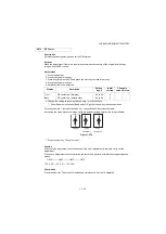
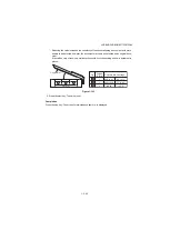
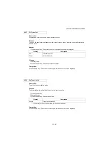
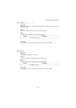
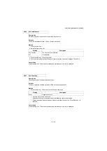
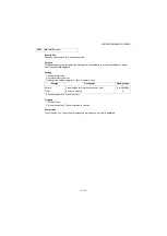
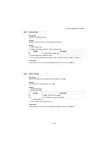
U150
Chk Toner Sensor
Description
Displays the status of each sensor associated with the toner.
Purpose
To check if the sensors operate correctly.
Method
1. Press the start key.
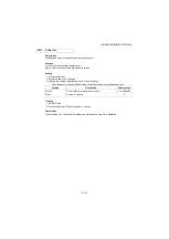
Display
Description
Dev sensor
State of the developer sensor.
2. Check the status of sensor. The current value is displayed.
* : Developer sensor are acquired and re-displayed periodically.
Completion
Press the stop key. The screen for selecting a maintenance item No. is displayed.
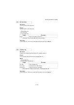
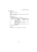
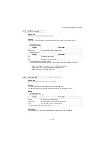
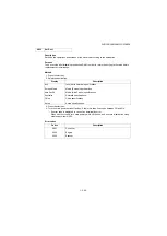
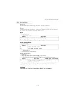
U156
Adj Tnr Ctrl Lv
Description
A toner supply level is adjusted.
Purpose
A toner supply level is adjusted.
Method
1. Press the start key.
2. Select the item to be adjust.
3. Change the value using change keys * or numeric keys.
* : Zoom/Paper selection key (Basic model), Right/Left arrow key (Advanced model)
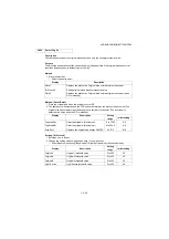
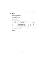
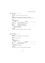
Display
Description
Setting range
Initial
setting
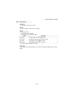
Supply(H)
The maximum threshold value of toner
supply.
0.09 to 2.55
1.30
Supply(L)
The minimum threshold value of toner
supply.
0.09 to 2.55
1.00
SUpply(PH)
The prohibition threshold value of toner
supply.
0.09 to 2.55
1.50
On Time
Time to turn on a toner motor.
50 to 2000
500
Off Time
Time to turn off a toner motor.
50 to 2000
100
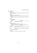
4. Press the start key. The value is set.
Completion
Press the stop key. The screen for selecting a maintenance item No. is displayed.
Summary of Contents for DP-480
Page 6: ...This page is intentionally left blank ...
Page 12: ...This page is intentionally left blank ...
Page 18: ...2NC 2NF 2NG 2NN 3P7 3P8 3P9 This page is intentionally left blank ...
Page 54: ...2NC 2NF 2NG 2NN 3P7 3P8 3P9 1 2 24 This page is intentionally left blank ...
Page 172: ...2NC 2NF 2NG 2NN 3P7 3P8 3P9 1 3 118 This page is intentionally left blank ...
Page 278: ...2NC 2NF 2NG 2NN 3P7 3P8 3P9 2 1 4 106 This page is intentionally left blank ...
Page 434: ...2NC 2NF 2NG 2NN 3P7 3P8 3P9 2 2 44 This page is intentionally left blank ...
Page 446: ...2NC 2NF 2NG 2NN 3P7 3P8 3P9 2 3 12 This page is intentionally left blank ...
Page 455: ...Installation Guide DP 480 Document processor Installation Guide ...
Page 458: ...2 3 4 5 6 A ...
Page 459: ...3 7 8 9 B C C ...
Page 460: ...4 10 ...
Page 473: ...PF 480 300 sheet Paper feeder Installation Guide ...
Page 476: ...2 5 6 4 3 B M3x8 B M3x8 B M3x8 B M3x8 1 2 ...
Page 477: ...3 9 10 8 7 1 2 ...
Page 478: ...4 13 12 11 1 2 C ...
Page 479: ...5 15 14 E D D E D D E D D E D D ...
Page 482: ...DU 480 duplex unit Installation Guide ...
Page 484: ...1 2 3 1 A B M3x8 ...
Page 485: ...2 6 7 5 4 A A B M3x8 ...
Page 489: ...IB 33 Network interface kit Installation Guide ...
Page 490: ...2 3 1 IB 33 2013 7 303PB56710 01 A B ...
Page 491: ...6 7 5 4 2013 7 303PB56710 01 B YC2007 A ...
Page 492: ...FAX System X Installation Guide ...
Page 495: ...2 5 4 3 2 B M3x8 A YC 2003 ...
Page 496: ...3 8 9 7 6 C G G 8 9 7 6 C ...
Page 497: ...4 11 10 12 13 D D E ...
Page 499: ......
Page 500: ......


