


2NC/2NF/2NG/2NN/3P7/3P8/3P9-5
1-3-79
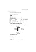
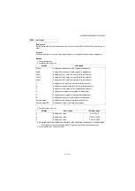
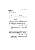
Setting: [Adjust Original]
*:
This setting is usually unnecessary.
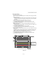
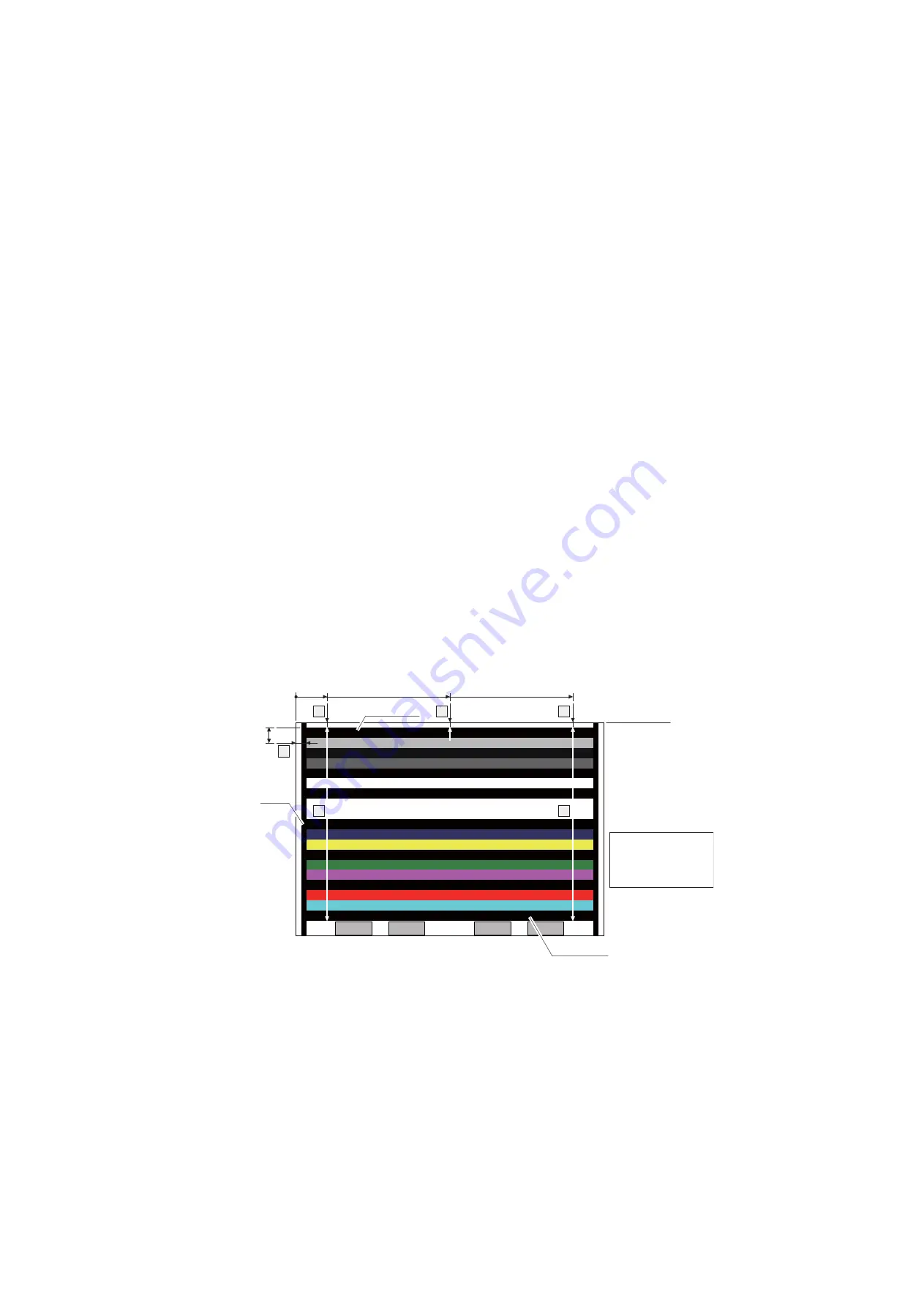
1. Measure the distance from the leading edge to the top of black belt 1 of the original at A, B and
C.
Measurement procedure
1) Measure the distance from the leading edge to the top of black belt 1 of the original at A (30
mm from the left edge), B (148.5 mm from the left edge) and C (267 mm from the left edge),
respectively.
2) Apply the following formula for the values obtained: ((A + B + C) / 3)
2. Enter the values solved using change keys * or numeric keys in [Dist1].
* : Zoom/Paper selection key (Basic model), Right/Left arrow key (Advanced model)
3. Press the start key. The value is set.
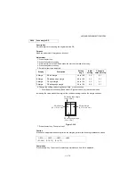
4. Measure the distance from the left edge to the right edge black belt 2 of the original at F.
Measurement procedure
1) Measure the distance from the left edge to the right edge black belt 2 of the original at F (15
mm from the top edge of black belt 1).
5. Enter the values using change keys * or numeric keys in [Dist2].
* : Zoom/Paper selection key (Basic model), Right/Left arrow key (Advanced model)
6. Press the start key. The value is set.
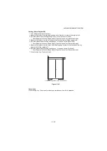
7. Measure the distance from the top edge of black belt 1 to the bottom of black belt 3 of the orig-
inal at D and E.
1) Measure the distance from the top edge of black belt 1 to the bottom of black belt 3 of the
original at D (30 mm from the left edge) and E (267 mm from the left edge), respectively.
2) Apply the following formula for the values obtained: (D/2 + E/2)
8. Enter the measured value using change keys * or numeric keys in [Dist3].
* : Zoom/Paper selection key (Basic model), Right/Left arrow key (Advanced model)
9. Press the start key. The value is set.
Figure 1-3-17
COLOR SCANNER
CHART A4
No.302K357010
Original for adjustment (P/N: 7505000005)
F
A
B
C
D
E
30mm
148.5mm
267mm
15mm
Leading edge
Left edge
[Dist1] = (A+B+C)/3
[Dist2] = F
[Dist3] = D/2+E/2
Black belt 1
Black
belt 2
Black belt 3
Summary of Contents for DP-480
Page 6: ...This page is intentionally left blank ...
Page 12: ...This page is intentionally left blank ...
Page 18: ...2NC 2NF 2NG 2NN 3P7 3P8 3P9 This page is intentionally left blank ...
Page 54: ...2NC 2NF 2NG 2NN 3P7 3P8 3P9 1 2 24 This page is intentionally left blank ...
Page 172: ...2NC 2NF 2NG 2NN 3P7 3P8 3P9 1 3 118 This page is intentionally left blank ...
Page 278: ...2NC 2NF 2NG 2NN 3P7 3P8 3P9 2 1 4 106 This page is intentionally left blank ...
Page 434: ...2NC 2NF 2NG 2NN 3P7 3P8 3P9 2 2 44 This page is intentionally left blank ...
Page 446: ...2NC 2NF 2NG 2NN 3P7 3P8 3P9 2 3 12 This page is intentionally left blank ...
Page 455: ...Installation Guide DP 480 Document processor Installation Guide ...
Page 458: ...2 3 4 5 6 A ...
Page 459: ...3 7 8 9 B C C ...
Page 460: ...4 10 ...
Page 473: ...PF 480 300 sheet Paper feeder Installation Guide ...
Page 476: ...2 5 6 4 3 B M3x8 B M3x8 B M3x8 B M3x8 1 2 ...
Page 477: ...3 9 10 8 7 1 2 ...
Page 478: ...4 13 12 11 1 2 C ...
Page 479: ...5 15 14 E D D E D D E D D E D D ...
Page 482: ...DU 480 duplex unit Installation Guide ...
Page 484: ...1 2 3 1 A B M3x8 ...
Page 485: ...2 6 7 5 4 A A B M3x8 ...
Page 489: ...IB 33 Network interface kit Installation Guide ...
Page 490: ...2 3 1 IB 33 2013 7 303PB56710 01 A B ...
Page 491: ...6 7 5 4 2013 7 303PB56710 01 B YC2007 A ...
Page 492: ...FAX System X Installation Guide ...
Page 495: ...2 5 4 3 2 B M3x8 A YC 2003 ...
Page 496: ...3 8 9 7 6 C G G 8 9 7 6 C ...
Page 497: ...4 11 10 12 13 D D E ...
Page 499: ......
Page 500: ......


