


2NC/2NF/2NG/2NN/3P7/3P8/3P9-6
(1) Connector position.......................................................................................................... 2-2-25
(2) PWB photograph ............................................................................................................ 2-2-25
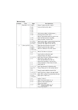
(3) Connector lists................................................................................................................ 2-2-26
(4) Detaching and refitting the PWB. (PSPWB) ................................................................... 2-2-27
(1) Connector position.......................................................................................................... 2-2-29
(2) PWB photograph ............................................................................................................ 2-2-29
(3) Connector lists................................................................................................................ 2-2-30
(4) Detaching and refitting the PWB. (OPPWB)................................................................... 2-2-31
(1) Connector position.......................................................................................................... 2-2-33
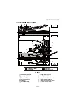
(2) PWB photograph ............................................................................................................ 2-2-33
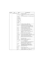
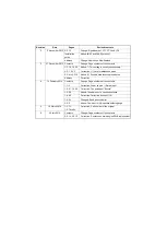
(3) Connector lists................................................................................................................ 2-2-34
(4) Detaching and refitting the PWB. (DPMPWB)................................................................ 2-2-36
(5) Remarks on DP main PWB replacement ....................................................................... 2-2-38
(1) Connector position.......................................................................................................... 2-2-39
(2) PWB photograph ............................................................................................................ 2-2-39
(3) Connector lists................................................................................................................ 2-2-40
(4) Detaching and refitting the PWB. (PFMPWB) ................................................................ 2-2-42
(1-1) Main unit.................................................................................................................. 2-3-1
(1-2) DP-480 .................................................................................................................... 2-3-2
(1-3) PF-480..................................................................................................................... 2-3-2
(1-4) DU-480 .................................................................................................................... 2-3-2
(2) Maintenance kits............................................................................................................... 2-3-3
(3) Periodic maintenance procedures .................................................................................... 2-3-4
(3-1) Main unit.................................................................................................................. 2-3-4
(3-2) DP-480 .................................................................................................................... 2-3-8
(3-3) PF-480................................................................................................................... 2-3-10
(3-4) DU-480 .................................................................................................................. 2-3-10
(4) Repetitive defects gauge ................................................................................................ 2-3-11
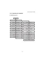
(5) Chart of image adjustment procedures .......................................................................... 2-3-12
(6) Wiring diagram ............................................................................................................... 2-3-15
DP-480 (Document processor)
PF-480 (300-sheet Paper feeder)
DU-480 (duplex unit)
IB-33 (Network interface kit)
FAX System (X)
Summary of Contents for DP-480
Page 6: ...This page is intentionally left blank ...
Page 12: ...This page is intentionally left blank ...
Page 18: ...2NC 2NF 2NG 2NN 3P7 3P8 3P9 This page is intentionally left blank ...
Page 54: ...2NC 2NF 2NG 2NN 3P7 3P8 3P9 1 2 24 This page is intentionally left blank ...
Page 172: ...2NC 2NF 2NG 2NN 3P7 3P8 3P9 1 3 118 This page is intentionally left blank ...
Page 278: ...2NC 2NF 2NG 2NN 3P7 3P8 3P9 2 1 4 106 This page is intentionally left blank ...
Page 434: ...2NC 2NF 2NG 2NN 3P7 3P8 3P9 2 2 44 This page is intentionally left blank ...
Page 446: ...2NC 2NF 2NG 2NN 3P7 3P8 3P9 2 3 12 This page is intentionally left blank ...
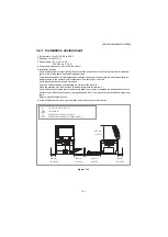
Page 455: ...Installation Guide DP 480 Document processor Installation Guide ...
Page 458: ...2 3 4 5 6 A ...
Page 459: ...3 7 8 9 B C C ...
Page 460: ...4 10 ...
Page 473: ...PF 480 300 sheet Paper feeder Installation Guide ...
Page 476: ...2 5 6 4 3 B M3x8 B M3x8 B M3x8 B M3x8 1 2 ...
Page 477: ...3 9 10 8 7 1 2 ...
Page 478: ...4 13 12 11 1 2 C ...
Page 479: ...5 15 14 E D D E D D E D D E D D ...
Page 482: ...DU 480 duplex unit Installation Guide ...
Page 484: ...1 2 3 1 A B M3x8 ...
Page 485: ...2 6 7 5 4 A A B M3x8 ...
Page 489: ...IB 33 Network interface kit Installation Guide ...
Page 490: ...2 3 1 IB 33 2013 7 303PB56710 01 A B ...
Page 491: ...6 7 5 4 2013 7 303PB56710 01 B YC2007 A ...
Page 492: ...FAX System X Installation Guide ...
Page 495: ...2 5 4 3 2 B M3x8 A YC 2003 ...
Page 496: ...3 8 9 7 6 C G G 8 9 7 6 C ...
Page 497: ...4 11 10 12 13 D D E ...
Page 499: ......
Page 500: ......