


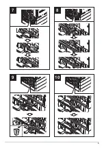

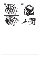
12
a
k
j
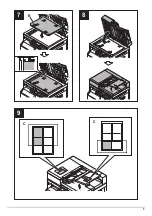
1
2
2.0mm
2
2.0mm
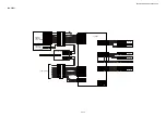
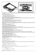
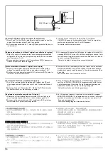
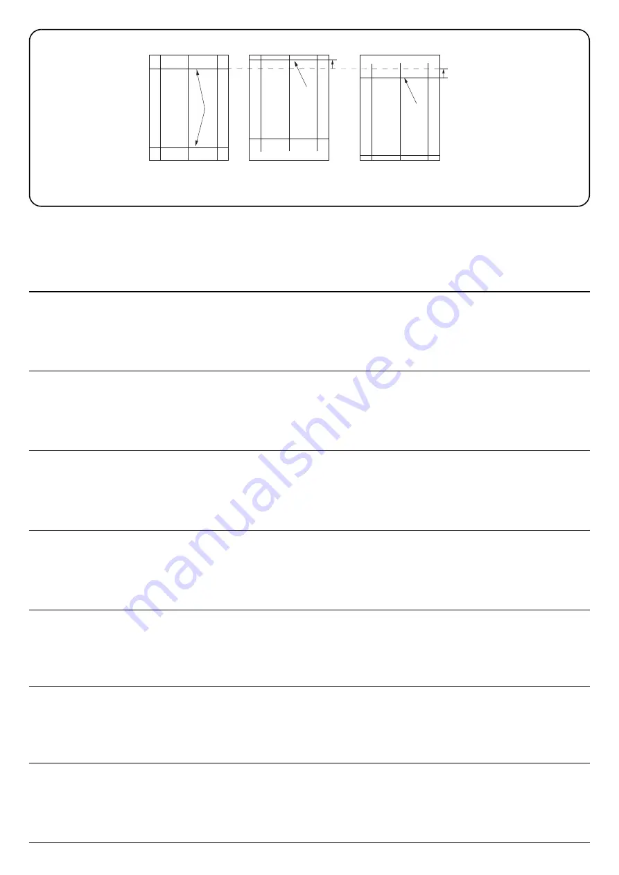
[Checking the leading edge timing]
1.
Check the gap between line (1) on original (a) and line (2) of copy
example.If there is the gap, adjust the gap according to the following
procedure.
<Reference value>
Vertical gap of line (2): within ±2.0 mm
2.
Use the maintenance mode U071 to adjust the timing.
Front Head: Adjusts the leading edge timing (surface)
Back Head: Adjusts the leading edge timing (rear side)
[Vérification de la synchronisation du bord avant]
1.
Vérifier l’écart entre la ligne (1) de l’original (a) et la ligne (2) de l’exem-
ple de copie. S’il existe un écart, le régler selon la procédure suivante.
<Valeur de référence>
Écart vertical de la ligne (2) : ±2,0 mm
2.
Pour régler la synchronisation, utilisez le mode entretien U071.
Front Head: Permet de régler la synchronisation du bord de tête (surface)
Back Head: Permet de régler la synchronisation du bord de tête
(arrière)
[Cambio de la sincronización de borde superior]
1.
Compruebe la separación entre la línea (1) del original (a) y la línea (2)
del ejemplo de copia. Si queda una separación, ajústela siguiendo el
siguiente procedimiento.
<Valor de referencia>
Separación vertical de la línea (2): dentro de ±2,0 mm
2.
Para ajustar la sincronización utilice el modo de mantenimiento U071.
Front Head: Ajusta la sincronización del borde superior (anverso).
Back Head: Ajusta la sincronización del borde superior (reverso).
[Überprüfen des Vorderkanten-Timings]
1.
Den Abstand zwischen der Linie (1) des Originals (a) und der Linie (2)
des Kopierbeispiels prüfen. Falls ein Abstand zu sehen ist, justieren
Sie diesen durch die folgende Vorgehensweise.
<Bezugswert>
Vertikaler Abstand der Linie (2): Innerhalb ±2,0 mm
2.
Zum Einstellen des Timing den Wartungsmodus U071 verwenden.
Front Head: Zur Einstellung des Vorderkanten-Timing (Oberfläche)
Back Head: Zur Einstellung des Vorderkanten-Timing (Rückseite)
[Controllo della sincronizzazione del bordo principale]
1.
Verificare lo scostamento fra la linea (1) sull’originale (a) e la linea (2)
dell’esempio di copia. Se vi è uno scostamento, regolarlo attenendosi
alla seguente procedura.
<Valore di riferimento>
Scostamento verticale della linea (2) compreso fra ±2,0 mm
2.
Usare la modalità di manutenzione U071 per regolare la
sincronizzazione.
Front Head: Regola la sincronizzazione del bordo principale (superficie)
Back Head: Regola la sincronizzazione del bordo principale (lato posteri-
ore)
[ 先端タイミング確認 ]
1.
原稿 (a) の線 (1) とコピーサンプルの線 (2) のずれを確認する。ずれ
がある場合、
次の手順で調整を行う。
<基準値>
線 (2) の上下ずれ:±2.0mm 以内
2.
メンテナンスモード U071 をセットし、
調整を行う。
Front Head :先端タイミング ( 表面 ) を調整する
Back Head: 先端タイミング ( 裏面 ) を調整する
[ 确认前端定时调整 ]
1.
确认原稿(a)上的线(1)和复印样本上的线(2)之间的偏移值。如有偏
移,请按下面的步骤来调整。
< 标准值 >
线(2)的上下偏移值 :±2.0mm 以内
2.
使用维修模式 U071 调整定时。
Front Head :调整前端对位 ( 正面 )
Back Head :调整前端对位 ( 反面 )
[ 선단 타이밍확인 ]
1.
원고 (a) 선 (1) 과 벨크로 선 (2) 의 차이를 확인합니다 . 차이가 있는 경
우 , 다음 과정을 통하여 차이를 조정합니다 .
<기준치>
선 (2) 의 상하차이:±2.0mm 이내
2.
메인터넌스 모드 U071 을 세트하고 조정을 합니다 .
Front Head :선단 타이밍 ( 표면 ) 을 조정합니다 .
Back Head :선단 타이밍 ( 뒷면 ) 을 조정합니다 .
Summary of Contents for DP-480
Page 6: ...This page is intentionally left blank ...
Page 12: ...This page is intentionally left blank ...
Page 18: ...2NC 2NF 2NG 2NN 3P7 3P8 3P9 This page is intentionally left blank ...
Page 54: ...2NC 2NF 2NG 2NN 3P7 3P8 3P9 1 2 24 This page is intentionally left blank ...
Page 172: ...2NC 2NF 2NG 2NN 3P7 3P8 3P9 1 3 118 This page is intentionally left blank ...
Page 278: ...2NC 2NF 2NG 2NN 3P7 3P8 3P9 2 1 4 106 This page is intentionally left blank ...
Page 434: ...2NC 2NF 2NG 2NN 3P7 3P8 3P9 2 2 44 This page is intentionally left blank ...
Page 446: ...2NC 2NF 2NG 2NN 3P7 3P8 3P9 2 3 12 This page is intentionally left blank ...
Page 455: ...Installation Guide DP 480 Document processor Installation Guide ...
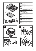
Page 458: ...2 3 4 5 6 A ...
Page 459: ...3 7 8 9 B C C ...
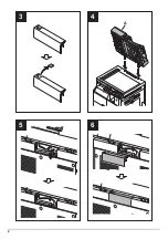
Page 460: ...4 10 ...
Page 473: ...PF 480 300 sheet Paper feeder Installation Guide ...
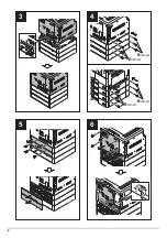
Page 476: ...2 5 6 4 3 B M3x8 B M3x8 B M3x8 B M3x8 1 2 ...
Page 477: ...3 9 10 8 7 1 2 ...
Page 478: ...4 13 12 11 1 2 C ...
Page 479: ...5 15 14 E D D E D D E D D E D D ...
Page 482: ...DU 480 duplex unit Installation Guide ...
Page 484: ...1 2 3 1 A B M3x8 ...
Page 485: ...2 6 7 5 4 A A B M3x8 ...
Page 489: ...IB 33 Network interface kit Installation Guide ...
Page 490: ...2 3 1 IB 33 2013 7 303PB56710 01 A B ...
Page 491: ...6 7 5 4 2013 7 303PB56710 01 B YC2007 A ...
Page 492: ...FAX System X Installation Guide ...
Page 495: ...2 5 4 3 2 B M3x8 A YC 2003 ...
Page 496: ...3 8 9 7 6 C G G 8 9 7 6 C ...
Page 497: ...4 11 10 12 13 D D E ...
Page 499: ......
Page 500: ......


