


2NC/2NF/2NG/2NN/3P7/3P8/3P9-1
2-2-26
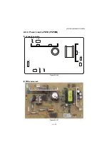
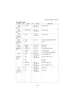
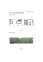
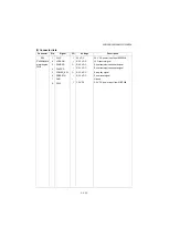
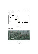
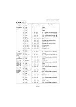
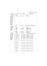
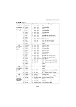
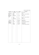
(3) Connector lists
Connector
Pin
Signal
I/O
Voltage
Description
TB1
1
AC LIVE
I
120 V AC
220-240 V AC
AC power input
Connect to
inlet
TB2
1
AC NEUTRAL
I
120 V AC
220-240 V AC
AC power input
Connect to
inlet
TB5
1
HCOM
I
120 V AC
220-240 V AC
AC power input
Connect to
fuse themo-
stat
CN1
1
+24V0
O
24 V DC
24 V DC power output to M/EPWB
Connect to
main/engine
PWB
2
GND
-
-
Ground
CN2
1
MHREM
I
0/3.3 V DC
MH: On/Off
Connect to
main/engine
PWB
2
SHREM
I
0/3.3 V DC
SH: On/Off
3
RELAYREM
I
0/3.3 V DC
Power relay signal: On/Off
4
ZCROSS
I
0/3.3 V DC
Zero-cross signal
5
+24VIL
I
24 V DC
24 V DC power output to M/EPWB
CN3
1
LIVE
O
120 V AC
220-240 V AC
AC power output to CH
Connect to
cassette
heater
2
LIVE
O
120 V AC
220-240 V AC
AC power output to PFCH
3
NC
-
-
Not used
4
NC
-
-
Not used
5
NEUTRAL
O
120 V AC
220-240 V AC
AC power output to CH
6
NEUTRAL
O
120 V AC
220-240 V AC
AC power output to PFCH
CN4
1
MH
O
120 V AC
220-240 V AC
MH: On/Off
Connect to
fuse heater1,
2
2
SH
O
120 V AC
220-240 V AC
SH: On/Off
Summary of Contents for DP-480
Page 6: ...This page is intentionally left blank ...
Page 12: ...This page is intentionally left blank ...
Page 18: ...2NC 2NF 2NG 2NN 3P7 3P8 3P9 This page is intentionally left blank ...
Page 54: ...2NC 2NF 2NG 2NN 3P7 3P8 3P9 1 2 24 This page is intentionally left blank ...
Page 172: ...2NC 2NF 2NG 2NN 3P7 3P8 3P9 1 3 118 This page is intentionally left blank ...
Page 278: ...2NC 2NF 2NG 2NN 3P7 3P8 3P9 2 1 4 106 This page is intentionally left blank ...
Page 434: ...2NC 2NF 2NG 2NN 3P7 3P8 3P9 2 2 44 This page is intentionally left blank ...
Page 446: ...2NC 2NF 2NG 2NN 3P7 3P8 3P9 2 3 12 This page is intentionally left blank ...
Page 455: ...Installation Guide DP 480 Document processor Installation Guide ...
Page 458: ...2 3 4 5 6 A ...
Page 459: ...3 7 8 9 B C C ...
Page 460: ...4 10 ...
Page 473: ...PF 480 300 sheet Paper feeder Installation Guide ...
Page 476: ...2 5 6 4 3 B M3x8 B M3x8 B M3x8 B M3x8 1 2 ...
Page 477: ...3 9 10 8 7 1 2 ...
Page 478: ...4 13 12 11 1 2 C ...
Page 479: ...5 15 14 E D D E D D E D D E D D ...
Page 482: ...DU 480 duplex unit Installation Guide ...
Page 484: ...1 2 3 1 A B M3x8 ...
Page 485: ...2 6 7 5 4 A A B M3x8 ...
Page 489: ...IB 33 Network interface kit Installation Guide ...
Page 490: ...2 3 1 IB 33 2013 7 303PB56710 01 A B ...
Page 491: ...6 7 5 4 2013 7 303PB56710 01 B YC2007 A ...
Page 492: ...FAX System X Installation Guide ...
Page 495: ...2 5 4 3 2 B M3x8 A YC 2003 ...
Page 496: ...3 8 9 7 6 C G G 8 9 7 6 C ...
Page 497: ...4 11 10 12 13 D D E ...
Page 499: ......
Page 500: ......


