


2NC/2NF/2NG/2NN/3P7/3P8/3P9-2
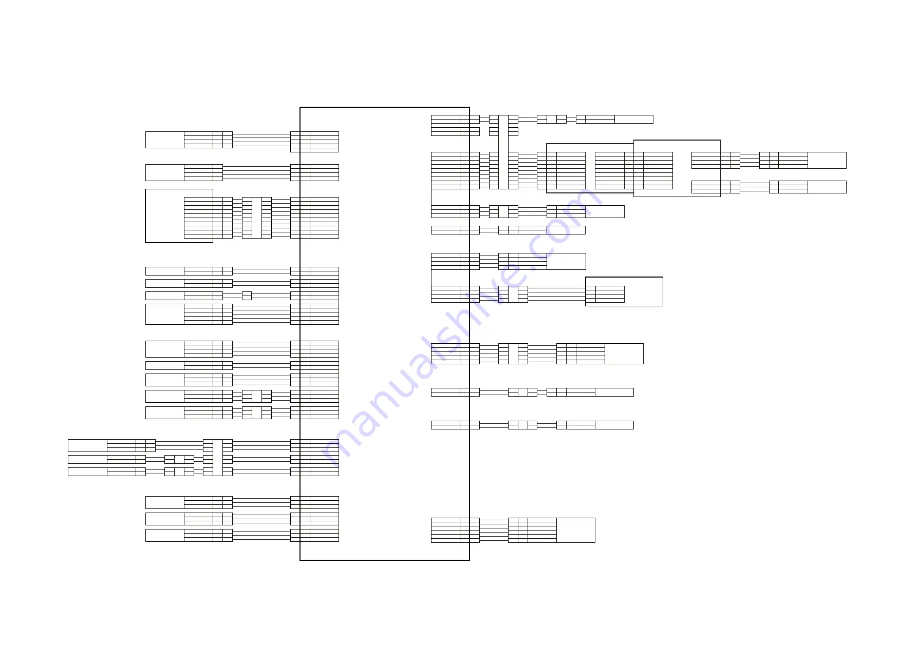
2-3-15
(6) Wiring diagram
No.1
CL
TEMS
SPWB
YC1
YC2
+5VZD
TON_EMP
YC1
YC3
GND
YC10
YC4
YC12
YC11
YC5
YC6
YC7
YC13
YC8
YC19
CONTRPWB
+24V4
FAN_REM
4
9
10
+24V4
8
8
DBDCCNT
7
6
7
8
5
10
11
12
5
8
7
6
MCNT
1
3
GND
TC_DATA
TC_CLK
3.3V3
ERASE3
GND
ERASE3
ERASE2
2
3
2
3
GND
3
4
MAIN
_
READY
MAIN
_
CLK
MM
2
3
2
2
NC
1
1
1
PAPLSIZE3
2
PAPLSIZE2
GND
13
1
13
8
3
1
2
3
1
2
DRUM_SCL
DRUM_SCL
2
1
DRUM_SDA
8
3.3V4
DRUM_SCL
2
8
GND
1
3
2
3
1
1
2
1
2
3
3
PS
3.3V4LED
3
3
GND
PAPEMP
1
7
+3.3V4
3.3V4
1
1
6
6
SCA_COVER
SCA_SIZE
8
GND
8
+3.3V4LED
6
6
GND
1
2
2
7
7
DRUM_SCL
DRUM_SDA
3
TM
2
2
LMOT_REM
1
1
+24V4
1
LMOT_REM
2
2
15
3
3
2
2
1
2
2
6
7
TH2
PWSW
PAPLSIZE3
PAPLSIZE2
2
MPSOL
+24V4
1
MPF_SOL_REM
1
2
1
1
SCANNER_B-
2
2
SCANNER_B
SCANNER_A
4
1
SCANNER_A-
ISUM
3
SCANNER_B-
4
4
SCANNER_B
GND
SREM
PLSW
10
1
1
2
1
1
GND
PAPWSIZE1
1
SISEL
2
2
2
SCANNER_A
SCANNER_A-
2
2
1
1
3
3
4
4
3
3
5
5
4
4
3
1
1
DU B-
2
DU B
2
2
TEM_DATA
1
1
+3.3V0
4
4
HUM_CLK2
3
3
HUM_CLK1
6
6
GND
5
5
HUM_DATA
TEM_DATA
5
5
+3.3V0
6
6
HUM_CLK2
3
3
HUM_CLK1
4
4
GND
1
1
HUM_DATA
2
2
3.3V3
1
1
1
SUB_DATA
3
3
GND
2
2
8
8
GND
6
TC_CLK
7
7
TC_DATA
6
4
SUB_CLK
4
4
4
+3.3V3
5
5
+3.3V3
SUB_CLK
2
SUB_DATA
3
3
GND
SISEL
9
5
7
4
4
3
2
3
4
6
6
TCNT
5
2
3
2
2
GND
3.3V4LED
3
2
OSS
GND
SCA_SIZE
HPS
3.3V4
ODSW
3.3V4
GND
SCA_COVER
SCA_HP
2
4
4
2
7
7
1
1
9
9
MPPS
3.3V2LED
GND
MPF
_
EMPTY
+3.3V4LED
5
3
3
SCA_HP
5
GND
GND
MAIN
_
READY
5
5
MAIN
_
CLK
4
4
RS
MAIN
_
REM
RESIST
3
2
3
2
7
1
3
4
5
4
7
4
1
TH1
5
5
GND
8
3
4
4
3
3
2
2
2
1
1
PAPLSIZE1
1
1
11
9
14
1
3
11
10
10
8
GND
9
MPF
_
EMPTY
2
7
+3.3V3LED
3
4
6
6
GND
7
9
MAIN
_
REM
10
5
3
GND
4
PAPLSIZE1
11
11
1
1
+24V4
3
3
3
1
2
1
1
+24V4
3
3
1
1
8
DBCLK
2
2
4
4
DBDCCNT
TREM
+3.3V4
10
+24VIL
DU A
1
FCOVER
7
DU A-
3
5
5
6
6
3
2
2
7
8
9
GND
+24VIL
1
1
10
3
3
REG_CL_REM
4
4
+24V4
2
2
+24V4
12
12
PAPEMP
+24VIL
5
PAPWSIZE1
1
FEED_CL_REM
6
6
5
5
9
9
1
10
10
9
10
3
2
1
GND
14
GND
+3.3V4LED
+3.3V4LED
13
15
RESIST
1
2
1
1
1
4
TON_EMP
4
1
3.3VLED
WTS
DRUM_SDA
3
3
6
6
DRUM_SDA
3.3V4
3.3V4
WT_LED
2
2
2
2
WT_LED
GND
4
4
5
5
GND
GND
3
GND
WT_SENS
3
3
3
3
WT_SENS
4
DURM_TEMP
5
5
9
3.3V4
5
4
4
4
3.3V4
ERASE2
6
6
4
10
4
WT_SENS
4
ERASE2
ERASE3
3
7
7
3
11
3
8
2
12
2
1
2
13
12
1
ERASE2
5
9
6
7
7
6
ERASE3
ERASE2
WT_LED
9
9
1
6
5
1
2
WT_SENS
WT_LED
2
7
8
WT_LED
WT_LED
3
4
2
3
2
1
1
2
ERASE2
1
1
1
PM
1
FUSER
_
JAM
GND
+24V4
MPF_SOL_REM
GND
7
8
3
+3.3V4LED
1
1
5
1
2
1
1
CLK
+24V4
5
4
3
2
3
REM
2
5
1
2
3
RDY
24V4
5
4
PGND
GND
5VZD
1
2
3
4
10
11
12
3
4
5
4
3
2
1
2
3
B3
2
3
SREM
MISENS
MCNT
TCNT
3
1
+24VIL
3
5
3
2
1
B1
A3
A1
1
GND
2
DUM
PFCL
FEED_CL_REM
2
RCL
REG_CL_REM
GND
1
FUES
FTH1
2
TH1
GND
1
FUSER
_
JAM
3
3.3V4
1
1
FRCSW
2
2
GND
FCOVER
1
1
6
4
1
2
2
2
3
TREM
MISENS
DBCLK
POL_RDY
4
9
8
8
7
3.3VLED
ERASE3
WT_SENS
ERASE3
5
8
7
6
FTH2
TH2
2
GND
1
1
2
2
1
2
1
1
2
POWER_SW
GND
1
2
2
1
1
2
TS
EFM
1
2
2
1
2
FAN_REM
1
2
+24V4
POWERSW
1
1
GND
2
2
WT_SENS
8
3
GND
1
POL_CLK
5
1
GND
2
POL_REM
1
1
3
2
2
2
2
1
MEPWB
HVPWB
DRPWB
PSSW
3
4
11
10
SCOVERF
3
3
GND
4
4
DRRPWB
YC9
YC20
Summary of Contents for DP-480
Page 6: ...This page is intentionally left blank ...
Page 12: ...This page is intentionally left blank ...
Page 18: ...2NC 2NF 2NG 2NN 3P7 3P8 3P9 This page is intentionally left blank ...
Page 54: ...2NC 2NF 2NG 2NN 3P7 3P8 3P9 1 2 24 This page is intentionally left blank ...
Page 172: ...2NC 2NF 2NG 2NN 3P7 3P8 3P9 1 3 118 This page is intentionally left blank ...
Page 278: ...2NC 2NF 2NG 2NN 3P7 3P8 3P9 2 1 4 106 This page is intentionally left blank ...
Page 434: ...2NC 2NF 2NG 2NN 3P7 3P8 3P9 2 2 44 This page is intentionally left blank ...
Page 446: ...2NC 2NF 2NG 2NN 3P7 3P8 3P9 2 3 12 This page is intentionally left blank ...
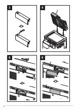
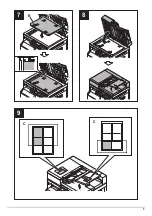
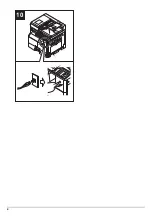
Page 455: ...Installation Guide DP 480 Document processor Installation Guide ...
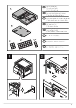
Page 458: ...2 3 4 5 6 A ...
Page 459: ...3 7 8 9 B C C ...
Page 460: ...4 10 ...
Page 473: ...PF 480 300 sheet Paper feeder Installation Guide ...
Page 476: ...2 5 6 4 3 B M3x8 B M3x8 B M3x8 B M3x8 1 2 ...
Page 477: ...3 9 10 8 7 1 2 ...
Page 478: ...4 13 12 11 1 2 C ...
Page 479: ...5 15 14 E D D E D D E D D E D D ...
Page 482: ...DU 480 duplex unit Installation Guide ...
Page 484: ...1 2 3 1 A B M3x8 ...
Page 485: ...2 6 7 5 4 A A B M3x8 ...
Page 489: ...IB 33 Network interface kit Installation Guide ...
Page 490: ...2 3 1 IB 33 2013 7 303PB56710 01 A B ...
Page 491: ...6 7 5 4 2013 7 303PB56710 01 B YC2007 A ...
Page 492: ...FAX System X Installation Guide ...
Page 495: ...2 5 4 3 2 B M3x8 A YC 2003 ...
Page 496: ...3 8 9 7 6 C G G 8 9 7 6 C ...
Page 497: ...4 11 10 12 13 D D E ...
Page 499: ......
Page 500: ......


