2H4
2-3-3
2-3-2 Control PWB
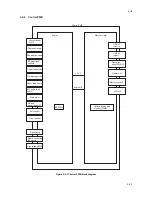
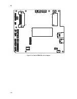
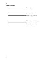
Figure 2-3-3 Control PWB block diagram
Control PWB
Engine
Main controller
EEPROM
+3.3 V
Laser scanner
unit I/F
Optional expanded
memory (DIMM)
Engine I/F
Duplex solenoid
Developing clutch
MP paper feed
solenoid
Registration clutch
Paper feed clutch
Paper feed sensor
MP paper feed
sensor
Main motor
Exit sensor
Toner sensor
High voltage PWB
Right/Left cooling
fan motors
Eraser lamp
Optional
paper feeder I/F
Network I/F
USB I/F
(Device)
USB I/F
(Host)
Operation
panel PWB I/F
Memory card I/F
KUIO I/F
Summary of Contents for ECOSYS FS-1350DN
Page 1: ...SERVICE MANUAL Published in October 2008 842H4010 2H4SM060 First Edition FS 1350DN ...
Page 3: ...Revision history Revision Date Replaced pages Remarks ...
Page 4: ...This page is intentionally left blank ...
Page 10: ...This page is intentionally left blank ...
Page 18: ...2H4 1 1 6 This page is intentionally left blank ...
Page 21: ...2H4 1 2 3 1 Removing the tapes Procedure 1 Remove three tapes Figure 1 2 3 Tape Tape Tape ...
Page 24: ...2H4 1 2 6 This page is intentionally left blank ...
Page 57: ...2H4 1 5 5 5 Unhook seven hooks and then remove the left cover Figure 1 5 6 Left cover Hooks ...
Page 106: ...2H4 2 1 16 This page is intentionally left blank ...
Page 110: ...2H4 2 2 4 This page is intentionally left blank ...
Page 118: ...2H4 2 3 8 This page is intentionally left blank ...
Page 121: ......
Page 122: ......

