5JR
1-3-10
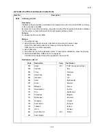
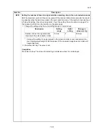
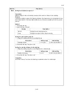
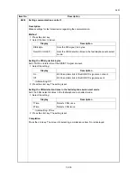
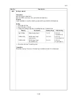
U612
Setting system 3
Description
Makes settings for fax transmission regarding operation and automatic printing of the protocol
list.
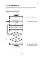
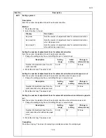
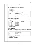
Method
1. Press the start key.
2. Select the item to be set using the cursor up/down keys.
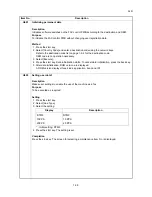
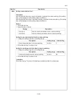
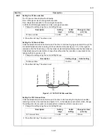
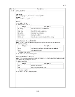
Selecting if auto reduction in the auxiliary direction is to be performed
Sets whether to receive a long document by automatically reducing it in the auxiliary direction or
at 100% magnification.
1. Select the setting using the cursor left/right keys.
* : Initial setting: On
2. Press the start key. The setting is set.
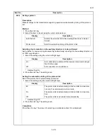
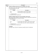
Setting the automatic printing of the protocol list
Sets if the protocol list is automatically printed out.
1. Select the setting using the cursor left/right keys.
* : Initial setting: Off
2. Press the start key. The setting is set.
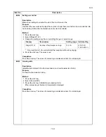
Completion
Press the stop key. The screen for selecting a maintenance item No. is displayed.
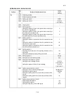
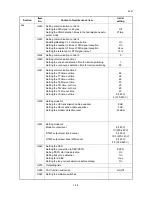
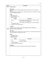
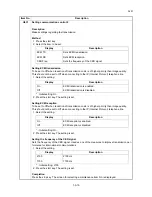
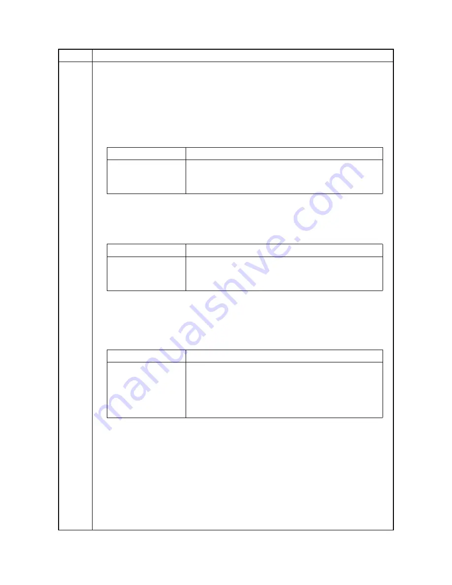
Item No.
Description
Display
Description
Auto Reduct
Selects if auto reduction in the auxiliary direction is to be per-
formed.
Protocol List
Sets the automatic printing of the protocol list.
Display
Description
On
Auto reduction is performed if the received document is longer
than the fax paper.
Off
Auto reduction is not performed.
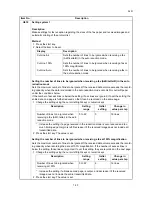
Display
Description
Err
The protocol list is automatically printed out after communica-
tion only if a communication error occurs.
On
The protocol list is automatically printed out after communica-
tion.
Off
The protocol list is not printed out automatically.
Summary of Contents for Fax System (U)
Page 1: ...SERVICE MANUAL Published in October 2010 845JR110 5JRSM060 First Edition FAX System U ...
Page 3: ...Revision history Revision Date Replaced pages Remarks ...
Page 4: ...This page is intentionally left blank ...
Page 10: ...This page is intentionally left blank ...
Page 12: ...5JR This page is intentionally left blank ...
Page 22: ...5JR 1 2 4 This page is intentionally left blank ...
Page 60: ...5JR 1 4 8 This page is intentionally left blank ...
Page 62: ...5JR 1 5 2 This page is intentionally left blank ...
Page 64: ...5JR 1 6 2 This page is intentionally left blank ...
Page 66: ...5JR 2 1 2 This page is intentionally left blank ...
Page 68: ...5JR 2 2 2 This page is intentionally left blank ...
Page 69: ......
Page 70: ......


