3KH-2
1-2-7
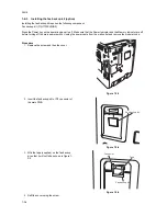
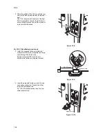
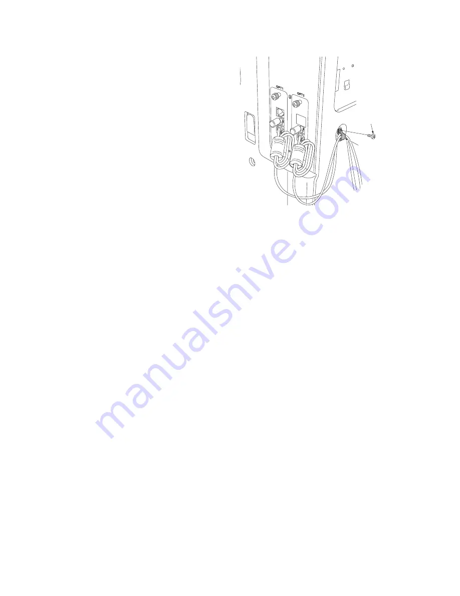
6. Connect the modular cord that have been
removed before installing the dual FAX.
7. Remove the screw from the rear cover.
8. Attach the clamp to the two modular cords
and secure it with the screw that have been
removed in step 7.
Figure 1-2-11
9. Connect the power cord and turn the main
power switch on.
10. Enter maintenance mode, run U698 and set
the target port for maintenance mode to [P2]
(see P.1-3-25).
11. Run the maintenance item U600 to initialize
the fax control PWB of the dual FAX (see
P.1-3-5).
Caution
Selecting [ALL] using U698 initializes the FAX control PWB.
If the FAX system is already in use and the dual FAX is being additionally installed, be sure to select [P2] using U698 and
run U600.
For 120 V specifications only
12. Set the telephone line (see P.1-3-31).
13. Register the local FAX number (see P.1-3-
31).
Clamp
Screw
Summary of Contents for FaxSystem(M)
Page 1: ...SERVICE MANUAL Published in March 2007 843KH113 3KHSM063 Rev 3 FaxSystem M...
Page 4: ...This page is intentionally left blank...
Page 10: ...This page is intentionally left blank...
Page 12: ...3KH 2 2 2 Operation of the PWBs 2 2 1 Fax control PWB 2 2 1 2 2 2 NCU PWB 2 2 5...
Page 26: ...3KH 2 1 2 8 This page is intentionally left blank...
Page 76: ...3KH 1 5 2 This page is intentionally left blank...
Page 78: ...3KH 1 6 2 This page is intentionally left blank...
Page 80: ...3KH 2 1 2 This page is intentionally left blank...
Page 87: ......
Page 88: ......

