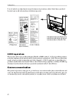
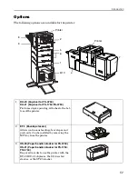
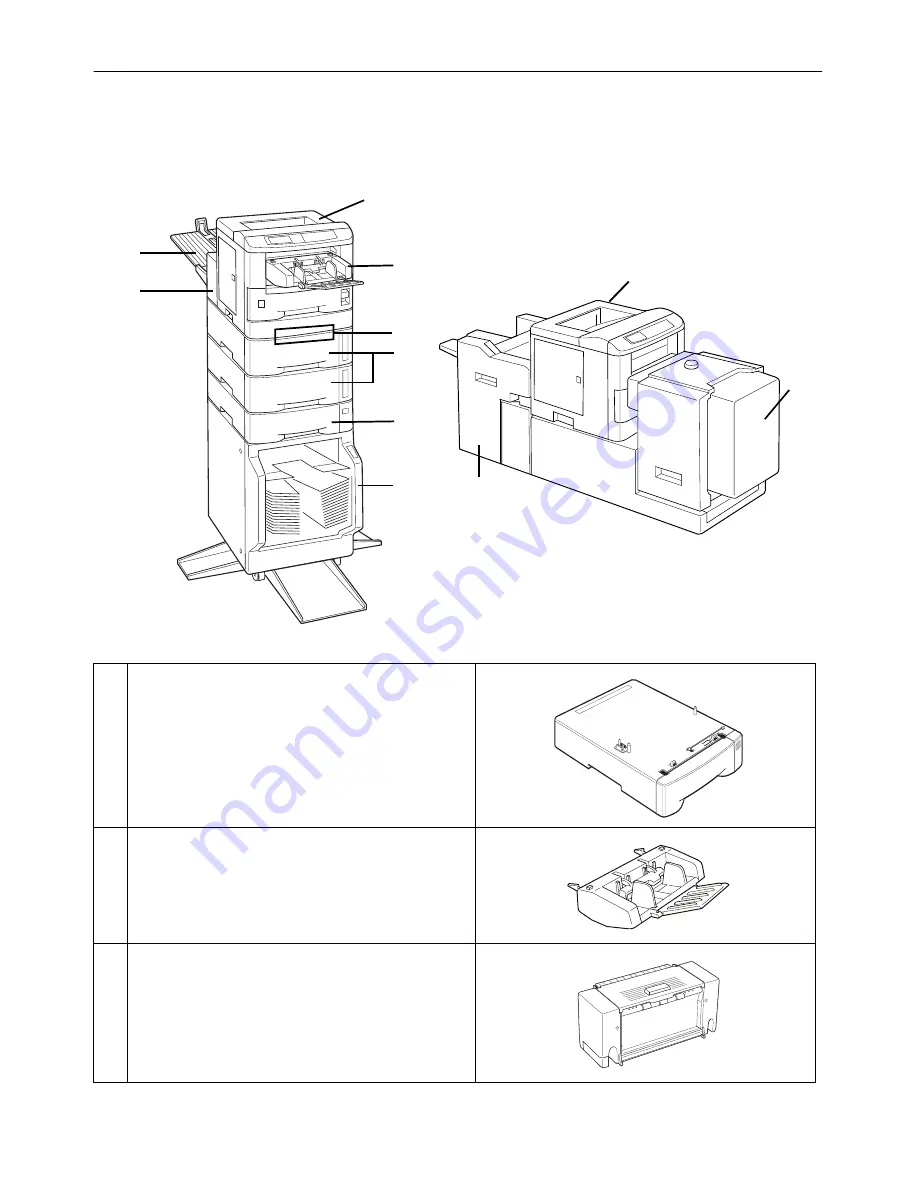
background image

Introduction

xv

Options

The following options are available for the printer.

1

DU-20 (Duplexer for FS-3750)
DU-21 (Duplexer for FS-1750/FS-3750)

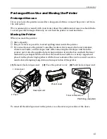
Performs duplex printing. Attaches to the bot-
tom of the printer.

2

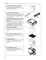
EF-1 (Envelope feeder)

Allows continuous feeding of envelopes and 
postcards. Can be installed by removing the 
MP tray from the printer.

3

HS-20 (Paper handler/stacker for FS-3750)
HS-21 (Paper handler/stacker for FS-1750/
FS-3750)

Required in order to use the printer with the 
DU-20/DU-21 duplexer, the SO-6 sorter/
stacker, or the ST-20 stacker.

5

1

6

8

3

Printer

2

9/10

7

Printer

4

Summary of Contents for FS-3750 - B/W Laser Printer

Page 1: ...FS 1750 FS 3750 ...

Page 2: ...ntain the same copyright notice as the material from which the copying is done Regarding Tradenames PRESCRIBE is a registered trademark of Kyocera Corporation PRESCRIBE 2e KPDL and KIR Kyocera Image Refinement are trademarks of Kyocera Corporation Diablo 630 is a product of Xerox Corporation IBM Proprinter X24E is a product of International Business Machines Corporation Epson LQ 850 is a product o...

Page 3: ...Y AND FITNESS FOR A PARTICULAR PURPOSE Some jurisdictions do not allow the exclusion of implied warranties so the above exclusion may not apply to you SUPPLEMENT TO AGREEMENT FOR SOFTWARE BUNDLING AND DISTRIBUTION FOR ALDC 3 Limitation of Remedies IBM s entire liability under this license is the following 1 For any claim including fundamental breach in any form related in any way to this license I...

Page 4: ...h failure is not remedied within thirty 30 days after notice from Agfa Japan When this License expires or is termi nated you shall either return to Agfa Japan or destroy all copies of the Software and Typefaces and documen tation as requested 6 You agree that you will not modify alter disassemble decrypt reverse engineer or decompile the Software 7 AgfaJapanwarrantsthatforninety 90 daysafterdelive...

Page 5: ...ption which can be determined by turning the equipment off and on the user is encouraged to try to correct the interference by one or more of the following measures Reorient or relocate the receiving antenna Increase the separation between the equipment and receiver Connect the equipment into an outlet on a circuit different from that to which the receiver is connected Consult the dealer or an exp...

Page 6: ...ing the protective cap supplied Use shielded interface cable Safety information Laser safety This printer is certified as a Class 1 laser product under the U S Department of Health and Human Services DHHS Radiation Performance Standard according to Radiation Control for Health and Safety Act of 1968 This means that the printer does not produce hazardous laser radiation Since radiation emitted insi...

Page 7: ...andatory for products marketed in the United States A label indicating compliance with the CDRH reg ulations must be attached to laser products marketed in the United States Ozone concentration The printers generate ozone gas O3 which may concentrate in the place of installation and cause an unpleasant smell To minimize concentration of ozone gas to less than 0 1 ppm we recommend you not to instal...

Page 8: ...rd Do not locate this product where per sons will walk on the cord 8 If an extension cord is used with this product make sure that the total of the ampere ratings on the products plugged into the extension cord do not exceed the extension cord ampere rating 9 Never push objects of any kind into this product through cabinet slots as they may touch dangerous voltage points or short out parts that co...

Page 9: ...nditions 1 This device may not cause harmful interference and 2 this device must accept any interference received including interference that may cause undesired operation CE Marking Directive according to Council Directive 89 336 EEC and 73 23 EEC Manufacturer s name Kyocera Corporation Printer Division Manufacturer s address 2 14 9Tamagawadai SetagayaWard Tokyo158 8610 Japan declares that the pr...

Page 10: ...ement optional units EF 1 PF 21 DU 21 HS 21 and ST 20 etc Description of device This Page Printer Model FS 3750 is the 18ppm FS 1750 is the 14ppm A4 size and utilized plane paper laser dry toner etc The printer can be equipped with several enhancement optional units as a paper feeder as PF 21 a duplexer as DU 21 a sorter as ST 20 etc Conforms to the following product specifications AS NZS 3548 199...

Page 11: ...ada Cet appareil numérique de la classe B est conforme à la norme NMB 003 du Canada ISO 7779 Maschinenlärminformationsverordnung 3 GSGV 18 01 1991 Der höchste Schalldruck pegel beträgt 70 dB A oder weniger gemäß ISO 7779 Disclaimer We shall have no liability or responsibility to customers or any other person or entity with respect to any liability loss or damage caused or alleged to be caused dire...

Page 12: ...other location first remove the toner container waste toner bottle and developer unit After removing the developer unit from the printer put it into the supplied plastic bag and place it into the box in which the toner container is packaged Make sure that the waste toner bottle is securely capped and place it in the plastic bag together with the toner container Be sure to consult a service man bef...

Page 13: ...eriods of time For details on the sleep timer function and printer power consumption refer to the instruc tion manual provided with the printer Initial settings of the sleep timer function and power saved using the sleep timer function ENERGY STAR program guideline The action program Energy 2000 Energy partnership for a sustainable development We get further with all our energy Kyocera ECO PRODUCT...

Page 14: ...uality Using 1200 dots per inch in Fast 1200 mode or Fine 1200 mode the printout is close to typeset quality Also with Kyocera Image Refinement KIR technology high quality printing can be achieved even at 600 dpi and 300 dpi High speed A4 sizes typically print at the rate of 18 14 for the FS 1750 pages per minute Actual time varies according to page complexity Large paper capacity Approximately 25...

Page 15: ...t PCL 6 symbol sets Display of printer messages in any of four languages English French German or Italian As an option it is also possible to download the mes sages in other languages Please contact your Kyocera dealer Memory card slot for option fonts macros forms etc Data in the memory card can be selectively read from the printers control panel Simple network management protocol SNMP compliance...

Page 16: ...m of the printer 2 EF 1 Envelope feeder Allows continuous feeding of envelopes and postcards Can be installed by removing the MP tray from the printer 3 HS 20 Paper handler stacker for FS 3750 HS 21 Paper handler stacker for FS 1750 FS 3750 Required in order to use the printer with the DU 20 DU 21 duplexer the SO 6 sorter stacker or the ST 20 stacker 5 1 6 8 3 Printer 2 9 10 7 Printer 4 ...

Page 17: ...f paper Up to two paper feeders can be attached to the bot tom of the printer unit However the PF 20mini PF 21mini cannot be used together with options such as duplexers or sorters 7 PF 7E Bulk paper feeder Holdsuptoabout2 000sheetsofpaper Canbe installed by removing the MP tray from the printer 8 PT 4 Face up output tray for FS 1750 This is a face up output tray It attaches to the rear of the pri...

Page 18: ...o gain access to these documents insert the CD ROM into the appropriate drive and follow the instruc tions on the insert accompanying the CD ROM To view these documents you need the AdobeAcrobatsoftware installedinyourcomputer Fordetails readtheinstructions onthe CD ROM package The User s Manual guides you through topics concerning the operations and maintenance of the printer User s Manual on CD ...

Page 19: ...nstall the Waste Toner Bottle 8 5 Adjusting the Paper Guides in the Cassette and Adding Paper 10 6 Open the Paper Stopper on the Face down Output Tray 12 7 Install the Face up Output Tray 12 8 Connect the Printer to the Computer 13 9 Attach the Power Cord 13 10 Print a Status Page 14 11 Test the Interface with the Computer 14 12 Set the Emulation Mode 14 13 Install the Printer Driver 15 5 Memory E...

Page 20: ...g outside Sudden temperature or humidity changes Sources of high temperature for example near stoves or radiators Excessive dust Vibration Ammonia or other harmful fumes If you are planning to fumigate the room or make liberal use of insecticide remove the printer first Excessive sunlight or humidity Lack of ventilation Low air pressure e g located more than 2000 meters 6500 feet above sea level 3...

Page 21: ...ction Power Supply on next page Power requirements are The outlet should be earthed or an adapter should be used If an extension cord is used the total length of the power cord plus extension should be 5 meters 17 feet or less Well ventilated not too hot or cold and not too damp or dry If you install the printer where the temperature or humidity is outside the above ranges you may not get the best...

Page 22: ...d for Examine the package for any signs of damage that may have been caused during transpor tation If the carton is found to be badly damaged leave the carton unopened and immedi ately notify the dealer from whom you purchased the printer Save the box and other packing materials in case you have to repack the printer for trans portation at a later date As the disconnect device is not incorporated ...

Page 23: ...ivers and manuals E Paper Stopper FS 3750 only To remove the printer from the box grasp the handholds on either side of the printer Lift the printer from the carton as shown below Always use these handholds whenever you lift or move the printer The handhold on the right side of the printerdoublesasthe memory cardslot Be sure to removethe memorycardfirst if inserted before lifting or moving the pri...

Page 24: ...ix XX in the User s Manual PDF file provided on the Kyo cera Digital Library CD ROM Front View Paper Full Sensor Model FS 3750 only Power Switch Side Cover P 9 Chapter 1 4 Paper Cassette P 10 Chapter 1 Paper Feed Unit Release Lever Chapter 4 Paper Stopper P 12 Chapter 1 Face down Output Tray MP Multi Purpose Tray Chapter 1 Control Panel Chapter 2 Memory Card Slot Chapter 1 2 Registration Rolloer C...

Page 25: ...4 Side Cover P 9 Chapter 1 4 Toner Container P 7 Chapter 1 Top Cover Main Charger Unit Chapter 4 Waste Toner Bottle P 8 Chapter 4 Toner Container Release Lever Green Rear Cover Serial Interface RS 232C RS 422A Connector P 13 Appendix C Parallel Interface Connector P 13 Appendix C Option Interface Slot Cover P 13 Appendix C Option Paper Handler Stacker Connector Power Cord Receptacle P 13 Chapter 1...

Page 26: ...he toner container from the toner kit 2 With the label side down thoroughly shake the toner container in the direction of the arrow ten times or more to loosen and mix the toner inside 3 The bottom of the toner container is sealed with a sealing strip Peel off the seal on the toner container and carefully pull off and dispose of the sealing strip Be sure to peel the seal off the toner con tainer b...

Page 27: ... Close the Top Cover Close the top cover by pressing the arrowed part in this figure 4 Install the Waste Toner Bottle The waste toner bottle is in the toner kit supplied with the printer The waste toner bottle must be installed in the printer Install the waste toner bottle in the printer as follows 1 Take the waste toner bottle from the toner kit supplied Do not cap the waste toner bottle Top Cove...

Page 28: ... the side cover on the left side of the printer 3 Insert the waste toner bottle with the bottle tilted slightly towards you as shown in the figure 4 Ensuring that it is correctly inserted close the side cover Side Cover Waste Toner Bottle ...

Page 29: ...e the paper cassette all the way from the printer Read the paper manufacturer s instructions concerning handling of the paper 1 Remove the paper cassette from the printer and place it on a flat stable surface 2 Push the bottom plate down until it locks 3 Turn the paper size dial so that the size of the paperyouare going to use appears inthe paper size window Whenthepapersizedialissetto CUSTOM thep...

Page 30: ... cassette as shown The side of paper that faces down ward in the cassette is the one on which printing is done Do not load paper into the cassette higher than the limitation mark on the right The cassette should hold approximately 250 sheets of paper with a 0 1 mm thickness 6 Set the stack of paper so that it is under the clips as shown 7 Hold the cassette as shown in the illustra tion and insert ...

Page 31: ...This face up output tray is a separate option PT 4 with the FS 1750 If you want the printed pages stacked face up in reverse order mount the face up output tray as follows Depending on the size of the paper you use mount the paper stopper on the face up output tray as shown below Paper Stopper Legal Size A4 Size Letter Size Paper Stopper Face up Output Tray ...

Page 32: ... to hold it in place Plug the other end into a parallel Centronics interface connector on your computer This con nector is usually marked PRINTER For more details about the parallel interface see Appendix C in the User s Manual PDF file pro vided on the Kyocera Digital Library CD ROM Serial interface The serial interface of this printer is set to RS 232C mode before leaving the factory but can als...

Page 33: ...atesý5HDG and that the ON LINE indicator is ON 2 Boot the computer in DOS mode or set the computer to DOS prompt mode 3 At the DOS prompt type the following ECHO R STAT EXIT PRN If the printer prints a status page the computer and printer are connected correctly For details on the status page refer to Chapter 2 in the User s Manual PDF file provided on the Kyocera Digital Library CD ROM If you do ...

Page 34: ...er is set for CD auto run Proceed with the installation according to the instructions that appear on the screen Read the explanation below for information about the main screens during installation The screens shown below are typ ical examples Specific screen content may vary slightly according to the version of the Kyo cera Digital Library CD ROM being used Select FS 3750 or FS 1750 from this scr...

Page 35: ...the printer to be connected will appear Select the most appropri ate printer and click on Next 6 Next Click the manufacturer and model of your printer screen will appear At this point select Have Disk located at the lower right See the figure for Step 7 7 A screen for installing from floppy disk will appear Copy manufacture s files from inside the box or input one of the following directories Stan...

Page 36: ...era Digital Library CD ROM in your CD ROM drive 2 Start Windows on your computer 3 Double click on Control Panel 4 Double click on Printers 5 Click on Add 6 Click on Install 7 Select Install Unlisted or Updated Printer under List of Printers 8 Click Install 9 SelectthedriveintowhichyouinsertedtheKyoceraDigitalLibraryCD ROM andthen select one of the following directories Standard PCL5E driver CD RO...

Page 37: ... maximum of 72 MB and the FS 3750 can be increased to a maximum of 64 MB A 16 MB SIMM is installed in one of the SIMM sockets in the FS 3750 so in order to increase the memory to the maximum 64 MB this SIMM must be changed The expansion memory should be installed only by a Kyocera authorized dealer or Kyocera certified technician Kyocera shall not be liable for damage due to improper installation ...

Page 38: ...p Touch the main circuit board and SIMM only by the edges Withdrawing the Main Circuit Board from the Printer Be sure to remove the memory card first if inserted in the printer s memory card slot Withdraw the main circuit board completely from the printer as follows 1 Turn the printer s power off Unplug the printer s power cable and disconnect the printer from the host computer 2 Remove the three ...

Page 39: ... SIMM from its package 2 Insert the connector end of the SIMM into the socket 3 Carefully push the board upright until it snaps into place Make sure that the catches at the ends of the socket fit into the holes at the ends of the SIMM board Removing SIMMs To remove a SIMM carefully pull the end catches slightly outwards and tilt the SIMM as shown then pull the SIMM out of the socket Reverse the pr...

Page 40: ...Make sure the power switch is off Plug the power cord into the printer and turn power on 2 When the printer is on line press the STATUS key 3 If the installation has beensuccessful the amount ofmemory shown on the status page in the User s Manual PDF file provided on the Kyocera Digital Library CD ROM will correspond with the amount of expanded memory The factory installed memory size is 8 MB for ...

Page 41: ... MB Memory card slot One PC CARD PCMCIA 2 1 JEIDA 4 2 type I memory card Self test Performed at power up Scanning system Laser diode polygon mirror Maximum duty cycle 25 000 pages month 50 000 pages month Drum Amorphous silicon drum Developer Mono component dry developer Main charger Positive scorotron charger Transferring Negative charger roller Separation Curvature separation Drum cleaning Blade...

Page 42: ...ation 2 120 V 60 Hz max 7 8 A U S A Canada 220 to 240 V 50 60 Hz max 4 A European countries Max allowable voltage fluctuation 10 Max allowable frequency fluctuation 2 Power consumption Max 667 W During sleeping 14 W Max 898 W During sleeping 16 W Operating noise in accordance with ISO7779 Bystander Position sound pressurelevelatthe front During printing LpA 50 dB A During standby LpA 39 dB A Durin...

Page 43: ......

Reviews: