background image

User’s Manual

Kyocera Laser Printer

FS-7000

The FS-7000 in this photograph is equipped with two optional paper feeders (PF-

30) and an optional document finisher (DF-30).

Table of Contents

r

r

r

r


Français

r

r

r

r


Italiano

Summary of Contents for FS-7000

Page 1: ...anual Kyocera Laser Printer FS 7000 The FS 7000 in this photograph is equipped with two optional paper feeders PF 30 and an optional document finisher DF 30 Table of Contents r r r r Fran ais r r r r...

Page 2: ...of all or part of this manual any copyrightable subject must contain the same copyright notice as the material from which the copying is done Regarding Tradenames_____________________________________...

Page 3: ...opies or portions merged into other programs IBM retains title to the Programs IBM owns or has licensed from the owner copyrights in the Programs 1 License Under this license you may use the Programs...

Page 4: ...s limitation of remedies also applies to any developer of Programs supplied to IBM IBM s and the developer s limitations of remedies are not cumulative Such developer is an intended beneficiary of thi...

Page 5: ...following items 1 Ownership As the Sublicensee you own the Printer in which FONTWARE TrueDoc is originally installed but BITSTREAM retains title to and ownership in the software program of FONTWARE Tr...

Page 6: ...in a particular installation If this equipment does cause harmful interference to radio or television reception which can be determined by turning the equipment off and on the user is encouraged to tr...

Page 7: ...may be optionally installed with the following units Conforming to the Class B limits PF 30 Paper Feeder 500 sheets EF 1 Envelope Feeder UF 1 Universal Feeder DU 30 Duplexer ST 30 Bulk Paper Stacker...

Page 8: ...rtified as a Class 1 laser product under the U S Department of Health and Human Services DHHS Radiation Performance Standard according to Radiation Control for Health and Safety Act of 1968 This means...

Page 9: ...on when open DO NOT STARE INTO BEAM OR VIEW DIRECTLY WITH OPTICAL INSTRUMENTS Use of controls or adjustments or performance of procedures other than those specified herein may result in hazardous radi...

Page 10: ...o install the printer in a confined area where ventilation is blocked IMPORTANT SAFEGUARDS 1 Read all of these instructions and save these instructions for later use 2 Unplug this product from the wal...

Page 11: ...ould result in a risk of fire or electric shock Never spill liquid of any kind on the product 10 Except as explained elsewhere in User s Manual do not attempt to service this product yourself Removing...

Page 12: ...elephone number 732 560 3400 Fax number 732 560 8380 Contact person for technical matter Atsushi Yuki Phone 925 299 2470 This device complies with Part 15 of the FCC Rules Operation is subject to the...

Page 13: ...1 conforms to the following product specifications EN 55 022 1994 Class B EN 61 000 3 2 1995 EN 61 000 3 3 1995 EN 50 082 1 1992 IEC 801 2 1991 IEC 801 3 1984 IEC 801 4 1988 EN 60 950 1992 A1 A2 A3 E...

Page 14: ...7000 is the 28 ppm up to A3 size paper adaptable printer that utilizes plain paper laser dry toner etc The printer can be equipped with several enhancement optional units such as the paper feeder PF...

Page 15: ...toutes les exigences du R glement sur le mat riel brouilleur du Canada ISO 7779 Maschinenl rminformationsverordnung 3 GSGV 18 01 1991 Der h chste Schalldruckpegel betr gt 70 dB A oder weniger gem ISO...

Page 16: ...re Prolonged Non Use and Moving the Printer Prolonged Non use If you ever leave the printer unused for a long period of time remove the power cord from the wall outlet We recommend you consult with yo...

Page 17: ...with the standards of the ENERGY STAR Program This function makes it possible to reduce the amount of electrical power consumed by the printer For maximum power savings turn off the printer s power s...

Page 18: ...n the interest of protecting the environment over its entire product life and beyond Through the use of a new amorphous silicon drum and developer Kyocera has created a revolutionary printing system t...

Page 19: ...made of amorphous silicon which is environmentally benign The only maintenance regularly needed therefore is to replenish the toner supply in the developer approximately every 25 000 printed pages A4...

Page 20: ...0 sheets of paper Scalable printing This printer allows reductions between various paper sizes using the page setup function Bitmapped and scalable typefaces In addition to its 79 internal bitmap font...

Page 21: ...ntation A wide variety of internal symbol sets The printer supports most Hewlett Packard LaserJet 5Si compatible symbol sets for both bitmap and scalable fonts Display of printer messages in any of th...

Page 22: ...this printer can be expanded to meet the specific operating environment Options The following options are available for this printer PF 30 Paper feeder for installation below 500 sheet capacity 0 11 m...

Page 23: ...onnections 1 13 The Multi Purpose Tray 1 36 Expanding Memory 1 42 Chapter 2 Operating the Page Printer 2 1 Control panel 2 2 Operating Procedures 2 11 Mode Selection Menu 2 24 Configuring Interfaces 2...

Page 24: ...Replacement 4 2 Cleaning 4 10 Chapter 5 Troubleshooting 5 1 General Guide 5 2 Print Quality Problems 5 4 Indicators and Messages 5 8 Correcting a Paper Jam 5 16 Chapter 6 Symbol Set Tables 6 1 Append...

Page 25: ...ts of this printer how to use it its environmental requirements and how to install it Environmental Requirements of the Page Printer 1 2 Unpacking and Inspection 1 7 When Not Using the Printer for Ext...

Page 26: ...e the room or make liberal use of insecticide remove the printer first Excessive sunlight or humidity Lack of ventilation Low air pressure e g located more than 2000 meters 6500 feet above sea level B...

Page 27: ...z 220 V to 240 V 2 Current capacity Max 10 A at 120 V or Max 5 A at 220 V to 240 V The outlet should be earthed or an adapter should be used If an extension cord is used the total length of the power...

Page 28: ...e the voltage tends to fluctuate it may be necessary to install a voltage regulator As the disconnect device is not incorporated in the printer s AC primary circuit an easily accessible socket outlet...

Page 29: ...a ground WARNING Never use a gas pipe as a ground as this may result in fire Surrounding space Space surrounding the location where the printer is installed is required as shown below for purposes of...

Page 30: ...ther than disposable parts is prohibited For repairs contact the Kyocera dealer from which you purchased the printer When moving the printer to a new location contact the Kyocera dealer from which you...

Page 31: ...packaged contents CAUTION Be sure that two or more people unpack and install the printer Be very careful as the printer is heavy and can hurt your back 1 Place the box containing the printer on a fla...

Page 32: ...aning cloth 4 Installation Manual Kyocera Digital Library CD ROM contains User s Manual printer drivers etc Remove the tape used for packaging as shown in the diagram rather than cutting with a cutter...

Page 33: ...ot using the printer for extended periods CAUTION Be sure to unplug the printer s power cord if you are not going to use the printer for an extended period Also be sure to cover the printer so that du...

Page 34: ...ft the printer Grasp the handholds indicated in the figure below and lift carefully so as not to hurt your back Be sure to lift the printer gently keeping it horizontal to prevent toner from soiling t...

Page 35: ...te Lower Paper Feed Cassette Vent Paper Stopper Connector for Optional Feeder MP Multi Purpose Tray Paper Feeder Side Cover Paper Feeder Face Down Output Tray Power Switch Side Cover Face Up Output Tr...

Page 36: ...ner Release Lever Green Top Cover Drum Unit Drum Unit Release Lever Green Service use only Fuser Unit Charger Unit Handle for Pulling Out Paper Feed Unit Green Paper Feed Unit Developer Unit Developer...

Page 37: ...the top cover Page 1 19 5 Adjust the paper guide on the paper feed cassette Page 1 19 6 Add paper Page 1 22 7 Open the paper stopper on the face down tray if required Page 1 24 8 Open the face up outp...

Page 38: ...allation holes on the bottom of the printer with the positioning pins on top of the paper feeder and slowly lower the printer into place Check that the connector on top of the paper feeder is properly...

Page 39: ...Chapter 1 Installing the Page Printer 1 15 2 Open the top cover Remove the packing tape stuck to the printer and gently lift the top cover as far as it will go Top Cover...

Page 40: ...ainer from the toner kit Shake the toner container with the protective seal facing up as shown in the figure five times or more to thoroughly mix the toner inside 2 Carefully peal off the protective s...

Page 41: ...right released as shown in the figure If not positioned to the right slide them to the right until they stop 4 Align the ends of the toner container with the grooves to the left and right inside the p...

Page 42: ...the correct position and push forcefully on the top of the toner container 6 After the toner container is installed set the two toner container release levers to the left position fixed Toner Contain...

Page 43: ...er can be used to supply standard paper from A5 size up to ledger size by adjusting its paper guide and paper stopper position The paper feed cassette is shipped from the factory set to A4 or letter T...

Page 44: ...paper stopper located on the left side of the cassette While holding down the lever green on the paper guide slide the paper stopper to the desired paper size 4 Adjust the position of the paper guide...

Page 45: ...Chapter 1 Installing the Page Printer 1 21 Paper Feed Cassette Paper Limit Indicator Paper Stopper Paper Guide 1 2 3 4 Do not touch the rubber part of the paper feed unit...

Page 46: ...o Appendix B Paper Selection 1 Square the edges of the paper and insert into the paper feed cassette as shown in the figure Be sure that the paper does not exceed the paper limit indicators located on...

Page 47: ...cassette Paper is added to the second paper feed cassette in the same way 4 Size indicator plates are also supplied Place these on the front of the cassette according to the paper size inside to make...

Page 48: ...e down tray 8 Open the face up output tray when the tray is being used Use the face up output tray when you wish paper to be stacked with the printed side facing up reverse order The face up output tr...

Page 49: ...from the power outlet Failure to do so may result in electric shock A standard Centronics parallel interface connector and RS 232C RS 422A serial interface connector IOIOI are located on the rear side...

Page 50: ...cs interface connector This connector is usually labled PRINTER For details please refer to the hardware manual for the computer Serial Interface Connection The printer is shipped from the factory wit...

Page 51: ...N Be sure the printer s power switch is turned off Note ____________________________________________________________________ Only use the power cord supplied with the printer 1 Plug the power cord int...

Page 52: ...Please wait for about five minutes until it becomes ready for printing Ready Note that the printer is not broken An error message of the form XXX Open will be displayed in the printer s message displa...

Page 53: ...rompt on the computer screen ECHO R STAT EXIT PRN If this causes the printer to print a status page a page on which current printer settings are printed then the printer and computer are properly conn...

Page 54: ...or each of these operating systems the printer driver is located in the folder on the CD ROM The steps for installing this driver are given below Read this in conjunction with the manual supplied with...

Page 55: ...printer to be connected will appear Select the most appropriate printer and click on Next 6 Next Click the manufacturer and model of your printer screen will appear At this point select Have Disk loca...

Page 56: ...s to install Once the driver has been properly installed a Kyocera printer icon will be added to the printers folder Note______________________________________________________________________ When pri...

Page 57: ...talling the Page Printer 1 33 Installing Under Windows 3 1 1 Insert the supplied CD ROM Kyocera Digital Library into the CD ROM drive of the computer 2 Double click on the Control Panel 3 Double click...

Page 58: ...Setup and Connections 1 34 4 Click on Add 5 A screen for List of Printers will appear From the choices click on Install Unlisted or Updated Printer 4 5...

Page 59: ...lick on Install 7 The install printer menu will appear Enter CD ROM Drive Name and click on OK 8 Select Kyocera FS 7000 from the printers displayed and click on OK Once the driver has been installed c...

Page 60: ...ulti purpose tray even if another paper source is selected After all paper in the multi purpose tray is printed paper will be fed from the paper source originally set This is the factory set default C...

Page 61: ...Open the multi purpose tray as shown in the figure 2 Open the sub tray and adjust the paper guides according to the width of the paper to be fed Multi purpose tray Paper guides Sub tray Note The paper...

Page 62: ...y size then press the ENTER key so you can set the paper size to be fed from the multi purpose tray See Mode Select Menu at the end of this manual The manner in which paper is fed in each of these mod...

Page 63: ...ssing the and keys Display Cassette and then press the ENTER key MP tray mode Cassette 3 Press the EXIT key 4 Insert the paper so that it is aligned straight in the tray as far as it will go About 100...

Page 64: ...isplay Manual and then press the ENTER key MP tray mode Manual 3 Press the EXIT key 4 Insert the paper in the multi purpose tray as far as it will go About 100 sheets 0 11 mm thickness 80 g m2 can be...

Page 65: ...ess the CONTINUE key Paper loaded in the tray will be fed and printed To continue printing in manual mode repeat the steps from step 4 Feeding Envelopes Envelopes should be fed face up Be sure to set...

Page 66: ...ocera authorized dealer or Kyocera certified technician Kyocera shall not be liable for damage due to improper installation of the expansion memory Memory Required by the Printer Environment It may be...

Page 67: ...of SIMMs loaded with many semiconductor chips Pay attention to the following things before installation to protect memory chips against damage from static electricity Do not remove the SIMMs from the...

Page 68: ...gn substances such as metal chips or liquid get inside the printer during the installation process Operation of the printer during the presence of a foreign substance may lead to fire or electric shoc...

Page 69: ...and disconnect the power cord and all cables connected to the printer 2 Remove the six screws on the printer s rear cover and remove the rear panel There are two sockets for installing SIMMs located o...

Page 70: ...of the SIMM 2 Gently push both sides of the top edge of the SIMM into the groove and gently push it upright Check that both edges of the SIMM are being held in place by the catches on the socket Note...

Page 71: ...ocket as shown in the figure Remove the SIMM from the socket 5 After the SIMMs have been installed reattach the rear cover on the printer and tighten all six screws securely After SIMMs have been inst...

Page 72: ...o light and the message display to read Ready and press the STATUS key 3 If installation has been performed properly a status page will be printed Check the Available Memory Item in the upper right In...

Page 73: ...ns which use the memory cards Control panel 2 2 Operating Procedures 2 11 Mode Selection Menu 2 24 Configuring Interfaces 2 27 Emulation Selection 2 28 Reduction Page Set 2 29 Memory Cards 2 32 Sleep...

Page 74: ...ys on the control panel are automatically recorded within the printer and are not lost even if power is turned off The previous operational mode is therefore restored when the printer s power is turne...

Page 75: ...er is processing print data or in the middle of printing Waiting The last page remains unprinted The printer waits awhile and eventually generates a form feed allowing the last page to be printed The...

Page 76: ...ce RS 232C RS 422A OPT Optional interface These indicators will flash while the printer is receiving data and continue flashing until the interface is released even if data transmission is finished Th...

Page 77: ...r Size A3 ISO A3 29 7 42 cm C4 ISO C4 22 9 32 4 cm A4 ISO A4 21 29 7 cm C5 ISO C5 16 2 22 9 cm A5 ISO A5 14 8 21 cm b5 ISO B5 17 6 25 cm A6 ISO A6 10 5 14 8 cm EX Executive 7 1 4 10 1 2 inches B4 JIS...

Page 78: ...es when printed pages are delivered to the face down output tray Face up tray indicator Flashing Indicates that paper is jammed near the face up output tray Lit indicates when printed pages are delive...

Page 79: ...cates that the printer is printing in duplex mode when the optional duplex printing unit DU 30 is installed ON LINE On line indicator Lit indicates that the printer is on line The printer prints recei...

Page 80: ...LED indicates the status of the cassettes as follows depending on whether it is on off or flashing LED Status Meaning Flashing quickly Paper feed from this cassette is jammed Flashing slowly This cass...

Page 81: ...buzzer when it goes off See page 2 49 3 Pressing this key while the message display reads Ready will cause the printer to display Sleeping after about five seconds and the printer to enter sleep mode...

Page 82: ...eys are used to select menus and change setting values while making settings with the MODE key Holding either key down activates an auto repeat function causing menus to continuously change FORM FEED...

Page 83: ...ly plugging and unplugging the power plug from the power outlet even when power is turned off Do not plug or unplug the power cord or printer cables while the printer s power is turned on Be sure that...

Page 84: ...ing warm up the message display indicates Self test 3 At the end of the warm up period the ON LINE indicator lights and the message display indicates Ready The printer is now ready to print Note _____...

Page 85: ...eing used This printer is shipped from the factory with emulation set to HP LaserJet 5Si 2 Use the MODE key to select the font to use and paper direction 3 Use the FEED key to select paper feeding fro...

Page 86: ...per to be stacked with the printed surface facing down Normally it is more convenient to use the face down output tray When the message Ready or Add paper appears in the message display the output tra...

Page 87: ...eeder s bottom cassette Cassette 3 Displayed when an optional feeder is installed upper cassette Cassette 4 Displayed when an optional feeder is installed lower cassette Cassette 5 Displayed when a se...

Page 88: ...stop after the page currently being printed is finished During processing means anytime the messages Processing Waiting or FormFeed TimeOut are being displayed in the message display The printer conti...

Page 89: ...The following interfaces may be displayed Parallel Serial Option only when an optional interface is installed 6 Selecting the interface to cancel using the or key and then press the ENTER key Printing...

Page 90: ...obs Notes ___________________________________________________________________ Canceling data from the computer using the CANCEL key will restore temporary settings to their default values The same sta...

Page 91: ...e ON LINE indicator lit and that the message Ready is displayed in the message display 2 Press the STATUS key The message display will read Processing and a status page will be printed After it is fin...

Page 92: ...Operating Procedures 2 20 Sample Status Page 1 4 5 6 2 3 7 8 9...

Page 93: ...3 Page information This information shows the currently selected resolution and number of copies 4 Memory usage This information shows the amount of total memory installed in the printer and the amoun...

Page 94: ...erent fonts for the parallel interface and the serial interface The figure on page 2 20 shows default settings The font is set to 1 Courier bitmap font This also shows font information similar to the...

Page 95: ...u to finish printing immediately 1 Check if the message display reads Waiting 2 Press the FORM FEED key The message display will now read Processing and the last page will print Note _________________...

Page 96: ...ey shows the next menu while the key shows the previous one Change levels by using the 3and 4keys The 4key moves to lower levels sub menus while the 3key moves to higher levels Mode Selection Menu Lis...

Page 97: ...ollowing operations can be performed from sub menus on memory cards installed in the printer MP tray mode The multi purpose tray mode can be set to priority cassette or manual Pressing the 4key will d...

Page 98: ...2 43 Receive data damping See page 2 44 Printer reset Line feed setting See page 2 23 Carriage return setting Display total number of printed pages KIR mode setting Ecoprint Mode setting Page protect...

Page 99: ...s for Note______________________________________________________________________ This interface selection does not select which interface data will be received from The printer automatically selects t...

Page 100: ...be made from the sub menu when KC GL emulation is selected Display Description KC GL Pen width The width of pens 1 through 8 can be set in 1 dot increments from 01 to 99 After selecting the pen on th...

Page 101: ...rom equivalent size printing Sometimes the line width of characters may not be consistent or lines may appear in figures or image patterns Landscape feeding while making reductions is possible from th...

Page 102: ...ils on the SPSZ command see Chapter 6 Source Size Target Size Combinations Source Size Indicator Target Size Indicator Reduction Enlargement Ratio CS CS CS 98 100 98 LG Legal size 8 5 14 inches LG LG...

Page 103: ...he Page Printer 2 31 Source Size Indicator Target Size Indicator Reduction Enlargement Ratio A4 21 29 7 cm A4 LT B5 A4 98 100 94 86 98 B4 25 7 36 4 cm B4 B5 A4 B4 98 100 70 81 98 A3 29 7 42 cm A3 A4 B...

Page 104: ...AM type memory cards conforming to JEIDA Ver 4 2 can be written or formatted by this printer It is possible to set the partitions on the memory card which you wish to execute for the printer at power...

Page 105: ...e sure that its power is off when inserting or removing a memory card Do not insert memory cards into the slot with undue force Do not bend memory cards Do not drop memory cards or subject them to sho...

Page 106: ...printer s power is turned on The operation described here is performed while the message display reads Ready 1 Check that the font card is inserted into the memory card slot Bring up the menu Read fon...

Page 107: ...____________________________________________________________________ Macro data on a memory card has no effect on printer memory 1 Check that the memory card containing macro data is inserted Bring up...

Page 108: ...mory Card Specified data partitions on a memory card can be read into printer memory 1 Bring up the menu Read data on the message display This display only appears if there is data on the memory card...

Page 109: ...ng out a partition list Check that the memory card can be written that write protection is released 1 Bring up the menu Write data on the message display 2 Press the ENTER key will appear 3 Pressing t...

Page 110: ...sed to check the name partition name under which data was written and confirm that it was written properly Slot number Slot name for the memory card only A is supported Data type Data type only 2 is s...

Page 111: ...key to cancel this operation 4 Press ENTER key while the data name you wish to delete is shown The message display will change to Processing and the printer will automatically print a partition list U...

Page 112: ...atting information example below after initialization is finished Use this to check that the memory card has been formatted properly Slot number Slot name for the memory card only A is supported Card...

Page 113: ...size etc of the memory card inserted in the memory card slot 1 Bring up the menu List of Partitions on the message display 2 Press the ENTER key will appear Press the CANCEL key to cancel printing 3...

Page 114: ...__________________ Remaining Size in the partition list indicates the amount of remaining memory on the memory card Since the system uses about 70 bytes to write a piece of data on the memory card the...

Page 115: ...ed Pressing a key on the control panel opening and closing a cover or sending data to the printer while it is displaying Sleeping will cause the printer to display Please wait and it will begin warmin...

Page 116: ...to flash 2 Send data to be dumped to the printer while the is flashing 3 Pressing the ENTER key again will print the corresponding pages of dumped data Once the dumped data you require has been outpu...

Page 117: ...he most suitable KIR mode from one of three levels Note______________________________________________________________________________ Set the print density to 03 when setting the KIR mode For details...

Page 118: ...get dark vertical stripes adjust the print density control to a lighter setting See the Mode Select Menu at the end of this manual White vertical stripes The KIR mode currently set is too weak Set th...

Page 119: ...page so as to save your printing costs The factory setting is off Notes ___________________________________________________________________ Ecoprint status varies depending on the feed direction of t...

Page 120: ...source prot Permanent In this mode the printer stores fonts macros symbol sets etc in memory that were downloaded as permanent PCL resources All temporary resources are lost when the emulation mode is...

Page 121: ...lease use the 03 setting For details on adjusting the KIR mode see page 2 45 Setting the Audio Warning Buzzer In addition to the message displayed when the paper supply is exhausted or when paper jamm...

Page 122: ...E KPDL Error Press CONTINUE MEMORYCARD err Press CONTINUE HARDDISK error Press CONTINUE Set paper Press CONTINUE Clean printer Press CONT Load paper Paper Size Add paper short beeps short beeps short...

Page 123: ...uals accompanying the various optional equipment Notes ___________________________________________________________________ If you wish to cancel the data being processed while the audio alarm is sound...

Page 124: ...Chapter 3 Fonts This chapter describes the types of fonts you can use with the printer including the printer s resident and KPDL fonts option and symbol sets Bitmap and Scalable Fonts 3 2 List of Font...

Page 125: ...fonts The printer accepts as many downloadable fonts as its user available memory permits Bitmap fonts A bitmap font is made of a fixed bit pattern This pattern is stored in a special format for use i...

Page 126: ...fonts Note that all resident bitmap fonts include the letters BM in the typeface name Scalable Fonts The printer has 45 resident scalable fonts These fonts include the letters SWC or SWM in the typefa...

Page 127: ...Bitmap and Scalable Fonts 3 4 Resident Scalable Fonts 1...

Page 128: ...Chapter 3 Fonts 3 5 Resident Scalable Fonts 2...

Page 129: ...Bitmap and Scalable Fonts 3 6 KPDL Fonts 1...

Page 130: ...Chapter 3 Fonts 3 7 KPDL Fonts 2...

Page 131: ...he printers the Kyocera page printer emulates have a number of their own symbol sets for printing in different languages and other purposes Most of those symbol sets are the same regarding the letters...

Page 132: ...T ID Symbol set 4 0D ISO 60 Norway 9 0I ISO 15 Italian 14 0N ECMA 94 Latin 1 19 0S ISO 11 Swedish 21 0U ISO 6 ASCII 37 1E ISO 4 U K 38 1F ISO 69 France 39 1G ISO 21 Germany 53 1U US Legal 83 2S ISO 17...

Page 133: ...0U ISO 6 ASCII 37 1E ISO 4 U K 38 1F ISO 69 France 39 1G ISO 21 Germany 53 1U US Legal 78 2N ISO Latin 2 83 2S ISO 17 Spain 173 5M PS math 174 5N ISO Latin 5 180 5T Windows Latin 5 202 6J MS publishi...

Page 134: ...0U IBM PC 8 373 11U IBM PC 8 D N 394 12J Macintosh 405 12U IBM PC 850 426 13J Ventura international 458 14J Ventura US 501 15U Pi font 565 17U PC852 629 19U Windows Latin 1 These symbol sets are avail...

Page 135: ...tterGothic ItalicSWC Swiss742SWC ItalicCondensed Courier SWC LetterGothic SWC Swiss742SWC Roman Dutch801SWC Bold OriginalGalamondSWC Bold Swiss742SWC RomanCondensed Dutch801SWC BoldItalic OriginalGala...

Page 136: ...er 4 Maintenance This chapter explains how to maintenance the printer This only covers replacing the toner container and cleaning parts such as the main charger unit and paper feed unit Toner Containe...

Page 137: ...w toner kit Toner Container Replacement Interval Assuming an average toner coverage of 5 with Ecoprint mode turned off the toner container will need replacing approximately once every 25 000 printed p...

Page 138: ...stance items such as floppy disks during toner container replacement Be sure to clean the inside of the printer along with replacing the toner container For details see Cleaning on page 4 10 Use of or...

Page 139: ...he old toner container After removing it take care not to tilt the toner container 3 Cap the old toner container with the cap supplied in the new toner kit Toner Container Release Levers Old Toner Con...

Page 140: ...new toner kit so that toner does not scatter Note ____________________________________________________________________ Although the toner container is made from non harmful flammable material be sure...

Page 141: ...from the toner kit Shake the toner container five times or more with the protective seal facing up as shown in the figure in order to thoroughly mix the toner inside 6 Carefully remove the protective...

Page 142: ...ed as shown in the figure If not positioned to the right slide them to the right until they stop 8 Align the ends of the toner container with the grooves to the left and right inside the printer as sh...

Page 143: ...correct position and push forcefully on the top of the toner container as shown in the figure 10 After the toner container is installed slide the two toner container release levers to the left positio...

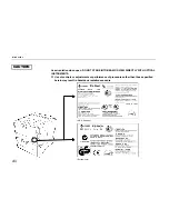
Page 144: ...Chapter 4 Maintenance 4 9 11 Close the top cover...

Page 145: ...ot replacing the toner kit Note ____________________________________________________________________ If the toner container has been replaced when the message Replace Toner Clean printer was displayed...

Page 146: ...Clean according to the following procedure 1 Open the printer s front cover 2 Pull the cleaning knob green located on the main charger unit slowly in and out a few times as shown in the figure This c...

Page 147: ...ged 1 Take the grid cleaner from protective bag in the new toner kit and remove the cap Note ____________________________________________________________________ The grid cleaner pad is impregnated wi...

Page 148: ...ing the grid cleaner slightly lift the main charger unit and repeat the action of slowly pulling the cleaning knob in and out at least five times This will clean the grid inside the main charger unit...

Page 149: ...leaning 4 14 4 When the grid is clean remove the grid cleaner from the printer and dispose of it The grid cleaner is not re usable 5 Close the front cover This ends the charger unit cleaning procedure...

Page 150: ...Do not touch the fuser unit as this may result in a burn injury Print problems such as soiling of the reverse side of printed pages may occur if the paper feed unit becomes dirty Clean the paper feed...

Page 151: ...two or three times as shown in the diagram using the cleaning brush housed in the front panel of the paper feed unit Return the cleaning brush after you have finished using it Cleaning Brush Paper Fee...

Page 152: ...__________________________________________________ Be careful not to touch the transfer roller during cleaning as this may adversely affect print quality 5 When you have finished cleaning the paper fe...

Page 153: ...shooting This chapter explains how to handle printer problems which may occur If a problem cannot be corrected please contact your Kyocera dealer General Guide 5 2 Print Quality Problems 5 4 Indicator...

Page 154: ...roblem may be power related Look through the items below and check anything that seems appropriate Lit See the appropriate item below Check the print quality of a status page if one can be printed No...

Page 155: ...The printer prints a status page but data from the computer is not being printed normally Check the interface cable Connect both ends of the interface cable securely Try replacing the printer cable Fo...

Page 156: ...blank output shown in the table below The troubleshooting procedure for each type of problem is given below If the checks explained in this section do not solve the problem please contact your Kyocera...

Page 157: ...charger wire using the green cleaning knob See Chapter 4 Black or white vertical streaks Check the message in the message display If the Toner low TK 30 message is displayed and the toner indicator is...

Page 158: ...t setting See Chapter 2 Try setting toner control to high density See Chapter 2 If the Toner low TK 30 message is displayed and the toner indicator is flashing See Chapter 4 Clean the charger wire Ope...

Page 159: ...for the assistance of a service person Dirt on the top edge or back of the paper Check the transfer roller Pull out the paper feed unit and check whether the transfer roller is dirty If so print sever...

Page 160: ...paper cassette or multi purpose tray Add paper to the paper feed source See Chapter 1 Lit This indicates either the current paper feeder or the paper output point Flashing A paper jam has occurred in...

Page 161: ...l be indicated number in the message If the maximum of three feeders are installed the upper feeder is 1 the middle feeder is 2 and the bottom feeder is 3 Face down tray paper full The face down tray...

Page 162: ...e appears when the front cover is open during a paper jam Letters A through I and numbers 1 through 6 will appear in place of the s For details on the meaning of the text displayed see page 5 16 A lab...

Page 163: ...apter 1 The printer does not operate when this message is displayed Install MK The maintenance kit MK 30 needs to be replaced Replace the maintenance kit since the total number of printed pages has re...

Page 164: ...y Page protect from the mode select menu and re select Auto Press the CONTINUE key to print data as far as it was stored You can abandon printing by the CANCEL key MEMORY CARD err Insert again The mem...

Page 165: ...given below Note that only error codes 09 and 11 are displayed due to memory card operations made from the control panel 01 Data or memory card capacity is too large This error code appears if an atte...

Page 166: ...ssage display will return to reading Ready 11 The memory card is full of data items The number of data items which can be written on the memory card is limited to 127 Pressing the CANCEL key will rest...

Page 167: ...pressed data is printed due to insufficient memory when FIT flashes in the resolution indicator The quality of printed data is reduced when this occurs FIT will continue flashing even after printing i...

Page 168: ...l cause the message display to change It will now indicate the coded location A through I and 1 through 6 of the paper jam Paper jam C H 1 In this example paper is jammed in the paper feeder C paper f...

Page 169: ...al paper feeder PF 30 E Optional paper feeder PF 30 F Optional paper stacker DF 30 or ST 30 G Face up output tray Face down output tray H Paper feed unit I Optional duplex printing unit DU 30 1 Casset...

Page 170: ...any small pieces of paper in the printer when removing paper jams as this may result in fire Note that data remaining in the printer will be lost if power is turned off while correcting a paper jam Af...

Page 171: ...aper See Figure 5 2 Check the face down output tray If printing stops before a page is completely output carefully remove that sheet of paper H Check the paper feed unit Open the front cover and caref...

Page 172: ...cover This completes taking care of this paper jam Notes ___________________________________________________________________ Sometimes the page on which the paper jam occurred will not be re printed d...

Page 173: ...Chapter 5 Troubleshooting 5 21 Figure 5 1 Paper jam in paper feeder unit Figure 5 2 Paper jam in face up tray Printer s Side Cover Left Face Up Tray Paper Feeder s Side Cover...

Page 174: ...unit Figure 5 4 Paper jammed at the fuser unit Figure 5 5 Paper jammed inside the fuser unit Registration Roller Paper Feed Unit Grasp the tab green to open Fuser Unit Cover Tab green Open this cover...

Page 175: ...Chapter 6 Symbol Set Tables 6 1 Chapter 6 Symbol Set Tables The following tables show all the characters included in the most common symbol sets available...

Page 176: ...HP LaserJet 5 Si Symbol Sets 6 2 HP LaserJet 5Si Symbol Sets LaserJet 5Si Roman 8 8U LaserJet 5Si ECMA 94 Latin 1 0N...

Page 177: ...6 Symbol Set tables 6 3 LaserJet 5Si Legal 1U LaserJet 5Si PC 8 10U To have the printer print the characters of decimal numbers of 7 through 15 and 27 set the printer to the HP PCL transparent mode E...

Page 178: ...12U To have the printer print the characters of decimal numbers of 7 through 15 and 27 set the printer to the HP PCL transparent mode ESC p X To have the printer print the characters of decimal number...

Page 179: ...Chapter 6 Symbol Set tables 6 5 LaserJet 5Si Ventura Math 6M LaserJet 5Si Ventura International 13J...

Page 180: ...HP LaserJet 5 Si Symbol Sets 6 6 LaserJet 5Si Ventura US 14J LaserJet 5Si PS Math 5M...

Page 181: ...Chapter 6 Symbol Set tables 6 7 LaserJet 5Si PS Text 10J LaserJet 5Si Math 8 8M...

Page 182: ...HP LaserJet 5 Si Symbol Sets 6 8 LaserJet 5Si Pi Font 15U LaserJet 5Si MS publishing 6J...

Page 183: ...Chapter 6 Symbol Set tables 6 9 LaserJet 5Si Windows 9U LaserJet 5Si Desktop 7J...

Page 184: ...HP LaserJet 5 Si Symbol Sets 6 10 LaserJet 5Si ISO Latin 2 2N LaserJet 5Si ISO Latin 5 5N...

Page 185: ...Chapter 6 Symbol Set tables 6 11 LaserJet 5Si Windows Latin 1 19U LaserJet 5Si Windows Latin 2 9E...

Page 186: ...HP LaserJet 5 Si Symbol Sets 6 12 LaserJet 5Si Windows Latin 5 5T LaserJet 5Si PC 852 Latin 2 17U...

Page 187: ...Chapter 6 Symbol Set tables 6 13 LaserJet 5Si PC Turkish 9T Macintosh 12J...

Page 188: ...HP LaserJet 5 Si Symbol Sets 6 14 LaserJet 5Si International Characters...

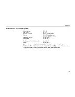
Page 189: ...Appendix A Printer Specifications A 1 Appendix A Printer Specifications...

Page 190: ...PC 603e 100 MHz Main memory 4 MB expandable up to 68 MB with two SIMM slots Supported operating systems Windows 3 1 Windows 95 Windows NT Supported protocols IPX SPX TCP IP DLC Interfaces High speed b...

Page 191: ...erature 10 C to 32 5 C 50 F to 90 5 F Humidity 20 to 80 RH Optimum conditions 20 C 68 F 65 RH Altitude Max 2000m 6500 feet Power supply 120 V 60 Hz max 10 A U S A Canada 220 240 V 50 Hz max 5 A Europe...

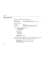
Page 192: ...Appendix B Paper Selection B 1 Appendix B Paper Selection...

Page 193: ...to use copy paper standard paper used in standard dry PPC photocopiers Note ____________________________________________________________________ Some recylced paper does not meet the necessary specifi...

Page 194: ...Squareness of corners 90 0 2 Moisture content 4 to 6 Pulp content 80 or more Note ____________________________________________________________________ Consult with your Kyocera dealer before purchasi...

Page 195: ...to illegible printing misfeeding and paper jams and can shorten the life of the printer Select paper which has as smooth and even a surface as possible Note that use of paper with a surface coating o...

Page 196: ...m JIS B4 257 x 364 mm JIS B5 182 x 257 mm Ledger 11 x 17 inches Letter 8 5 x 11 inches Legal 8 5 x 14 inches Other sizes of paper can be fed from multi purpose tray The minimum size of fed paper is 80...

Page 197: ...blems with paper jams The proper thickness is 0 086 to 0 110 mm 3 4 to 4 3 mils Moisture Content Moisture content is defined as the percent ratio of moisture to the dry mass of the paper Moisture can...

Page 198: ...other if it is stored unwrapped Paper will curl slightly upward when it passes through the fuser unit Load the paper with its natural curl downward so that it will come out flat Some paper also has a...

Page 199: ...reated paper We recommend that you avoid using paper listed below which has been specially treated even if it meets basic specifications If you wish to use such paper test a sample on the printer and...

Page 200: ...al Feeder UF 1 Since the composition and quality of special paper vary considerably special paper is more likely than white bond paper to give trouble during printing Special paper may be used with th...

Page 201: ...ing process 200 C and do not use paper with any kind of surface treatment such as the type of paper commonly used for calendars Overhead Projection OHP Film OHP film must be able to withstand the heat...

Page 202: ...e not of even thickness due to their folded construction It therefore may not be possible to print evenly on an envelope surface in some cases Envelopes which are particularly thick may wrinkle as the...

Page 203: ...struction When selecting labels look for labels whose adhesive will not come in contact with the printer and whose base will not peel off easily Major damage to the printer may result if adhesive gets...

Page 204: ...the signals used in the laser printer s parallel RS 232C RS 422A interfaces It also lists pin assignments signal functions timings connector specificaions and voltage levels The RS 232C RS 422A proto...

Page 205: ...parallel printer cable that complies with the IEEE1284 standards Nibble high default High speed data communication is used in compliance with the IEEE 1284 standard Ordinarily you should leave this s...

Page 206: ...r Pin Assignments Pin In out Description 1 In Strobe nStrobe 2 In Data 0 Data 1 3 In Data 1 Data 2 4 In Data 2 Data 3 5 In Data 3 Data 4 6 In Data 4 Data 5 7 In Data 5 Data 6 8 In Data 6 Data 7 9 In D...

Page 207: ...Strobe Pin 1 A negative going Strobe pulse causes the printer to read and latch the data on the Data 0 1 to Data 7 8 signal lines Data 0 1 to Data 7 8 Pins 2 to 9 These eight signals form the data byt...

Page 208: ...nd On Line signals are not used unless enabled by the FRPO command O2 parameter Auto Feed nAutoFd Pin 14 This signal is used in the Epson version of the Centronics interface to receive a carriage retu...

Page 209: ...not used Power Ready Pin 35 This signal is high when the printer s power is on Select In NSelectIn Pin 36 This signal is used in some versions of the Centronics interface to enable the computer to for...

Page 210: ...2 RS 232C Signal Pin Assignments Pin In out Signal Description 1 FG Frame ground 2 Out TXD Transmit Data 3 In RXD Receive Data 4 Out RTS Request To Send 5 In CTS Clear To Send 6 In DSR Data Set Ready...

Page 211: ...ter to send each signals with a signal ground 5V DC Pin 11 This line is connected to the printer s 5V DC line 5V 0 5V 250 mA Parallel and Serial total maximum fused DTR Data Terminal Ready Pin 20 This...

Page 212: ...ith an RS 422A serial interface Note ____________________________________________________________________ The changing of the main circuit board jumper connector should be carried out only by a Kyocer...

Page 213: ...the rear panel from the Printer 1 Turn the printer s power off Unplug the printer s power cable and disconnect the printer s interface cable from the computer 2 Remove the six screws from the printer...

Page 214: ...am Referring to the diagram set this jumper in the position which matches the serial interface mode to be used In this example the jumper setting is changed from RS 232C to RS 422A 2 After completion...

Page 215: ...a 11 5V DC 18 In RDB Receive data Overview of Signals RS 422A FG Frame Ground Pin 1 This pin is connected directly to the printer frame RDA Receive Data Inverted Pin 3 RDB Receive Data Pin 18 These pi...

Page 216: ...computer differential output RS 422A interface voltage levels The interface signal voltage levels conform with the EIA RS 422A standard The differential voltage varies from 200 mV to 6V SERIAL Connect...

Page 217: ...ndicated on the status printout They can be changed by the FRPO firmware reprogram command described in the Programming Manual The parameters and their identification codes are given below H1 Baud rat...

Page 218: ...ive logic 2 DTR DSR negative logic 3 XON XOFF 4 ETX ACK 5 XON XOFF recognized only as protocol The factory setting is 0 Note ____________________________________________________________________ Since...

Page 219: ...tinuous stream H8 Received data buffer size This is the size of the input buffer specified in units of 10K bytes The factory set value is 6 meaning 60K bytes PRESCRIBE II FRPO D0 command The PRESCRIBE...

Page 220: ...le is a bare shield wire Solder all these shield wires together into a single bundle 3 Using a section of flat wire about 3 mm wide and 15 mm long connect the bundle of shield wires to the metal facin...

Page 221: ...n place 5 Plug the other end of the cable into the computer s RS 232C interface connector 6 Switch on the printer s power 7 The printer s RS 232C parameters are factory set to the following values Bau...

Page 222: ...following commands C MODE COM1 96 N 8 1 P C MODE LPT1 COM1 To test the interface then enter CTRL P C DIR CTRL P The software settings made by the procedures above are temporary On most computers perma...

Page 223: ...setting can be changed 5 Press the and key to select the desired setting 6 Press the ENTER key If you want to re enter a setting press the CANCEL key before pressing the ENTER key 7 Press the EXIT ke...

Page 224: ...IR mode Medium Printer Reset Read fonts Continued from previous page CR action CR only Number of pages printed 012345 MP tray mode Cassette Duplex mode None MP tray size A4 or Letter Univ paper size D...

Page 225: ...e final page Once this preset amount of time has elapsed the printer will automatically issue a form feed This timeout setting can be set in 5 second increments up to 495 seconds Drum Print Status Pag...

Reviews: