

1-5-22
Code
Contents
Remarks
Causes
Check procedures/corrective measures
FS-9120DN/9520DN
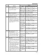
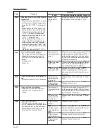
6050
6400
6410
6420
7300
Abnormally low fuser unit thermistor
temperature
• When only fuser heater M is on, fuser
unit thermistor 2 detects temperature
lower than 80 °C/176 °F during print-
ing.
• When fuser heater M and fuser unit
heater S are on, fuser unit thermistor
2 detects temperature lower than 80
°C/176 °F or fuser unit thermistor 1
detects temperature lower than 100
°C/212 °F during ptinting.
• The detection history of "6050" is
stored. If "6050" is detected several
times continuously, when the power
switch is turned on next, "6050" is im-
mediately displayed and the machine
stops.
(Method of clearing: See P.1-5-15.)
Zero-crossing signal problem
• The engine controller PWB does not
detect the zero-crossing signal (Z
CROSS SIG) for the time specified
below.
At power-on: 5 s
Others: 5 s
Fuser unit connector insertion prob-
lem
• Absence of the fuser unit is detected.
Fuser unit fuse cut problem
• When you try to cut the fuser fuse,
the fuse is not cut even after 3 s
elapse.
Toner sensor problem
• While the toner container sensor is
on, the toner sensor in the developing
unit does not turn on after the toner
sensor turns off and toner is replen-
ished from the toner container.
Broken fuser
heater M or S
wire.
Poor contact in
the connector ter-
minals.
Defective power
supply unit.
Defective engine
controller PWB.
Fuser unit con-
nector inserted
incorrectly.
Defective fuser
unit connector.
Poor contact in
the connector ter-
minals.
Fuser unit con-
nector inserted
incorrectly.
Defective toner
sensor.
Poor contact in
the toner sensor
connector termi-
nals.
Defective toner
container sensor.
Defective toner
container.
Check for continuity. If none, replace the
fuser heater M or S (see page 1-6-20).
Check the connection of connectors YC1-3
on the engine controller PWB and YC2-6
on the power supply unit, and the continu-
ity across the connector terminals. Repair
or replace if necessary.
Check if the zero-crossing signal is output
from YC2-6 on the power supply unit. If
not, replace the power supply unit.
Replace the engine controller PWB if
C6400 is detected while YC2-6 on the
power supply unit outputs the zero-cross-
ing signal.
Reinsert the fuser unit connector if neces-
sary.
Replace the fuser unit.
Check the connection of connector YC10
on the engine controller PWB and the con-
tinuity across the connector terminals. Re-
pair or replace if necessary.
Reinsert the fuser unit connector if neces-
sary.
Replace the toner sensor.
Reinsert the connector. Also check for con-
tinuity within the connector cable. If none,
remedy or replace the cable.
Replace the toner container sensor.
Replace the toner container.


