background image

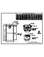
7. INSTALLING KC MODULES

The frame of each module has 0.28

φ

 diameter (7 mm) mounting holes (Refer to Module Mounting Specifications).

These are used to secure the modules to the supporting structure. An example of a ground mounted structure is shown
in Figure 3. The four holes close to the corners of the module are most often used for attachment. Refer to the
Mounting Specification Specifications for the position of these holes. Clearance between the module frame and the
mounting surface may be required to prevent the junction box from touching the surface, and to circulate cooling air
around the back of the module. If the modules are to be installed on the roof or wall of a building, the standoff method
or the rack method is recommended.

STAND-OFF METHOD:  The modules are supported
parallel to the surface of the building wall or roof.
Clearance between the module frames and surface of
the wall or roof is required to prevent wiring damage
and to allow air to circulate behind the module.
The recommended stand-off height is 4.5 in. (about 115
mm) If other mounting means are employed, this may
affect the Listing For Fire Class Ratings.

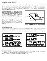
RACK:  The supporting frame is used to mount
modules at correct tilt angles. The modules are not
designed for integral mounting as part of a roof or wall.
The mounting design may have an impact on the fire
resistance.

FOOT ANGLE

SUPPORT

LEGS

MOUNTING HOLE

ARRAY FRAME

MODULE

Figure 2.  Basic Rack or Standoff Mounting Structure
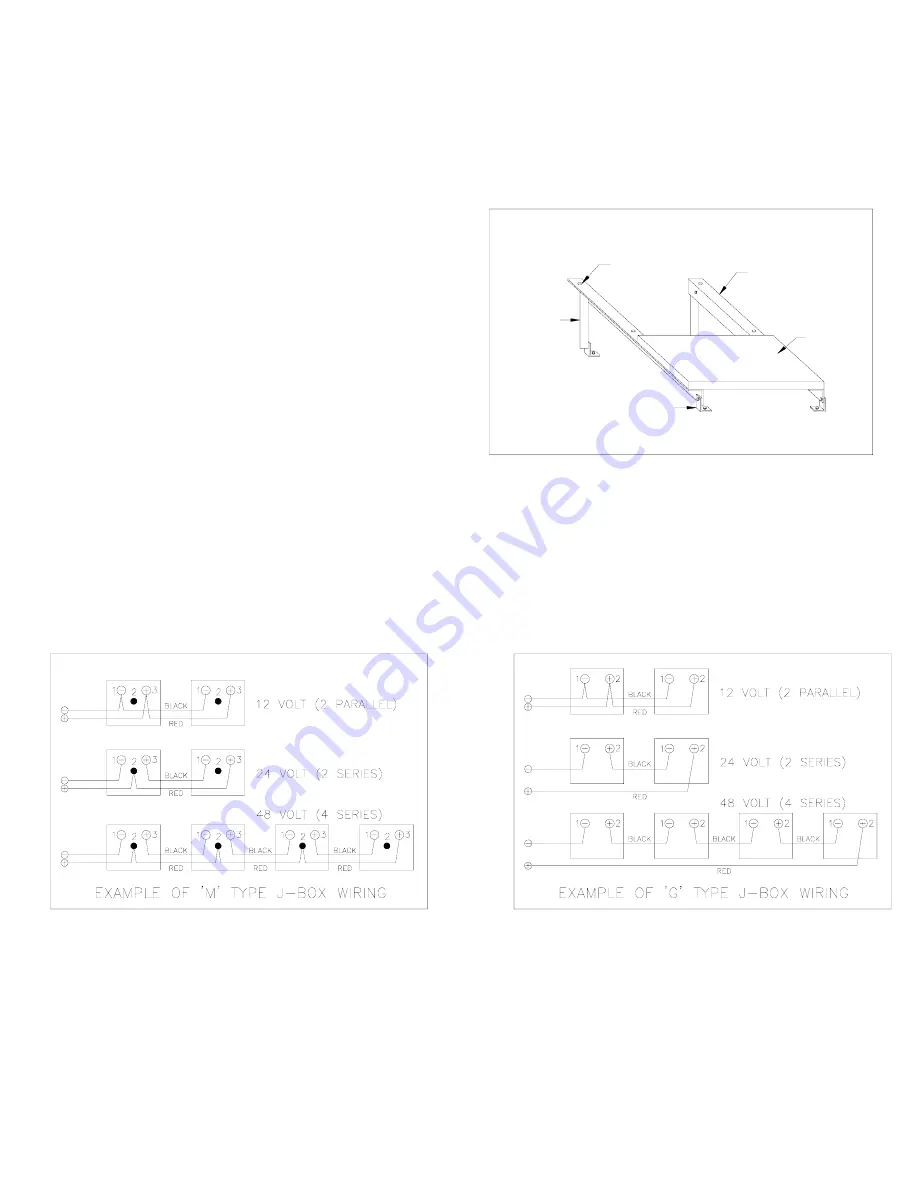
8. MODULE WIRING

As shown in Module Mounting Specifications, all of the KC modules utilize the Type G junction box except the KC-70,
KC-80 and KC-120-1 modules which utilize the Type M junction box (see J-box details). This junction box, located on
the back side of the module, is weatherproof and is designed to be used with standard wiring or conduit connections.
Kyocera recommends that all wiring and electrical connections comply with the 1999 National Electrical Code (NEC).
Bypass diodes and cable clamps are included with each module when shipped from the factory.

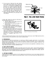
Figure 3.  Standard Wiring Examples

To wire Kyocera modules:
A

Determine the nominal system array voltage of your system. Each panel is equivalent to a 12 VDC nominal block.
Standard array voltages 12, 24 and 48 volt are shown as examples in Figure 3.

B.  Open the "G" or "M" box cover by loosening the screws in the cover.

Summary of Contents for KC-120-1

Page 1: ...erate most efficiently in sunlight Kyocera modules are ideal to power remote homes recreational vehicles water pumps telecommunication systems and many other applications either with or without the use of storage batteries 4 WARNINGS Solar modules generate electricity when exposed to light Arrays of many modules can cause lethal shock and burn hazards Only authorized and trained personnel should h...

Page 2: ...ulated and ventilated battery case specifically designed for the purpose 5 SITE SELECTION In most applications KC modules should be installed in a location where they will receive maximum sunlight throughout the year In the Northern Hemisphere the modules should typically face south and in the Southern Hemisphere the modules should typically face north Modules facing 30 degrees away from true Sout...

Page 3: ...means are employed this may affect the Listing For Fire Class Ratings RACK The supporting frame is used to mount modules at correct tilt angles The modules are not designed for integral mounting as part of a roof or wall The mounting design may have an impact on the fire resistance FOOT ANGLE SUPPORT LEGS MOUNTING HOLE ARRAY FRAME MODULE Figure 2 Basic Rack or Standoff Mounting Structure 8 MODULE ...

Page 4: ...fuse is 4 12 amperes Figure 5 Interconnect Cable Clamp H After checking that module wiring is correct close and secure all the junction boxes Use a Phillips head screw driver to secure all screws on the junction box cover to ensure a waterproof seal 9 GROUNDING We recommend you attach all module frames to an earth ground Attach a separate ground wire to one of the holes marked ground on the module...

Page 5: ... connections will result in a damaged module or array 13 SPECIFICATIONS The electrical and physical specifications can be found at the end of this document Table 2 NOTES The electrical characteristics are within 10 percent of indicated values of Isc Voc and Pmax under standard test conditions irradiance of 1KW m2 AM 1 5 spectrum and cell temperature of 25 Under certain conditions a photovoltaic mo...

Page 6: ...ectrical specifications are under test conditions of irradiance of 1kW M2 Spectrum of 1 5 air mass and cell temperature of 25o C Physical Characteristics Model Number KC 120 1 KC 80 KC 70 KC 60 KC 50 KC 45 KC 40 KC 35 Length Inches mm 56 1 1425 38 4 976 34 1 865 29 6 751 25 2 639 22 6 573 20 7 526 18 5 471 Width Inches mm 25 7 652 25 7 652 25 7 652 25 7 652 25 7 652 25 7 652 25 7 652 25 7 652 Dept...

Page 7: ...MODULE MOUNTING DIMENSIONS MODULE MOUNTING SPECIFICATIONS DO NOT USE DO NOT USE KYOCERA KC SERIES ...

Reviews: