3NF
1-5-12
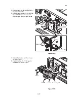
5. Remove the connector and the band of
PF paper feed motor.
6. Remove the connector (YC15) from the
PF main PWB and then release the
electrical wires from two wire saddles.
Figure 1-5-19
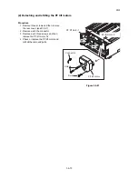
7. Remove four screws and then remove
the PF driving unit.
8. Check or replace the PF driving unit
and refit all the removed parts.
Figure 1-5-20
Wire saddle
Connector
Band
YC15
PF main PWB
PF main PWB
Screws
PF driving unit
Screw
Screw
Summary of Contents for PF-740
Page 1: ...SERVICE MANUAL Published in April 2011 843NF111 3NFSM061 Rev 1 PF 740...
Page 3: ...Revision history Revision Date Replaced pages Remarks 1 6 April 2011 CONTENTS 2 4 1 to 2 4 3...
Page 4: ...This page is intentionally left blank...
Page 10: ...This page is intentionally left blank...
Page 15: ...3NF 1 1 3 1 1 3 Machine cross section Figure 1 1 2 Paper path...
Page 16: ...3NF 1 1 4 This page is intentionally left blank...
Page 26: ...3NF 1 2 10 This page is intentionally left blank...
Page 76: ...3NF 1 5 14 This page is intentionally left blank...
Page 86: ...3NF 2 2 4 This page is intentionally left blank...
Page 92: ...3NF 2 3 6 This page is intentionally left blank...
Page 96: ...2011...
Page 97: ...2011...


