background image

3NC/3NB/3NK

1-4-22

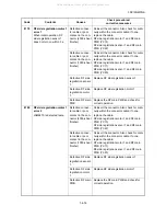
(5)
DF eject motor 
does not operate.

1. Defective connector 

cable or poor con-
tact in the connector.

Reinsert the connector. Also check for continuity within the 
connector cable. If none, replace the cable.
DF eject motor and DF main PWB (YC10)

2. Defective drive trans-

mission system.

Check if the rollers and gears rotate smoothly. If not, 
grease the bushes and gears. Check for broken gears and 
replace if any.

3. Defective motor.

Replace the DF eject motor.

4. Defective PWB.

Replace the DF main PWB and check for correct operation 
(see page 1-5-4).

(6)
DF adjustment 
motor 1,2 does not 
operate.

1. Defective connector 

cable or poor con-
tact in the connector.

Reinsert the connector. Also check for continuity within the 
connector cable. If none, replace the cable.
DF adjustment motor 1,2 and DF main PWB (YC10)

2. Defective drive trans-

mission system.

Check if the rollers and gears rotate smoothly. If not, 
grease the bushes and gears. Check for broken gears and 
replace if any.

3. Defective motor.

Replace the DF adjustment motor 1,2.

4. Defective PWB.

Replace the DF main PWB and check for correct operation 
(see page 1-5-4).

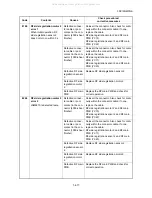
(7)
Slide motor does 
not operate.

1. Defective connector 

cable or poor con-
tact in the connector.

Reinsert the connector. Also check for continuity within the 
connector cable. If none, replace the cable.
Slide motor and DF main PWB (YC10)

2. Defective drive trans-

mission system.

Check if the rollers and gears rotate smoothly. If not, 
grease the bushes and gears. Check for broken gears and 
replace if any.

3. Defective motor.

Replace the slide motor.

4. Defective PWB.

Replace the DF main PWB and check for correct operation 
(see page 1-5-4).

(8)
DF tray motor does 
not operate.

1. Defective connector 

cable or poor con-
tact in the connector.

Reinsert the connector. Also check for continuity within the 
connector cable. If none, replace the cable.
DF tray motor and DF main PWB (YC14)

2. Defective drive trans-

mission system.

Check if the rollers and gears rotate smoothly. If not, 
grease the bushes and gears. Check for broken gears and 
replace if any.

3. Defective motor.

Replace the DF tray motor.

4. Defective PWB.

Replace the DF main PWB and check for correct operation 
(see page 1-5-4).

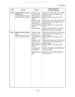
Problem

Causes

Check procedures/corrective measures

All manuals and user guides at all-guides.com

Summary of Contents for PH-7A

Page 1: ...SERVICE MANUAL Published in January 2011 843NC110 3NCSM060 First Edition DF 770 AK 730 PH 7A 7C 7D All manuals and user guides at all guides com a l l g u i d e s c o m...

Page 2: ...your area for proper disposal ATTENTION IL Y A UN RISQUE D EXPLOSION SI LA BATTERIE EST REMPLACEE PAR UN MODELE DE TYPE INCORRECT METTRE AU REBUT LES BATTERIES UTILISEES SELON LES INSTRUCTIONS DONNEES...

Page 3: ...Revision history Revision Date Replaced pages Remarks All manuals and user guides at all guides com...

Page 4: ...This page is intentionally left blank All manuals and user guides at all guides com...

Page 5: ...fety of their customers their machines as well as themselves during maintenance activities Service personnel are advised to read this booklet carefully to familiarize themselves with the warnings and...

Page 6: ...r damage to property may result from insufficient attention to or incorrect com pliance with warning messages using this symbol Symbols The triangle symbol indicates a warning including danger and cau...

Page 7: ...y cause fire or electric shock Do not install the copier near a radiator heater other heat source or near flammable material This may cause fire Allow sufficient space around the copier to allow the v...

Page 8: ...that the copier is correctly connected to an outlet with a ground connection Check that the power cable covering is free of damage Check that the power plug is dust free If it is dirty clean it to rem...

Page 9: ...ng screws Check that all the caution labels that should be present on the machine according to the instruction handbook are clean and not peeling Replace with new ones if necessary Handle greases and...

Page 10: ...This page is intentionally left blank All manuals and user guides at all guides com...

Page 11: ...te 1 4 89 2 No image appears entirely black 1 4 90 3 Image is too light 1 4 91 4 The background is colored 1 4 91 5 White streaks are printed vertically 1 4 92 6 Black streaks are printed vertically 1...

Page 12: ...recautions 1 5 1 1 5 2 Document finisher section 1 5 2 1 Detaching and refitting the front cover and rear cover 1 5 2 2 Detaching and refitting the PF main PWB 1 5 3 3 Detaching and refitting the Stap...

Page 13: ...or 20 sheets A3 B4 Ledger Legal 8K 300 sheets 15 30 sets A4R LetterR 400 sheets 20 40 sets A4 B5 Letter 16K 400 sheets 20 40 sets When stapling 21 or 30 sheets A3 B4 Ledger Legal 8K 500 sheets 16 25...

Page 14: ...K 1 1 2 1 1 2 Parts names 1 Document Finisher Figure 1 1 1 5 2 1 3 4 1 DF Main tray tray A 2 DF tray extension 3 DF top cover 4 DF Sub tray tray B 5 DF Front cover All manuals and user guides at all g...

Page 15: ...NB 3NK 1 1 3 2 Bridge unit Figure 1 1 2 2 1 4 3 5 1 Bridge eject cover 2 Bridge conveying unit 3 Bridge conveying cover 4 Bridge drive unit 5 Bridge entry unit All manuals and user guides at all guide...

Page 16: ...1 1 3 Machine cross section Figure 1 1 3 2 1 3 4 Paper path 1 DF processing section 2 Eject tray section 3 Bridge unit section 4 Punch unit Option All manuals and user guides at all guides com a l l...

Page 17: ...erature and low humidity an abrupt change in the environmental temperature and cool or hot direct air Avoid places subject to dust and vibrations Choose a surface capable of supporting the weight of t...

Page 18: ...cument Finisher 5 Spacer A 6 Plastic sheet 7 Plastic sheet 8 Outer case 9 Upper right pad 10 Upper left pad 11 Spacer B 12 Finisher tray 13 Spacer C 14 Lower earth plate 15 Wire guide 16 Staple cartri...

Page 19: ...e entry unit 5 Bridge drive unit 6 Bridge eject unit 7 Spacer A 8 Spacer B 9 Top spacer 10 Left connevtion cover 11 Upper front cover 12 Left scanner cover 13 Lower connevtion cover 14 Left cover 15 F...

Page 20: ...3NB 3NK 1 2 4 2 Removing the tapes and pads 1 Remove tape from the finisher try Figure 1 2 3 2 Remove tape from the document finisher Figure 1 2 4 Tape Tape All manuals and user guides at all guides...

Page 21: ...3NC 3NB 3NK 1 2 5 3 Open the DF front cover Figure 1 2 5 4 Remove four tapes Figure 1 2 6 DF front cover Tape Tape Tape Tape All manuals and user guides at all guides com a l l g u i d e s c o m...

Page 22: ...3NK 1 2 6 5 Remove tape from the DF rear cover Figure 1 2 7 6 Remove the lid rear cover and then remove tape Figure 1 2 8 Tape DF rear cover Tape Lid rear cover All manuals and user guides at all gui...

Page 23: ...NC 3NB 3NK 1 2 7 7 Remove tape from the bridge entry unit Figure 1 2 9 8 Remove five tapes from bridge convey ing unit Figure 1 2 10 Tape Tapes Tape Tapes All manuals and user guides at all guides com...

Page 24: ...3NB 3NK 1 2 8 9 Remove two tapes from the bridge eject unit Figure 1 2 11 10 Remove three tapes and two pads Figure 1 2 12 Tape Tape Pad Pad Tape Tape Tape All manuals and user guides at all guides c...

Page 25: ...3NC 3NB 3NK 1 2 9 11 Remove tape from the bridge drive unit Figure 1 2 13 Tape All manuals and user guides at all guides com...

Page 26: ...3NC 3NB 3NK 1 2 10 This page is intentionally left blank All manuals and user guides at all guides com a l l g u i d e s c o m...

Page 27: ...maintenance item number using the cursor up down keys or numeric keys The selected maintenance item is run Press the stop key Press the start key Start End Maintenance mode is entered The maintenance...

Page 28: ...aintenance modes item list Section Item No Content of maintenance item Initial setting General U019 Displaying the ROM version Others U905 Checking counts by optional devices All manuals and user guid...

Page 29: ...nner Boot Scanner booting RFID RFID ROM IH CPU IH CPU ROM IH CPU Boot IH CPU booting Motor CPU Motor CPU ROM Motor CPU Boot Motor CPU booting Dictionary Option Language Optional language ROM PDF1 7 Re...

Page 30: ...Side large capacity feeder booting DF 1000 sheet finisher 4000 sheet finisher ROM DF Boot 1000 sheet finisher 4000 sheet finisher booting PH Punch unit ROM PH Boot Punch unit booting MT Mailbox ROM M...

Page 31: ...DP Counts of DP DF Counts of 1000 sheet or 4000 sheet finisher Display Description ADP No of single sided originals that has passed through the DP RADP No of double sided originals that has passed th...

Page 32: ...3NC 3NB 3NK 1 3 6 This page is intentionally left blank All manuals and user guides at all guides com...

Page 33: ...misfeed indication A D H D K K K L L L L J J G J J H I F J J J J B C E E F C C A Misfeed in cassette 1 B Misfeed in cassette 2 C Misfeed in cassette 3 or 4 option D Misfeed in the MP tray E Misfeed in...

Page 34: ...3NC 3NB 3NK 1 4 2 2 Paper misfeed detection condition Figure 1 4 2 Paper jam location DFEPS DFMES DFPES BRES BRCS2 BRCS1 All manuals and user guides at all guides com...

Page 35: ...er F 4904 Bridge conveying sensor 1 BRCS1 does not turn on during paper feed from cassette 4 paper feeder F 4905 Bridge conveying sensor 1 BRCS1 does not turn on during paper feed from cassette 5 SMT...

Page 36: ...eed from duplex section I 4919 Bridge conveying sensor 1 BRCS1 does not turn off during paper feed from MP tray I 5001 Bridge conveying sensor 2 non arrival jam Bridge conveying sensor 2 BRCS2 does no...

Page 37: ...side paper feeder I 5017 Bridge conveying sensor 2 BRCS2 does not turn off during paper feed from cassette 7 side paper feeder I 5018 Bridge conveying sensor 2 BRCS2 does not turn off during paper fee...

Page 38: ...16 Bridge eject sensor BRES does not turn off dur ing paper feed from cassette 6 side paper feeder I 5117 Bridge eject sensor BRES does not turn off dur ing paper feed from cassette 7 side paper feede...

Page 39: ...ensor non arrival jam DF sub eject sensor DFSES does not turn on within specified time of DF paper entry sensor DFPES turning on J 6210 DF sub eject sensor stay jam DF sub eject sensor DFSES is not tu...

Page 40: ...per surface sensor DFTUSS does turned on when the power is turned on or cover close 4000 sheet finisher J 6421 DF tray upper surface sensor DFTUSS does turned on when the power is turned on or cover c...

Page 41: ...sensor DFSTS is not turned on within specified time after driving the DF staple motor DFSTM 4000 sheet finisher J 7001 DF staple sensor DFSTS is not turned on within specified time after driving the...

Page 42: ...machine stops print ing and display an error message on the operation panel An error message consists of a message prompting a contact to service personnel and a four digit error code indicating the...

Page 43: ...and punch PWB YC8 Punch PWB YC1 and DF main PWB YC8 Defective punch home position sen sor Replace the punch home position sensor Defective punch motor Replace the punch motor Defective PWB Replace the...

Page 44: ...for correct operation 8090 DF paddle motor error When the DF paddle motor is driven DF paddle sensor does not turn on within 1 s Defective connec tor cable or poor contact in the con nector 4000 sheet...

Page 45: ...e DF shift motor 1 is driven DF shift sensor 1 does not turn on within 160 ms Defective connec tor cable or poor contact in the con nector Reinsert the connector Also check for conti nuity within the...

Page 46: ...n 20 s Defective connec tor cable or poor contact in the con nector 4000 sheet finisher Reinsert the connector Also check for conti nuity within the connector cable If none replace the cable DF tray m...

Page 47: ...ce sensor Defective DF tray motor Replace the DF tray motor Defective DF main PWB Replace the DF main PWB and check for correct operation 8160 DF tray motor error 3 When the main tray has descended DF...

Page 48: ...otor 1 Defective DF main PWB Replace the DF main PWB and check for correct operation 8180 DF side registration motor 1 error 2 JAM6810 is detected twice Defective connec tor cable or poor contact in t...

Page 49: ...otor 2 Defective DF main PWB Replace the DF main PWB and check for correct operation 8200 DF side registration motor 2 error 2 JAM6910 is detected twice Defective connec tor cable or poor contact in t...

Page 50: ...nsor Defective DF slide motor Replace the DF slide motor Defective DF main PWB Replace the DF main PWB and check for correct operation 8230 DF staple motor error JAM7000 is detected twice Defective co...

Page 51: ...ert the connector Also check for conti nuity within the connector cable If none replace the cable Punch slide motor and punch PWB YC3 Punch PWB YC1 and DF main PWB YC7 Defective connec tor cable or po...

Page 52: ...for correct operation 8900 Document finisher backup error Read and write data does not match 3 times in succession Defective connec tor cable or poor contact in the con nector 4000 sheet finisher Rein...

Page 53: ...If not grease the bushes and gears Check for broken gears and replace if any 3 Defective motor Replace the DF middle eject motor 4 Defective PWB Replace the DF main PWB and check for correct operatio...

Page 54: ...tive PWB Replace the DF main PWB and check for correct operation see page 1 5 4 7 Slide motor does not operate 1 Defective connector cable or poor con tact in the connector Reinsert the connector Also...

Page 55: ...ace the bridge solenoid 3 Defective PWB Replace the engine PWB and check for correct operation 11 A paper jam is indicated when the main power switch is turned on 1 A piece of paper torn from paper is...

Page 56: ...eying roller Paper conveying pulley Clean with isopropyl alcohol Check if the surfaces of the following roll ers are dirty with paper powder Bridge section Feedshift roller Feedshift pulley Clean with...

Page 57: ...4 25 2 Abnormal noise is heard Check if the rollers pulleys and gears operate smoothly Grease the bushes and gears Problem Causes check procedures Corrective measures All manuals and user guides at a...

Page 58: ...3NC 3NB 3NK 1 4 26 This page is intentionally left blank All manuals and user guides at all guides com...

Page 59: ...the wall outlet When handling PWBs printed wiring boards do not touch parts with bare hands The PWBs are susceptible to static charge Do not touch any PWB containing ICs with bare hands or any object...

Page 60: ...er Procedure 1 Open the DF front cover 2 Remove three screws and then remove the DF front cover Assemble Figure 1 5 1 3 Remove screw and then remove the Lid rear cover Figure 1 5 2 DF front cover DF f...

Page 61: ...3NC 3NB 3NK 1 5 3 4 Remove two screws and then remove the DF rear cover Figure 1 5 3 DF rear cover Screw Screw All manuals and user guides at all guides com a l l g u i d e s c o m...

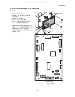
Page 62: ...eplace the DF main PWB and refit all the removed parts CAUTION when replacing the DF main PWB remove the EEPROM U4 from the DF main PWB that has been removed and then reattach it to the new DF main PW...

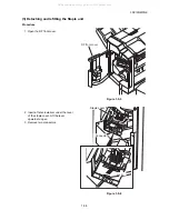
Page 63: ...ure 1 Open the DF front cover Figure 1 5 5 2 Insert a flat screwdriver under the lever of the staple cover Lift the lever upwards to open 3 Remove two connectors Figure 1 5 6 DF front cover Connectors...

Page 64: ...1 5 6 4 Raise the front of the staple unit and pull the staple unit frontwards 5 Check or replace the Staple unit and refit all the removed parts Figure 1 5 7 Hook All manuals and user guides at all...

Page 65: ...marks on finisher PWB replacement When replacing the finisher PWB remove the EEPROM U4 from the finisher PWB that has been removed and then reattach it to the new finisher PWB Figure 1 6 1 U4 DF main...

Page 66: ...3NC 3NB 3NK 1 6 2 This page is intentionally left blank All manuals and user guides at all guides com a l l g u i d e s c o m...

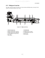
Page 67: ...e 2 1 1 Bridge unit section 5 1 1 1 3 4 6 5 2 2 2 7 8 9 10 11 13 12 1 Paper conveying roller 2 Paper conveying pulley 3 Bridge conveying sensor1 BRCS1 4 Bridge conveying sensor2 BRCS2 5 Actuator Bridg...

Page 68: ...m BRCM 2 BRCS2 BRCS1 BRCM 1 BRES BRSOL YC6 2 YC4 2 YC3 YC1 YC7 1 2 3 4 YC7 5 6 7 8 BRIDGE_SENS1 BRIDGE1_B A B A BRIDGE2_B A B A BRPWB BRIDGE_SENS2 EPWB YC20 12 13 YC20 17 YC20 YC20 EXIT_SOL_RET EXIT_S...

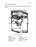
Page 69: ...2 1 3 Processing section 7 6 5 9 11 10 8 1 2 3 4 12 13 14 16 15 1 Middle roller 2 Middle pulley 3 DF entrance sensor DFPES 4 DF middle sensor DFMS 5 Actuator DF middle sensor 6 Middle eject roller 7 M...

Page 70: ...BUNDLE SENS SIG MID EJE SENS SIG SIDE REG F SENS SIG SIDE REG R SENS SIG PADDLE SENS SIG SIDE REG R MOT 2B 1B 2A 1A SIDE REG F MOT 2B 1B 2A 1A EJECT MOT 2B 1B 2A 1A STAPLE SENS SIG ST MOV MOT 2B 1B 2A...

Page 71: ...ying guide lowers and the paper is fed to the adjustment tray by paddle DF adjustment motors 1 and 2 activate the adjustment guide to adjust the paper 3 When adjustment of the last sheet of the bundle...

Page 72: ...etected with the DF tray sensor 1 2 3 DFTS1 2 3 Also the paper stock quantity is detected with the DF tray surface sensor 1 2 DFTUSS1 2 Figure 2 1 6 Eject tray section 4 3 5 9 8 6 7 1 2 1 DF tray surf...

Page 73: ...gure 2 1 7 Eject tray section block diagram YC14 1 2 YC20 15 DFMPWB DFTM TRY MOT OUT1A 1B TRY HP SENS SIG TRY HALF SENS SIG TRY FULL SENS SIG DFTS1 DFTS2 DFTS3 YC20 9 YC20 12 All manuals and user guid...

Page 74: ...1 8 2 1 4 Punch unit Option Figure 2 1 8 Punch unit 1 4 5 2 3 1 Punch cam 2 Punch cutter 3 Punch waste box 4 Punch home position sensor PUHPS 5 Punch plus sensor PUPS All manuals and user guides at a...

Page 75: ...YC8 3 PUHPS PHMOT_HP YC8 6 YC8 YC7 PUM PHMOT_N P YC1 1 3 YC2 2 YC1 PUSLM PUSLS PUPES2 PUPES1 PUSOL PUTFS YC5 10 YC5 2 3 YC7 1 YC6 3 YC5 2 3 4 5 YC3 1 2 3 4 PHTNK_FUL PHSOL_PUL RET PHLED_A B C D PHADJ_...

Page 76: ...3NC 3NB 3NK 2 1 10 This page is intentionally left blank All manuals and user guides at all guides com a l l g u i d e s c o m...

Page 77: ...Electrical Parts Layout 2 2 1 Electrical parts layout 1 PWBs Figure 2 2 1 PWBs 1 DF main PWB DFMPWB Controls electrical components 1 Machine front Machine inside Machine rear All manuals and user gui...

Page 78: ...ion of the bundle discharge unit 8 DF paddle sensor DFPDS Detects the position of the paddle 9 DF tray sensor 1 DFTS1 Detects the eject tray reaching the home position 10 DF tray sensor 2 DFTS2 Detect...

Page 79: ...roller 5 DF side registration motor 1 DFSRM1 Drives the front registration plate 6 DF side registration motor 2 DFSRM2 Drives the rear registration plate 7 DF eject motor DFEM Drives the eject roller...

Page 80: ...cts a paper misfeed in the bridge eject section 5 Bridge conveying unit switch BRCUSW Detects opening closing of the bridge cover 6 Bridge eject cover switch BRECSW Detects opening closing of the brid...

Page 81: ...t 5 Punch tank full sensor PUTFS Detects when the punch waste tank is full 6 Punch paper edge sensor1 PUPES1 Detects the side edge position of the paper 7 Punch paper edge sensor2 PUPES2 Detects the s...

Page 82: ...3NC 3NB 3NK 2 2 6 This page is intentionally left blank All manuals and user guides at all guides com...

Page 83: ...put from Machine YC6 1 24V1 O 24 V DC 24 V DC power outoput to DFFCSW Connected to the DF front cover switch and DF top cover switch 2 FRONT COV SIG I 0 24 V DC DFFCSW On Off 3 TOP COV SOURCE O 0 24 V...

Page 84: ...input 12 PU DO O 0 3 3 V DC pulse Serial communication data signal output YC9 1 GND Ground Connected to the Punch unit PWB 2 24V2 O 24 V DC 24 V DC power output YC10 1 EJECT MOT 2B O 0 24 V DC pulse D...

Page 85: ...to the DF paddle motor DF side registration motor 2 1 2 PADDLE MOT 1B O 0 24 V DC pulse DFPDM drive control signal 3 PADDLE MOT 2A O 0 24 V DC pulse DFPDM drive control signal 4 PADDLE MOT 1A O 0 24 V...

Page 86: ...taple unit HP signal YC14 1 TRY MOT OUT1A O 0 24 V DC pulse DFTM drive control signal Connected to the DF tray motor 2 TRY MOT OUT1B O 0 24 V DC pulse DFTM drive control signal YC18 1 3 3V O 3 3V DC 3...

Page 87: ...SIG I 0 3 3V DC DFTS2 On Off 13 TRY FULL SENS A O 3 3V DC 3 3 V DC power output to DFTS3 14 GND Ground 15 TRY FULL SENS SIG I 0 3 3V DC DFTS3 On Off 16 PADDLE SENS A O 3 3V DC 3 3 V DC power output to...

Page 88: ...O 0 5V DC BRCUSW On Off 3 BRIDGE_SENS 2 O 0 5V DC BRCS2 On Off 4 BRIDGE1 DIR I 0 5V DC BRCM1 control signal 5 BRIDGE1 PD I 0 5V DC BRCM1 control signal 6 BRIDGE1 CLK I 0 5V DC pulse BRCM1 clock signal...

Page 89: ...DC 5 V DC power output to BRCUSW 7 NC Not used YC7 1 BRIDGE1_B O 0 24V DC pulse BRCM1 control signal Connected to the bridge conveying motor1 2 2 BRIDGE1_A O 0 24V DC pulse BRCM1 control signal 3 BRID...

Page 90: ...3 3V DC Select signal from the machine 5 PH_RDY O 0 3 3V DC Ready signal to the machine 6 PHMOT_REQ I 0 3 3V DC PUM On Off 7 PHPES_REQ O 0 3 3V DC PUPES On Off 8 GND Ground 9 GND Ground 10 3 3V I 3 3V...

Page 91: ..._A On Off 5 PHLED_B O 0 3 3V DC PUPES1_B On Off 6 PHLED_C O 0 3 3V DC PUPES1_C On Off 7 PHLED_D O 0 3 3V DC PUPES1_D On Off 8 PHLED_3 3V O 3 3V DC 3 3 V DC power output to PUPES1 9 5 0V O 5V DC 5 V DC...

Page 92: ...C 3NB 3NK 2 3 10 YC9 1 PHTNK_SET I 0 3 3V DC PUTSSW On Off Connected to the punch tank set switch 2 GND Ground Connector Pin Signal I O Voltage Description All manuals and user guides at all guides co...

Page 93: ...PADDLE MOT 1B PADDLE MOT 2A PADDLE MOT 1A SIDE REG R MOT 2B SIDE REG R MOT 1B SIDE REG R MOT 2A SIDE REG R MOT 1A SIDE REG F MOT 2B SIDE REG F MOT 1B SIDE REG F MOT 2A SIDE REG F MOT 1A 7 8 10 19 18...

Page 94: ...17 16 8 BRIDGE2 DIR 5 13 12 BRIDGE_SENS 2 BRIDGE1 DIR BRIDGE1 PH BRIDGE1 REM 3 BRIDGE OPEN 2 3 BRIDGE1 DIR 5 15 BRIDGE2 PD BRIDGE2 MODE 13 19 BRIDGE2 CLK BRIDGE2 REM 7 11 12 10 8 9 6 7 4 3 16 19 5 1...

Page 95: ...1 1 PHADJ_ HP PHADJ_ MOT 1B 2 PH_ CLK 2 PHADJ_ MOT 2B 1 1 SENS3 3V 1 1 YC6 2 2 PHADJ_ HP 3 3 YC5 24V2 1 PHSOL_ PUL 2 2 PHSOL_ RET PHSOL_ PUL 24V2 SENS3 3V PHADJ_ MOT_ An PHADJ_ MOT_ Bn PHADJ_ MOT_ A...

Page 96: ...2011 All manuals and user guides at all guides com a l l g u i d e s c o m...

Page 97: ...2011 All manuals and user guides at all guides com...

Reviews: