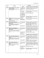
2JZ/2JX/2JV/2H7-1
1-4-44
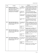
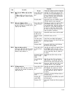
C6010
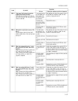
Abnormally high fuser thermistor
temperature
The fuser Abnormally high signal is
detected for 60 s or more.
Defective PWB.
Replace the power source PWB or engine
PWB and check for correct operation.
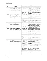
C6020
Abnormally high fuser thermistor 1
temperature
The fuser temperature exceeds 240
C/
464
F for 1 s.
Installation defec-
tiveness on fuser
thermistor 1.
Measure the resistance. If it is
, replace
the fuser unit (see page 1-5-41).
Defective PWB.
Replace the power source PWB or engine
PWB and check for correct operation.
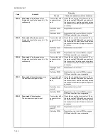
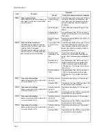
C6030
Fuser thermistor 1 break error
During warming up, fuser thermistor 1
does not detect temperature rise of 1
C/
1.8
F for 10 s.
When the difference of temperature of
fuser thermistor 1 and 2 becomes 100
C/212
F or more.
Defective fuser
heater 1.
Check for continuity across each heater. If
none, replace the fuser unit (see page 1-5-
41).
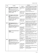
Installation defec-
tiveness on fuser
thermistor 1.
Measure the resistance. If it is
, replace
the fuser unit (see page 1-5-41).
Defective PWB.
Replace the power source PWB or engine
PWB and check for correct operation.
C6040
Fuser heater error
Fuser thermistor 1 detects temperature
change of 20
C/36
F or more for 160
ms 100 times or more since the power is
turned on.
Defective fuser
heater 1.
Check for continuity across each heater. If
none, replace the fuser unit (see page 1-5-
41).
Installation defec-
tiveness on fuser
thermistor 1.
Measure the resistance. If it is
, replace
the fuser unit (see page 1-5-41).
Defective PWB.
Replace the power source PWB or engine
PWB and check for correct operation.
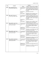
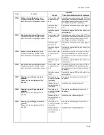
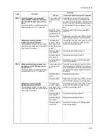
C6050
Abnormally low fuser thermistor 1
temperature
During printing, the temperature at the
heat roller lower than 100
C/212
F is
detected continuously for 1 s.
Defective fuser
heater 1.
Replace the fuser unit (see page 1-5-41).
Defective PWB.
Replace the power source PWB or engine
PWB and check for correct operation.
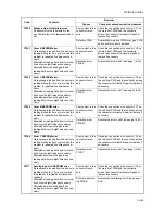
C6100
Fuser heater 2 break
Fuser thermistor 2 detected less than
100
C/212
F for 120 s during driving.
Fuser thermistor 2 deduced less than
150
C/302
F for 300 s during driving.
Fuser thermistor 2 deduced less than
100
C/212
F for 5 s during driving.
Defective fuser
heater 2.
Check for continuity across each heater. If
none, replace the fuser unit (see page 1-5-
41).
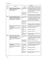
Defective fuser
thermostat 2.
Check for continuity across thermostat. If
none, remove the cause and replace the
fuser unit (see page 1-5-41).
Installation defec-
tiveness on fuser
thermistor 2.
Measure the resistance. If it is
, replace
the fuser unit (see page 1-5-41).
Defective PWB.
Replace the power source PWB or engine
PWB and check for correct operation.
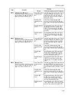
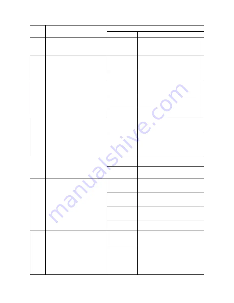
C6120
Abnormally high fuser thermistor 2
temperature
The fuser temperature exceeds 190
C/
374
F for 1 s.
Installation defec-
tiveness on fuser
thermistor 2.
Measure the resistance. If it is
, replace
the fuser unit (see page 1-5-41).
Defective PWB.
Replace the power source PWB or engine
PWB and check for correct operation.
Code
Contents
Remarks
Causes
Check procedures/corrective measures
Summary of Contents for TASKalfa 250ci
Page 4: ...This page is intentionally left blank ...
Page 10: ...This page is intentionally left blank ...
Page 14: ...2JZ 2JX 2JV 2H7 This page is intentionally left blank ...
Page 296: ...2JZ 2JX 2JV 2H7 1 4 78 This page is intentionally left blank ...
Page 348: ...2JZ 2JX 2JV 2H7 1 5 52 This page is intentionally left blank ...
Page 354: ...2JZ 2JX 2JV 2H7 1 6 6 This page is intentionally left blank ...
Page 378: ...2JZ 2JX 2JV 2H7 2 1 24 This page is intentionally left blank ...
Page 388: ...2JZ 2JX 2JV 2H7 2 2 10 This page is intentionally left blank ...
Page 390: ...2JZ 2JX 2JV 2H7 1 2 3 2 Power source PWB ...
Page 395: ...2JZ 2JX 2JV 2H7 1 2 3 7 Engine PWB ...
Page 412: ...2JZ 2JX 2JV 2H7 1 2 3 24 Main PWB ...
Page 430: ...2JZ 2JX 2JV 2H7 1 2 3 42 Feed PWB 40 40 50 40 ppm model Feed PWB 25 25 30 30 ppm model ...
Page 450: ...2JZ 2JX 2JV 2H7 2 4 8 ...
Page 493: ...INSTALLATION GUIDE FOR PAPER FEEDER ...
Page 503: ...INSTALLATION GUIDE FOR 3000 SHEETS PAPER FEEDER ...
Page 558: ...INSTALLATION GUIDE FOR CENTER FOLDING UNIT ...
Page 572: ...INSTALLATION GUIDE FOR MAILBOX ...
Page 580: ...INSTALLATION GUIDE FOR HOLE PUNCH UNIT ...
Page 592: ...INSTALLATION GUIDE FOR JOB SEPARATOR ...
Page 602: ...INSTALLATION GUIDE FOR FAX System ...
Page 619: ...INSTALLATION GUIDE FOR DT 710 ...
Page 622: ...INSTALLATION GUIDE FOR DUCT UNIT ...
Page 625: ......
Page 626: ......


