8
a
b
5
4
3
2
3
1
A
G
G
G
G
G
G
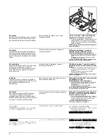
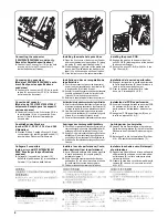
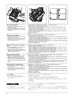
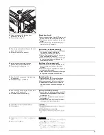
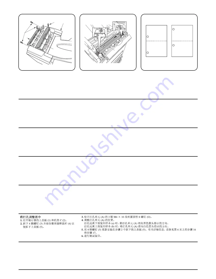
Centering punch-holes
1.
Open the upper cover (1) and the tray C (2)
of the document finisher.
2.
Remove four screws (3) and hold pressing
the finisher releasing lever (4) to remove the
top cover (5).
3.
Loosen two M4 × 10 tap Tight S screws (G) of the hole punch unit (A).
4.
Adjust the position of the hole punch unit (A).
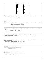
When holes are punched too far lower copy example (a): Slide the hole punch unit (A) to the
direction indicated by the black arrow.
When holes are punched too far upper copy example (b): Slide the hole punch unit (A) to the
direction indicated by the white arrow.
5.
Use four screws (3) to reinstall the top cover (5) which was removed in step 2. For details, see
steps 16 and 17 on page 6.
6.
Perform a test copy.
Centrage des perforations
1.
Ouvrir le capot supérieur (1) et le bac C (2)
du finisseur de document.
2.
Retirer quatre vis (3) et maintenir le levier de
relâchement du finisseur (4) enfoncé pour
retirer le capot supérieur (5).
3.
Desserrer deux vis S taraudées M4 × 10 (G) de la perforatrice (A).
4.
Ajuster la position de la perforatrice (A).
Lorsque les trous sont perforés trop bas dans l’exemple de copie (a): faire glisser la perforatrice
(A) dans la direction indiquée par la flèche noire.
Lorsque les trous sont perforés trop haut dans l’exemple de copie (b): faire glisser la perforatrice
(A) dans la direction indiquée par la flèche blanche.
5.
Utiliser quatre vis (3) pour réinstaller le capot supérieur (5) retiré à l’étape 2. Pour plus de détails,
se reporter aux étapes 16 et 17 de la page 6.
6.
Effectuer une copie de test.
Centrado de los agujeros de perfora-
ción
1.
Abra la cubierta superior (1) y la bandeja C
(2) del finalizador de documentos.
2.
Quite los cuatro tornillos (3) y presione la
palanca de liberación del finalizador (4) para
quitar la cubierta superior (5).
3.
Afloje dos tornillos de ajuste M4 × 10 (G) de la perforadora (A).
4.
Ajuste la posición de la perforadora (A).
Cuando los agujeros hayan sido perforados demasiado hacia abajo en el ejemplo de copia (a):
Deslice la perforadora (A) en el sentido indicado por la flecha negra.
Cuando los agujeros hayan sido perforados demasiado hacia arriba en el ejemplo de copia (b):
Deslice la perforadora (A) en el sentido indicado por la flecha blanca.
5.
Utilice cuatro tornillos (3) para volver a instalar la cubierta superior (5) que fue quitada en el paso
2. Para conocer detalles, consulte los pasos 16 y 17 de la página 6.
6.
Haga una copia de prueba.
Zentrieren der Stanzlöcher
1.
Öffnen Sie die obere Abdeckung (1) sowie
das Fach C (2) des Dokument-Finishers.
2.
Entfernen Sie die vier Schrauben (3) und
drücken Sie den Finisher-Entriegelungshe-
bel (4), um die obere Abdeckung (5) zu ent-
fernen.
3.
Lösen Sie die beiden M4 × 10 Passstift-Verbundschrauben (G) der Lochereinheit (A).
4.
Stellen Sie die Position der Lochereinheit (A) ein.
Wenn die Löcher zu weit unten durchgestanzt werden: Beispiel (a): Schieben Sie die Locherein-
heit (A) in die Richtung des schwarzen Pfeils.
Wenn die Löcher zu weit oben durchgestanzt werden: Beispiel (b): Schieben Sie die Locherein-
heit (A) in die Richtung des weißen Pfeils.
5.
Benutzen Sie die vier Schrauben (3), um die obere Abdeckung (5) anzubringen, die in Schritt 2
entfernt wurde. Nähere Einzelheiten erfahren Sie in den Schritten 16 und 17 auf Seite 6.
6.
Führen Sie eine Testkopie durch.
Centratura dei fori di perforazione
1.
Aprire il pannello superiore (1) e il vassoio C
(2) della finitrice.
2.
Togliere quattro viti (3) e tenere premuta la
leva di rilascio della finitrice (4) per rimuo-
vere il coperchio (5)
3.
Allentare due viti con testa a croce S M4 × 10 (G) dell’unità di perforazione (A).
4.
Regolare la posizione dell’unità di perforazione (A).
Nel caso in cui i fori siano perforati troppo in basso (esempio a): Far scivolare l’unità di perfora-
zione (A) nella direzione indicata dalla freccia nera.
Nel caso in cui i fori siano perforati troppo in alto (esempio b): Far scivolare l’unità di perforazione
(A) nella direzione indicata dalla freccia bianca.
5.
Utilizzare quattro viti (3) per reinstallare il coperchio (5) rimosso nel passo 2. Per dettagli, vedere
passi 16 e 17 a pagina 6.
6.
Eseguire una copia di prova.
パンチ穴のセンター位置調整
1.
ドキュメントフィニッシャの上カバー(1)
と
トレイ C
(2)を開く。
2.
ビス (3)4 本を外し、フィニッシャ解除レ
バー(4) 押しながら天カバー(5) を取り外
す。
3.
パンチユニット (A) のビス M4 × 10 タップタイト S(G)2 本を緩める。
4.
パンチユニット (A) の位置調整を行う。
パンチ穴が下にずれている場合 コピーサンプル (a):パンチユニット (A) を黒矢印の方向へずらす。
パンチ穴が上にずれている場合 コピーサンプル (b):パンチユニット (A) を白矢印の方向へずらす。
5.
手順 2 で外した天カバー(5) をビス (3)4 本で元通り取り付ける。詳細は 6 ページ手順 16、17 を参
照のこと。
6.
テストコピーを行う。
Summary of Contents for TASKalfa 250ci
Page 4: ...This page is intentionally left blank ...
Page 10: ...This page is intentionally left blank ...
Page 14: ...2JZ 2JX 2JV 2H7 This page is intentionally left blank ...
Page 296: ...2JZ 2JX 2JV 2H7 1 4 78 This page is intentionally left blank ...
Page 348: ...2JZ 2JX 2JV 2H7 1 5 52 This page is intentionally left blank ...
Page 354: ...2JZ 2JX 2JV 2H7 1 6 6 This page is intentionally left blank ...
Page 378: ...2JZ 2JX 2JV 2H7 2 1 24 This page is intentionally left blank ...
Page 388: ...2JZ 2JX 2JV 2H7 2 2 10 This page is intentionally left blank ...
Page 390: ...2JZ 2JX 2JV 2H7 1 2 3 2 Power source PWB ...
Page 395: ...2JZ 2JX 2JV 2H7 1 2 3 7 Engine PWB ...
Page 412: ...2JZ 2JX 2JV 2H7 1 2 3 24 Main PWB ...
Page 430: ...2JZ 2JX 2JV 2H7 1 2 3 42 Feed PWB 40 40 50 40 ppm model Feed PWB 25 25 30 30 ppm model ...
Page 450: ...2JZ 2JX 2JV 2H7 2 4 8 ...
Page 493: ...INSTALLATION GUIDE FOR PAPER FEEDER ...
Page 503: ...INSTALLATION GUIDE FOR 3000 SHEETS PAPER FEEDER ...
Page 558: ...INSTALLATION GUIDE FOR CENTER FOLDING UNIT ...
Page 572: ...INSTALLATION GUIDE FOR MAILBOX ...
Page 580: ...INSTALLATION GUIDE FOR HOLE PUNCH UNIT ...
Page 592: ...INSTALLATION GUIDE FOR JOB SEPARATOR ...
Page 602: ...INSTALLATION GUIDE FOR FAX System ...
Page 619: ...INSTALLATION GUIDE FOR DT 710 ...
Page 622: ...INSTALLATION GUIDE FOR DUCT UNIT ...
Page 625: ......
Page 626: ......

