


2KR/2KS
2-1-14
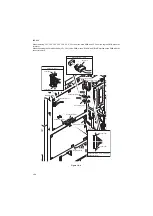
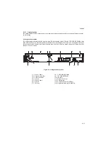
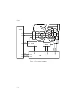
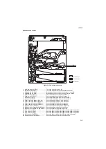
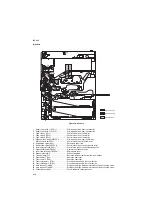
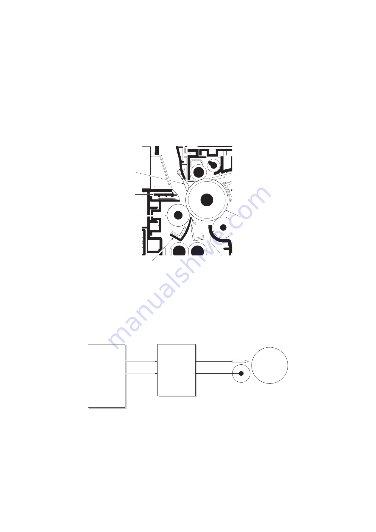
2-1-5 Transfer and separation sections
The transfer and separation section consists mainly of the transfer roller, separation electrode and drum separation claws.
A high voltage generated by the high-voltage PWB (HVPWB) is applied to the transfer roller for transfer charging. Paper
after transfer is separated from the drum by applying separation bias that is output from the high-voltage PWB (HVPWB)
to the separation electrode.
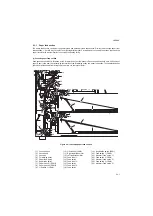
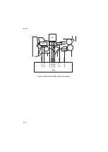
Figure 2-1-14 Transfer and separation sections
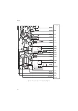
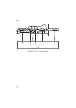
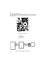
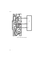
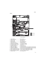
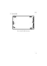
Figure 2-1-15 Transfer and separation sections block diagram
5
1
2
3
4
(1)
Transfer roller
(2)
Transfer guide
(3)
Separation electrode
(4)
Drum separation claws
(5)
Drum
RHVDR
AC HV
TC HV
THVDR
CN1-6
CN1-10
YC13-6
YC13-10
EPWB
HVPWB
Transfer roller
Separation
electrode
Drum
Summary of Contents for TASKalfa 420i
Page 1: ...SERVICE MANUAL Published in May 2010 842KS113 2KSSM063 Rev 3 TASKalfa 420i TASKalfa 520i ...
Page 4: ...This page is intentionally left blank ...
Page 10: ...This page is intentionally left blank ...
Page 14: ...2KR 2KS This page is intentionally left blank ...
Page 224: ...2KR 2KS 1 4 66 This page is intentionally left blank ...
Page 328: ...2KR 2KS 2 3 30 This page is intentionally left blank ...
Page 371: ...INSTALLATION GUIDE FOR PAPER FEEDER ...
Page 381: ...INSTALLATION GUIDE FOR 3000 SHEETS PAPER FEEDER ...
Page 436: ...INSTALLATION GUIDE FOR CENTER FOLDING UNIT ...
Page 450: ...INSTALLATION GUIDE FOR MAILBOX ...
Page 458: ...INSTALLATION GUIDE FOR HOLE PUNCH UNIT ...
Page 470: ...INSTALLATION GUIDE FOR BUILT IN FINISHER ...
Page 483: ...INSTALLATION GUIDE FOR JOB SEPARATOR ...
Page 491: ...INSTALLATION GUIDE FOR FAX System ...
Page 507: ......
Page 508: ......


