background image

SERVICE

MANUAL

Published in August 2009

842KP112

2KPSM062

Rev. 2

TASKalfa 620/820

Summary of Contents for TASKalfa 620

Page 1: ...SERVICE MANUAL Published in August 2009 842KP112 2KPSM062 Rev 2 TASKalfa 620 820 ...

Page 2: ...icials for details in your area for proper disposal ATTENTION IL Y A UN RISQUE D EXPLOSION SI LA BATTERIE EST REMPLACEE PAR UN MODELE DE TYPE INCORRECT METTRE AU REBUT LES BATTERIES UTILISEES SELON LES INSTRUC TIONS DONNEES Il peut être illégal de jeter les batteries dans des eaux d égout municipales Vérifiez avec les fonc tionnaires municipaux de votre région pour les détails concernant des déche...

Page 3: ...laced pages Remarks 1 May 19 2009 1 1 1 1 1 2 1 2 3 1 2 10 1 2 17 1 3 16 1 3 34 1 3 77 1 3 79 to 1 3 81 1 3 83 1 4 8 1 4 9 1 5 6 1 5 12 1 5 14 1 5 18 1 5 21 1 5 24 1 5 41 to 1 5 43 1 5 77 1 5 82 1 6 1 2 4 5 2 August 19 2009 1 3 4 1 3 52 ...

Page 4: ...This page is intentionally left blank ...

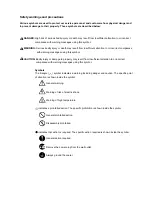
Page 5: ...rsonnel to ensure the safety of their customers their machines as well as themselves during maintenance activities Service personnel are advised to read this booklet carefully to familiarize themselves with the warnings and precautions described here before engaging in maintenance activities ...

Page 6: ... this symbol CAUTION Bodily injury or damage to property may result from insufficient attention to or incorrect compliance with warning messages using this symbol Symbols The triangle symbol indicates a warning including danger and caution The specific point of attention is shown inside the symbol General warning Warning of risk of electric shock Warning of high temperature indicates a prohibited ...

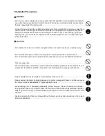
Page 7: ... or dusty place This may cause fire or electric shock Do not install the copier near a radiator heater other heat source or near flammable material This may cause fire Allow sufficient space around the copier to allow the ventilation grills to keep the machine as cool as possible Insufficient ventilation may cause heat buildup and poor copying performance Always handle the machine by the correct l...

Page 8: ... carefully Always check that the copier is correctly connected to an outlet with a ground connection Check that the power cable covering is free of damage Check that the power plug is dust free If it is dirty clean it to remove the risk of fire or electric shock Never attempt to disassemble the optical unit in machines using lasers Leaking laser light may damage eyesight Handle the charger section...

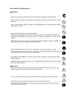
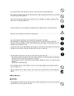
Page 9: ...r trapped wire and missing screws Check that all the caution labels that should be present on the machine according to the instruction handbook are clean and not peeling Replace with new ones if necessary Handle greases and solvents with care by following the instructions below Use only a small amount of solvent at a time being careful not to spill Wipe spills off completely Ventilate the room wel...

Page 10: ...This page is intentionally left blank ...

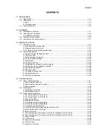
Page 11: ...rts 1 3 104 11 Checking total copy count 1 3 105 12 Refreshing the drum 1 3 105 13 Selecting the language 1 3 105 1 4 Troubleshooting 1 4 1 Paper misfeed detection 1 4 1 1 Paper misfeed indication 1 4 1 2 Paper misfeed detection conditions 1 4 2 3 Paper misfeeds 1 4 10 1 4 2 Self diagnosis 1 4 26 1 Self diagnostic function 1 4 26 2 Self diagnostic codes 1 4 28 1 4 3 Image formation problems 1 4 50...

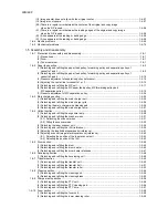
Page 12: ...ger grid 1 5 26 3 Detaching the main charger wire cleaning pad 1 5 26 4 Detaching and refitting the main charger wire 1 5 27 1 5 4 Optical section 1 5 28 1 Detaching and refitting the exposure lamp 1 5 28 2 Detaching and refitting the scanner wires 1 5 31 2 1 Detaching the scanner wires 1 5 31 2 2 Fitting the scanner wires 1 5 33 3 Detaching the laser scanner unit 1 5 36 4 Detaching and refitting ...

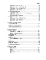
Page 13: ...refitting the ozone filters 1 5 87 1 6 Requirements on PWB Replacement 1 6 1 Upgrading the firmware 1 6 1 1 6 2 Adjustment free variable resistors VR 1 6 2 1 6 3 Remarks on main PWB replacement 1 6 2 1 6 4 Remarks on engine PWB replacement 1 6 3 1 6 5 Remarks on scanner PWB replacement 1 6 3 1 6 6 Upgrading the printer board firmware 1 6 4 1 6 7 Remarks on hard disk unit HDD replacement 1 6 4 2 1 ...

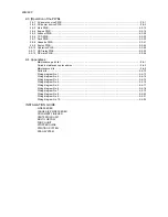
Page 14: ...4 Appendixes Maintenance parts list 2 4 1 Periodic maintenance procedures 2 4 3 Maintenance kits 2 4 9 Parts kits 2 4 10 Wiring diagram No 1 2 4 13 Wiring diagram No 2 2 4 14 Wiring diagram No 3 2 4 15 Wiring diagram No 4 2 4 16 Wiring diagram No 5 2 4 17 Wiring diagram No 6 2 4 18 Wiring diagram No 7 2 4 19 Wiring diagram No 8 2 4 20 Wiring diagram No 9 2 4 21 Wiring diagram No 10 2 4 22 INSTALLA...

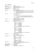
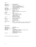
Page 15: ...25 to 200 Includes preset zoom levels Copying speed At 100 magnification in memory copy mode 82 cpm A3 11 x 17 41 sheets min B4 8 1 2 x 14 50 sheets min A4 11 x 8 1 2 82 sheets min A4R 8 1 2 x 11 54 sheets min B5 80 sheets min B5R 58 sheets min When the document processor is used at 100 magnification A4 11 x 8 1 2 82 sheets min 62 cpm A3 11 x 17 31 sheets min B4 8 1 2 x 14 37 sheets min A4 11 x 8 ...

Page 16: ...2000 m 8 202 ft maximum Brightness 1500 lux maximum Dimensions 680 W x 811 D x 1190 H mm 26 3 4 W x 31 15 16 D x46 7 8 H Weight Approx 188 kg Approx 413 6 lbs Space required 1480 mm W x 811 D mm 58 1 4 W x 31 15 16 D Power source 120 V AC 60 Hz 16 0 A 220 240 V AC 50 60 Hz 9 5 A Power consumption 1920 W Options Side feeder Large size side feeder Document finisher Centerfold unit Multi job tray Pun...

Page 17: ...ocument processor DP 4 Cassette 1 5 Cassette 2 6 Cassette 3 7 Cassette 4 8 MP tray multi purpose tray 9 Paper width guides 10 MP tray extension 11 Right cover 12 Handles 13 Main power switch 14 Main power switch cover 15 Document processor bottom cover 16 Original size indicator plates 17 Platen 18 Front cover 19 Output tray option 20 Handles 21 Power cord ...

Page 18: ...aded Indicator 26 Document processor top cover 27 Ejection guide 28 Document processor angle adjustment lever 29 Original eject table 30 Toner container 31 Toner container release lever 32 Paper conveyor 33 Knob A1 34 Lever A2 35 Knob A3 36 Duplex unit 37 Deck conveying unit 38 Paper width guides 39 Paper width adjusting tab 40 Paper length guide 41 Paper length adjusting tab ...

Page 19: ...r 5 Document management key indicator 6 Print management key indicator 7 Repeat copy key indicator 8 Job build key indicator 9 Mixed size originals key indicator 10 System menu counter key 11 Logout key 12 Interrupt key indicator 13 Energy saver key indicator 14 Touch panel 15 Numeric keys 16 Reset key 17 Stop clear key 18 Start key indicator 19 Power key indicator 20 Main power indicator ...

Page 20: ...h Paper and original path 1 Paper feed section 2 Main charging section 3 Optical section 4 Drum section 5 Developing section 6 Transfer section 7 Cleaning section 8 PTC section 9 Fuser section 10 Feedshift and eject section 11 Duplex section 12 Document processor ...

Page 21: ...y an abrupt change in the environmental temperature and cool or hot direct air Avoid places subject to dust and vibrations Choose a surface capable of supporting the weight of the machine Place the machine on a level surface maximum allowance inclination 1 Avoid air borne substances that may adversely affect the machine or degrade the photoconductor such as mer cury acidic of alkaline vapors inorg...

Page 22: ...2KN 2KP 1 2 2 Figure 1 2 1 Installation dimensions a d c e f b 60 30 a 680 mm 26 3 4 b 811 mm 31 15 16 c 1190 mm 46 7 8 d 2148 mm 84 9 16 e 1465 mm 57 11 16 f 1530 mm 60 3 16 ...

Page 23: ...emove the screws Taking out the machine Start Connecting the power cord Initial setting for the developer Make test copies Installing the guide case Attaching the language label 230 V specifications only Remove the tapes of transfer section and duplex unit Installing the toner container Completion of the machine installation ...

Page 24: ...6 Upper left spacer 7 Upper right spacer 8 Upper spacer 9 Supports 10 Outer case 11 Upper case 12 Machine cover 13 DP spacer 14 Deck spacers 15 Cassette spacers 16 Sheet 17 DP sheet 18 Rear sheets 19 Hinge joints 20 Plastic bag 21 Operation guide 22 Casette size plates 23 Labels 24 Cursor pins 25 Bar code labels 26 Plastic bag 27 Guide case 28 Spacer ...

Page 25: ... upper left spacer the upper right spacer the outer case and the supports 2 Cut four tapes of the skid each corner 3 Cut each tape which locks the slope and the spacer 4 Rotate slopes as shown in the figure and make them for machine sliding Finally check that there is no level differ ence in slopes circle section of figure 1 2 3 Figure 1 2 3 Taking out the machine Slopes ...

Page 26: ...cover and pull out the handles on machine left and right 6 Lift the machine each left and right one side and then remove the lower left and right spacers 7 Move the machine alongside slopes to slide to the floor Figure 1 2 4 Slope Slope ...

Page 27: ...ve four tapes and three pins Figure 1 2 6 Remove the tapes pins spacers and sheet Tapes Tapes Tape Tape Tape Tape Tapes Tapes Tape Tape Tape Tapes Tapes Tapes DP spacer DP sheet Pin for light source unit 1 Pin for light source unit 1 Tape Tape Tape Tape Pin for light source unit 2 ...

Page 28: ...ecifications Remove the tape of power cord Figure 1 2 7 4 Remove four tapes and two rear sheets Figure 1 2 8 5 Open the DP and then remove three tapes and sheet Figure 1 2 9 Tapes 120 V specifications 230 V specifications Tape Tapes Tape Tape Rear sheet Rear sheet Tapes Tape Sheet ...

Page 29: ...o deck spacers 7 Remove the tape from the deck spacer of cassette 1 and then remove the guide case Figure 1 2 10 8 Pull out cassette 3 and 4 then remove two cassette spacers and tapes Figure 1 2 11 Deck spacer Guide case Tape Deck spacer Cassette spacer Tape ...

Page 30: ...onveying unit 2 Remove the tape from the transfer section 3 Refit the paper conveying unit 4 Pull out the duplex unit 5 Remove the two tapes 6 Refit the duplex unit Figure 1 2 13 Remove the screws Screws Remove the tapes of transfer section and duplex unit Tape Paper conveying unit Tapes Duplex unit ...

Page 31: ...st ten times to dis tribute the toner evenly 5 Turn the toner container upside down and shake it vertically at least ten times 6 Hold the toner container horizontally and shake it from side to side at least five times 7 Turn the toner container upside down and shake it from side to side at least five times Do not install the toner container before shaking it sufficiently This may cause errors due ...

Page 32: ...t will count up from 0 and will become an instal lation end by 180 RESULT Result of the installation 0 During installation 1 Installation is successful 2 Installation is failed If the installation is failed enter 001 using the numeric keys and press the start key to exit the maintenance mode When Reinstall the toner container is displayed pull out the container and tap and shake the container to a...

Page 33: ... deck front cursors appropriately and tighten the screws if the clearance between the paper and deck front cursors is tight When fixing the paper width guides posi tion of cassette 3 or 4 use cursor pins sup plied with the machine 2 Make test copies Figure 1 2 17 Make test copies Screw Hole Deck front cursor Deck front cursor Deck front cursor Cursor pins Cursor pins Paper width guides ...

Page 34: ...attach the correspond language of operation unit label MP label DP labels and main power switch label Figure 1 2 18 Figure 1 2 19 Attaching the language label 230 V specifications only MP label DP labels DP label Main power switch label ...

Page 35: ...2KN 2KP 1 2 15 1 Attach the guide case to the machine right Figure 1 2 20 Installing the guide case Guide case Completion of the machine installation ...

Page 36: ... Month Year metric specifications U277 Setting auto application change time 30 s U281 Setting stamp mode ON OFF OFF U326 Setting the black line cleaning indication ON 8 U327 Setting the drawer heater ON OFF Drawer heater OFF Side feeder dehumidifier heater OFF U330 Setting the number of sheets to enter stacking mode during sort operation 201 U331 Switching the paper ejection mode Face up ejection ...

Page 37: ... Five 5 M4 x 6 chrome TP screws P N B4A04060 Two 2 M4 x 10 chrome TP screws P N B4A04100 Before installing the key counter press the Power key on the operation panel to off Make sure that the Power lamp is off before turning off the main power switch And then unplug the power cable from the wall outlet Turning off the main power switch before pressing the Power key to off may cause damage to the e...

Page 38: ...nserted to the key counter cover retainer on the machine using the screw Figure 1 2 22 8 Insert the key counter into the key counter socket assembly 9 Connect the power cord and turn the main power switch on and 10 Enter the maintenance mode to run mainte nance item U204 and select KEY COUNTER 11 Exit the maintenance mode 12 Check that the message requesting the key counter to be inserted is displ...

Page 39: ...ric keys Enter 001 using the cursor up down keys or numeric keys and press the start key Enter the maintenance item number using the cursor up down keys or numeric keys The selected maintenance item is run Press the stop clear key Press the start key Start End Maintenance mode is entered The maintenance item is selected Maintenance mode is exited Repeat the same maintenance item Run another mainte...

Page 40: ...rinting area for folio paper Length Width 330 210 1 U037 Checking the operation of the fan motors U051 Adjusting the amount of slack in the paper Plain paper Thick paper 3 3 3 3 3 3 1 0 0 0 0 0 0 1 U052 Adjusting duplex 6 1 U053 Setting the adjustment of the motor speed Interlock setting MAIN MOTOR POLYGON MOTOR Separate setting Thick paper setting Transfer setting 7 10 3 8 8 1 6 1 7 10 3 8 6 8 1 ...

Page 41: ... main charger 5 1 2 OFF 1 2 U103 Setting the surface potential 0 1 U110 Checking the drum count U111 Checking clearing the drum drive time 0 1 2 U127 Checking clearing the transfer belt count U129 Adjusting the transfer timing Transfer charging output ON timing for plain paper Transfer charging output OFF timing for plain paper Transfer charging output ON timing for thin paper Transfer charging ou...

Page 42: ...S host monitoring system U203 Operating the DP separately U204 Setting the presence or absence of a key card or key counter OFF 1 U206 Setting the presence or absence of the coin vender OFF 1 2 U207 Checking the keys on the operation panel U208 Setting the paper size for the feeders 11 x 8 5 inch A4 metric 1 2 U212 Setting the feeder lift operation SIDE FEED 1 2 U233 Checking the operation of the ...

Page 43: ...0 1 2 U335 Setting the drum heater mode ON1 1 2 U339 Setting the drum heater ON OFF OFF 1 U341 Specific paper feed location setting for printing func tion U342 Setting the ejection restriction ON 1 2 U343 Switching between duplex simplex copy mode OFF 1 2 U344 Setting the low power mode Energy star 120 V 1 2 GEEA 220 240 V 1 2 U345 Setting the value for maintenance due indication Image processing ...

Page 44: ...U922 Checking clearing the solenoid count value U925 Checking clearing the system error counts U927 Clearing the all copy counts and machine life counts U928 Checking machine life counts U935 Relay board maintenance MODE 0 1 U954 Setting the type of cooling fan MODE2 1 U965 Setting the cassette disconnection OFF 1 U984 Checking the developing unit number U985 Displaying the developing unit history...

Page 45: ...er feed loca tion When output is complete the screen for selecting an item is displayed Completion Press the stop clear key at the screen for selecting an item The screen for selecting a maintenance item No is displayed U001 Exiting the maintenance mode Description Exits the maintenance mode and returns to the normal copy mode Purpose To exit the maintenance mode Method Press the start key The nor...

Page 46: ...rsor press Left or Right in the bottom row 2 Press the start key The telephone number is set and the screen for selecting a maintenance item No is displayed Completion To exit this maintenance item without changing the current setting press the stop clear key The screen for selecting a maintenance item No is displayed U004 Setting the machine number Description Sets or displays the machine number ...

Page 47: ...n starts Copy operation is simulated without paper under the set conditions When operation is complete the screen for selecting an item is displayed 6 To stop continuous operation press the stop clear key Completion Press the stop clear key at the screen for selecting an item The screen for selecting a maintenance item No is displayed U018 Displaying the ROM checksum Description Displays the check...

Page 48: ...ch panel It is displayed in reverse 3 Press the start key All data in the backup memory is initialized and the default setting for the inch spec ifications is registered When initializing is complete the machine automatically returns to the same sta tus as when the main power switch is turned on Completion To exit this maintenance item without executing initialization press the stop clear key The ...

Page 49: ...tting 1 Select the item to initialize 2 Press EXECUTE on the touch panel It is displayed in reverse 3 Press the start key Backup data is initialized When initializing is complete the machine automatically returns to the same status as when the main power switch is turned on Completion To exit this maintenance item without executing initialization press the stop clear key The screen for selecting a...

Page 50: ...cription Transfers the backup data of the EEPROM which was transferred with the U026 to flash memory Purpose To use after the main PWB replaced Method 1 Press the start key The screen for executing is displayed 2 Press EXECUTE on the touch panel It is displayed in reverse 3 3 Press the start key to transfer the backup data The screen displays the result EXECUTE CHECK SUM CODE XXXX Where XXX is the...

Page 51: ...rned reversing ON high speed PF MOT3 H Paper feed motor 3 PFM3 is turned ON high speed PF MOT4 H Paper feed motor 4 PFM4 is turned ON high speed VF MOT H The vertical feed motor VFDM is turned ON high speed PF MOT1 Paper feed motor 1 PFM1 is turned forwarding ON PF MOT2 Paper feed motor 2 PFM2 is turned ON DECK FD MOT Paper feed motor 1 PFM1 is turned reversing ON DUP SB MOT The duplex switchback ...

Page 52: ...witch ESW FEED B SW D Feed switch 2 FSW2 LCF SW A Deck conveying switch 2 DKCSW2 LCF SW B Deck conveying switch 1 DKCSW1 FEED C SW Feed switch 3 FSW3 FEED D SW Feed switch 4 FSW4 FEED E SW Feed switch 5 FSW5 LDECK FD SW Side feeder feed switch SFFSW FS SW Feedshift switch FSSW DUP JAM SW Duplex jam detection switch DUPJSW DUP FEED SW Duplex feed switch DUPFSW DUP CV SW A Duplex conveying switch 1 ...

Page 53: ...ting an item is displayed 2 Select CASSETTE or BYPASS MP tray on the touch panel 3 Select the item to be adjusted CASSETTE BYPASS Maintenance item No Description Display Solenoid MP SOL MP solenoid MPSOL FS SOL Feedshift solenoid FSSOL WEB SOL Fuser web solenoid FWSOL DUP FS SOL Duplex feedshift solenoid DUPFSSOL DUP SB SOL Duplex switchback solenoid DUPSBSOL Display Description Setting range Init...

Page 54: ... key to output a test pattern 3 Change the setting value using the cursor up down keys For output example 1 decrease the value For output example 2 increase the value Figure 1 3 2 4 Press the start key The value is set Caution Check the copy image after the adjustment If the image is still incorrect perform the following adjustments in maintenance mode Completion Press the stop clear key at the sc...

Page 55: ...splayed 2 Select the item to operate The selected item is displayed in reverse and starts driving the fan motor 3 To stop the motor press the stop clear key Completion Press the stop clear key when the motor stops The screen for selecting a maintenance item No is displayed Maintenance item No Description Display Setting Setting range Initial setting LENGTH DATA Length 330 to 356 mm 330 WIDTH DATA ...

Page 56: ...Press the start key The value is set Completion Press the stop clear key at the screen for selecting an item The screen for selecting a maintenance item No is displayed Maintenance item No Description Display Description Setting range Initial setting Change in value per step LOW SPEED DATA Amount of slack at the registration roller for low speed conveying 120 0 to 120 0 3 0 6 mm HIGH SPEED DATA Am...

Page 57: ...sing the value makes narrower 3 Press the start key The value is set 4 Press the interrupt key 5 Press the start key to output the test pattern 6 Open the front cover 7 Pull the duplex unit out and check the position of duplex side registration guide Completion Press the stop clear key at the screen for selecting an item The screen for selecting a maintenance item No is displayed Maintenance item ...

Page 58: ...or and feed motor are change at the same time 4 Press the start key The value is set Interrupt copy mode While this maintenance item is being executed a VTC pattern shown below is output in interrupt copy mode Correct values for an A3 11 x 17 output are A 400 0 5 mm B 270 0 5 mm Adjustment 1 Output an A3 11 x 17 VTC pattern in interrupt mode 2 Measure A and B on the VTC pattern Figure 1 4 1 and pe...

Page 59: ... 3 When the faulty transfer occurs periodically sample 2 press the numerical key of Band Cycle to decrease the setting value 4 Press the start key The value is set Completion Press the stop clear key at the screen for selecting an item The screen for selecting a maintenance item No is displayed Maintenance item No Description Display Description Setting range Default setting MAIN MOTOR Drive motor...

Page 60: ... fan motor for certain period of time to prevent rise in temperature inside the machine in sleep mode In default setting the fan motor stops immediately when switched to sleep mode and too high temper ature is detected inside the machine Method Press the start key The screen for executing is displayed Setting 1 Select ON or OFF The selected item is displayed in reverse Initial setting OFF 2 Press ...

Page 61: ...r selecting an item The screen for selecting a maintenance item No is displayed Caution The following settings are also reset to the initial values by performing this maintenance item Exposure density gradient set in maintenance mode U093 Exposure set in the copy default item of the copier management mode U061 Checking the operation of the exposure lamps Description Lights the exposure lamps Purpo...

Page 62: ... from an original is available in the interrupt copying mode Completion Press the stop clear key at the screen for adjustment The screen for selecting a maintenance item No is dis played U064 Adjusting the CCD level Description Adjusts the CCD level Purpose To adjust when density difference due to CCD is generated between both sides of the center of the copy image Setting 1 Press the start key The...

Page 63: ... 1 3 6 4 Press the start key The value is set Adjustment Auxiliary scanning direction 1 Press the interrupt key 2 Place an original and press the start key to make a test copy 3 Change the setting value using the cursor up down keys For copy example 1 increase the value For copy example 2 decrease the value Figure 1 3 7 4 Press the start key The value is set Completion Press the stop clear key at ...

Page 64: ...crease the value For copy example 2 decrease the value Figure 1 3 8 6 Press the start key The value is set Caution Check the copy image after the adjustment If the image is still incorrect perform the following adjustments in maintenance mode Completion Press the stop clear key at the screen for selecting an item The screen for selecting a maintenance item No is displayed Maintenance item No Descr...

Page 65: ...ample 1 decrease the value For copy example 2 increase the value Figure 1 3 9 6 Press the start key The value is set Caution Check the copy image after the adjustment If the image is still incorrect perform the following adjustments in maintenance mode Completion Press the stop clear key at the screen for selecting an item The screen for selecting a maintenance item No is displayed Maintenance ite...

Page 66: ...s to the left when the setting value is decreased 3 Press the start key The value is set 4 Select TEST POSITION of the screen for selecting an item 5 Select the Scanning position using the cursor up down keys 6 Press the start key The value is set 7 Set the original the one which density is known in the document processor and press the interrupt key The screen for the test copy mode is displayed 8...

Page 67: ... Figure 1 3 10 6 Press the start key The value is set Caution Check the copy image after the adjustment If the image is still incorrect perform the following adjustments in maintenance mode Completion Press the stop clear key at the screen for selecting an item The screen for selecting a maintenance item No is displayed Maintenance item No Description Display Description Setting range Initial sett...

Page 68: ...ress the start key The value is set Adjustment Trailing edge registration 1 Press the interrupt key 2 Place an original on the DP and press the start key to make a test copy 3 Change the setting value using the cursor up down keys For copy example 1 increase the value For copy example 2 decrease the value Figure 1 3 12 4 Press the start key The value is set Maintenance item No Description Display ...

Page 69: ...n the DP and press the start key to make a test copy 5 Change the setting value using the cursor up down keys For copy example 1 increase the value For copy example 2 decrease the value Figure 1 3 13 6 Press the start key The value is set Caution Check the copy image after the adjustment If the image is still incorrect perform the following adjustments in maintenance mode Completion Press the stop...

Page 70: ...under the selected conditions 5 To stop operation press the stop clear key Completion Press the stop clear key with the scanning operation stopped The screen for selecting a maintenance item No is displayed Maintenance item No Description Display Operation SCANNER MOT Scanner operation HOME POTION Home position operation DP READING DP scanning position operation DUST CHECK Dust adhesion check oper...

Page 71: ... executing is displayed Setting 1 Change the setting using the cursor up down keys Increasing the setting makes the luminosity higher and decreasing it makes the luminosity lower 2 Press the start key The value is set Supplement While this maintenance item is being executed copying from an original is available in the interrupt copying mode Completion Press the stop clear key The screen for select...

Page 72: ... occurs during auto adjustment DATA XX XX is replaced by an error code is displayed and operation stops Should this happen determine the details of the problem and either repeat the pro cedure from the beginning or adjust the remaining items manually by running the corresponding main tenance items Completion Press the stop clear key after auto adjustment is complete The screen for selecting a main...

Page 73: ...paring the scan data of the original trailing edge and that taken after the original is conveyed past the DP original scanning position If dust is identified the DP original scanning position is adjusted for the following originals Purpose When using DP to solve the problem when black lines occurs due to the dust with respect to original reading position Method Press the start key The screen for s...

Page 74: ...etting 4 Press the interrupt key The copy mode screen is displayed 5 Press the start key A MIP PG pattern is output Completion Press the stop clear key The screen for selecting a maintenance item No is displayed Maintenance item No Description Display PG pattern to be output Purpose GRAYSCALE To check the laser scanner unit engine output characteristics MONO LEVEL To check the drum quality 256 LEV...

Page 75: ...displayed and operation stops Should this happen determine the details of the problem and either repeat the pro cedure from the beginning or adjust the remaining items manually by running the corresponding main tenance items Since the scanner magnification in the main direction is not automatically adjusted use U065 for this adjustment Completion Press the stop clear key after auto adjustment is c...

Page 76: ...o return to the screen for selecting an item press the stop clear key Setting Gradient in text mode 1 Select the item to be set The selected item is displayed in reverse 2 Change the setting value using the cursor up down keys Increasing the setting makes the change in density larger and decreasing it makes the change smaller 3 Press the start key The value is set 4 To return to the screen for sel...

Page 77: ...e screen for selecting an item press the stop clear key Supplement While this maintenance item is being executed copying from an original is available in the interrupt copying mode Completion Press the stop clear key at the screen for selecting an item The screen for selecting a maintenance item No is displayed Maintenance item No Description Display Setting Setting range Initial set ting PHOTO DA...

Page 78: ...nt Method to set the original size judgment time 1 Adjust the preset value using the or keys A larger value increases the original size judgment time and a smaller value decreases it 2 Press the start key The value is set 3 To return to the screen for selecting an item press the stop clear key Completion Press the stop clear key at the screen for selecting an item The screen for maintenance item N...

Page 79: ...ue when poor image quality is caused by dirt in the main charger wire 3 Press the start key The value is set Setting the potential compensation of first copy start 1 Select START ADJ GAIN at the screen for selecting an item 2 Select 0 OFF or 1 ON using the or keys Initial setting 0 OFF 3 Press the start key The value is set Supplement When MC ON OFF or LASER ON OFF is selected copying from an orig...

Page 80: ...EST at the screen for selecting an item 2 Press the start key Drive motor transfer motor and developing motor are turned on and then cleaning lamp and PTC unit is turned on Supplement While this maintenance item is being executed copying from an original is available in the interrupt copying mode Completion Press the stop clear key at the screen for selecting an item The screen for maintenance ite...

Page 81: ...copier stops copying temporarily and starts charger cleaning operation If OFF is selected when the preset number of sheets for charger cleaning operation is exceeded during copying the copier continues copying to the end and then starts charger cleaning operation 3 Press the start key The value is set Completion Press the stop clear key The screen for selecting a maintenance item No is displayed U...

Page 82: ...electing a maintenance item No is dis played Setting 1 Enter a five digit drive time using the numeric keys 2 Press the start key The drive time is set and the screen for selecting a maintenance item No is dis played Completion To exit the maintenance mode without changing the drive time press the stop clear key The screen for selecting a maintenance item No is displayed U127 Checking clearing the...

Page 83: ... Press the start key The screen for executing is displayed 2 Press the start key Installation of the toner is started Approximately 5 minutes When it becomes 3 minutes before an installation end it will count up from 0 and will become an instal lation end by 180 Completion Press the stop clear key after initial setting is complete The screen for selecting a maintenance item No is displayed Mainten...

Page 84: ...d 1 Press the start key The screen for executing is displayed 2 Press TONER MOT on the touch panel It is displayed in reverse and the operation starts 3 To stop the operation press the stop clear key Completion Press the stop clear key after operation stops The screen for selecting a maintenance item No is displayed U137 Checking the toner level detection sensor Description Displays the detection ...

Page 85: ...of every 10k after it In accordance with the average print coverage ratio of 500 toner placing width of the execution time of T7 control is decided Method Toner applying operation quantity for intermittent copying 1 Select INTERVAL2 at the screen for selecting an item 2 Change the setting using the cursor up down keys Initial setting 500 3 Press the start key The setting is set Maintenance item No...

Page 86: ... To discontinue output once execution of T7 control 1 2 3 100 sheet output 500 sheet output 500 sheets Previous T7 control 400 sheet output 600 sheet output 1200 sheet output 200 sheet output 300 sheet output Once interrupted and toner appying operation by 500 sheets Once interrupted and toner appying operation by 500 sheets Once interrupted and toner appying operation by 500 sheets 500 sheets Pre...

Page 87: ...nce when correcting the toner control Purpose To check the developing drive time after replacing the developing unit Method Press the start key The developing drive time is displayed in minutes Completion Press the stop clear key The screen for selecting a maintenance item No is displayed U158 Checking the developing count Description Displays the developing count for checking Purpose To check the...

Page 88: ...m No is displayed Maintenance item No Description Display Description PAGE1 Control temperature during copying primary stabilization fuser temperature sec ondary stabilization fuser temperature aging time after secondary stabilization control temperature adjustment in duplex copying and time from power on to stabi lization of fusing PAGE2 Control temperature adjustment in duplex copying using A4 L...

Page 89: ...cating a problem in the fuser section Purpose To prevent accidents due to an abnormally high fuser temperature Method 1 Press the start key The screen for executing is displayed 2 Press EXECUTE on the touch panel 3 Press the start key The detection of a service call code is cleared Completion Press the stop clear key The screen for selecting a maintenance item No is displayed U167 Checking clearin...

Page 90: ...g a maintenance item No is displayed U194 Setting the fuser web drive Description Sets the interval number of copies for turning on the fuser web solenoid Purpose To be executed when the fuser web roller becomes extremely soiled Method Press the start key The screen for adjustment is displayed Setting 1 Select the item to be set 2 Change the setting using the cursor up down keys When setting to th...

Page 91: ...his maintenance item without changing the current setting press the stop clear key The screen for selecting a maintenance item No is displayed U199 Displaying fuser heater temperature Description Displays the detected fuser temperature temperature and humidity outside the machine and temperature and humidity inside the machine Purpose To check the fuser temperature temperature and humidity outside...

Page 92: ... selecting a maintenance mode No is displayed U202 Setting the KMAS host monitoring system Description Initializes or operates the KMAS host monitoring system This is an optional device which is currently supported only by Japanese specification machines so no setting is necessary U203 Operating DP separately Description Simulates the original conveying operation separately in the DP Purpose To ch...

Page 93: ...currently supported only by Japanese specification machines so no setting is necessary U207 Checking the operation panel keys Description Checks operation of the operation panel keys Purpose To check operation of all the keys and LEDs on the operation panel Method 1 Press the start key The screen for executing is displayed 2 COUNT1 is displayed and the leftmost LED on the operation panel lights 3 ...

Page 94: ...A3 A4 or A4R Initial setting A4 220 240 V specifications 8 5 x 11 120 V specifications 4 Press the start key The setting is set Completion To exit this maintenance item without changing the current setting press the stop clear key The screen for selecting a maintenance item No is displayed U212 Setting the feeder lift operation Description Sets the operation of the side feeder lift motor for when ...

Page 95: ...ine Method Press the start key The screen for selecting an item is displayed Setting 1 Select the destination Initial setting NOTHING 2 Press the start key The setting is set Completion Press the stop clear key The screen for selecting a maintenance item No is displayed Maintenance item No Description Display Switches FEED SW1 Side feeder feed switch 1 SFFSW1 FEED SW2 Side feeder feed switch 2 SFF...

Page 96: ...ng a maintenance item No is displayed U237 Adjusting finisher stack quantity Description Sets the number of sheets of stack on the main tray in the optional document finisher Purpose To change the setting when a stack malfunction has occurred Method Press the start key The screen for selecting an item is displayed Setting 1 Change the setting using the cursor up down keys Initial setting 0 If the ...

Page 97: ...r paper conveying belt motor PCBM L is turned on LGR_TEST Front rear upper side registration guide motor SRGM FU RU test operation for 11 x 17 size A3_TEST Front rear upper side registration guide motor SRGM FU RU test operation for A3 size WDTH_MT_L Lower side registration guide motor SRGM L is turned on SLAP_MT_INI Movable guide motor MGM is turned on initial driving SLAP_MT_MOV Movable guide mo...

Page 98: ...he document finisher Method 1 Press the start key The screen for selecting an item is displayed 2 Turn each switch ON manually When a switch is detected to be in the ON position the display for that switch will be highlighted 3 Change the screen using the or keys Maintenance item No Description Display Motors and solenoids SDL_MT_H Main motor MM is turned ON high speed SDL_MT_L Main motor MM is tu...

Page 99: ...Y_LM_SW Main tray upper limit detection sensor MTULDS 1000_SW Main tray load 1000 detection sensor MTLDS 10 1500_SW Main tray load 1500 detection sensor MTLDS 15 JTRAY_LLT_SW Multi job tray lower limit detection sensor MJTLLDS 3000_SW Main tray load 3000 detection sensors MTLDS 30 MTRAY_LLT_SW Main tray lower limit detection sensor MTLLDS N_STP_HP_SW N_STP_CT_SW W_UF_HP_SW Front upper side registr...

Page 100: ...s of a switch is detected the corresponding switch is displayed in reverse A check on the ON OFF state of the original length size switch OLSW is possible only when the original set switch OSSW is ON Completion Press the stop clear key The screen for selecting a maintenance item No is displayed Maintenance item No Description Display Operation DP FEED MOT Original feed motor OFM is turned ON forwa...

Page 101: ...M operation set the paper to the side feeder The selected item is displayed Side feeder Large size side feeder 3 To stop operation press the stop clear key If this maintenance item is executed with the upper cover of the side feeder open detection of the upper limit is not possible and thus the side feeder lift motor overruns Completion Press the stop key after operation stops The screen for selec...

Page 102: ... position is not proper Setting the punch limit Sets the maximum number of punches possible in order to be informed of the timing for disposing of waste punch Decrease the value when using thick paper frequently Start Press the start key The screen for selecting an item is displayed Setting the registration stop timing in punch mode 1 Select PUNCH REGIST ADJUST at the screen for selecting an item ...

Page 103: ... 1 Select SADDLE STAPLE ADJUST at the screen for selecting an item 2 Select the size to be set 3 Change the setting using the cursor up down keys If the staple position is displaced toward the ejection side copy sample 1 decrease the preset value If the staple position is displaced toward the feeding side copy sample 2 increase the preset value Maintenance item No Description Description Setting r...

Page 104: ...stop clear key Maintenance item No Description Copy sample 1 Copy sample 2 Display Description Setting range Initial set ting Change in value A4R 8 5 x 11 Adjustment of center folding position for A4R 8 5 x 11 size 10 to 10 0 0 55 mm B4R 8 5 x 14 Adjustment of center folding position for B4R 8 5 x 14 size 10 to 10 0 0 55 mm A3R 11 x 17 Adjustment of center folding position for A3R 11 x 17 size 10 ...

Page 105: ...maintenance item No is displayed Completion To exit this maintenance item without changing the current setting press the stop clear key The screen for selecting a maintenance item No is displayed U251 Checking clearing the maintenance count Description Displays clears and changes the maintenance count Purpose To check the maintenance count Also to clear the count during maintenance service Method ...

Page 106: ... displayed Supplement The specified initial settings are provided according to the destinations in the maintenance items below To change the initial settings in those items be sure to run maintenance item U021 after changing the destina tion Initial setting according to the destinations Maintenance item No Description Display Description JAPAN METRIC Metric Japan specifications INCH Inch North Ame...

Page 107: ...ning auto start function ON OFF Description Selects if the auto start function is turned on Purpose Normally no change is necessary According to user request changes the setting Method Press the start key The screen for selecting an item is displayed Setting 1 Select either ON or OFF The selected item is displayed in reverse Initial setting ON 2 Press the start key The setting is set and the scree...

Page 108: ...er request If a paper jam occurs frequently in the optional document finisher when the number of copies is counted at the time of paper ejection copies are provided without copy counts The copy service provider cannot charge for such copying To prevent this the copy timing should be made earlier If a paper jam occurs frequently in the paper conveying or fuser sections when the number of copies is ...

Page 109: ...iption Selects year month and day as the order of that appears on lists etc Purpose Set according to the user preference Method Press the start key The screen for selecting an item is displayed Setting 1 Select the desired order The selected item is displayed in reverse Initial setting MONTH DATE YEAR for the inch specifications DATE MONTH YEAR for the metric specifications 2 Press the start key T...

Page 110: ... the start key The value is set and the screen for selecting a maintenance item No is displayed Completion To exit this maintenance item without changing the current setting press the stop clear key The screen for selecting a maintenance item No is displayed U277 Setting auto application change time Description Sets the time that passes until the machine starts automatically printing after complet...

Page 111: ...unt value is displayed only if the setting is ON 2 Press the start key The setting is set and the screen for selecting a maintenance item No is displayed Setting the count value 1 Enter a three digit value using the or key or numeric keys and then press the start key The value is set The setting value x 1000 sheet is possible for a display setting count value When reading a display setting count v...

Page 112: ...rom the optional document finisher s sub tray to its main tray when sorting is turned ON in the setting for the output mode under user simulation Purpose To be set as required according to the number of copies the user makes Method Press the start key The current setting is displayed Setting 1 Change the setting using the cursor up down keys 2 Press the start key The value is set and the screen fo...

Page 113: ...ze The coefficient set here is used to convert the black ratio in relation to the A4 11 x 8 1 2 size and to display the result in user simulation Purpose To set the coefficient for converting the black ratio for nonstandard sizes in relation to the A4 11 x 8 1 2 size for copying and printing respectively Method Press the start key The screen for selecting an item is displayed Setting 1 Select copy...

Page 114: ...um heater ON OFF Description Sets the drum heater and drawer heater to ON or OFF for the sleep mode Purpose To change the setting when dew condensation on the drum is heavy Method Press the start key The screen for selecting an item is displayed Setting 1 Select ON or OFF Initial setting OFF When setting is turned to ON the setting of U327 is turned as ON and U335 is turned as ON1 or ON2 2 Press t...

Page 115: ...od 1 Press the start key The screen for selecting an item is displayed 2 Select ON or OFF Initial setting ON 3 Press the start key The setting is set Completion To exit this maintenance item without changing the current setting press the stop clear key The screen for selecting a maintenance item No is displayed U343 Switching between duplex simplex copy mode Description Switches the initial settin...

Page 116: ... item No is displayed U345 Setting the value for maintenance due indication Description Sets when to display a message notifying that the time for maintenance is about to be reached by setting the number of copies that can be made before the current maintenance cycle ends When the difference between the number of copies of the maintenance cycle and that of the maintenance count reaches the set val...

Page 117: ... the image is still incorrect perform the following adjustments in maintenance mode Completion Press the stop clear key at the screen for selecting an item The screen for selecting a maintenance item No is displayed Maintenance item No Description Display Description Setting range Initial setting Change in value per step LEAD Printer leading edge margin 0 0 to 10 0 3 0 0 1 mm A Printer left margin...

Page 118: ... start key The value is set Caution Check the copy image after the adjustment If the image is still incorrect perform the following adjustments in maintenance mode Completion Press the stop clear key at the screen for selecting an item The screen for selecting a maintenance item No is displayed Maintenance item No Description Display Description Setting range Initial setting Change in value per st...

Page 119: ...wer Figure 1 3 18 6 Press the start key The value is set Completion Press the stop clear key at the screen for selecting an item The screen for selecting a maintenance item No is displayed Maintenance item No Description U403 P 1 3 80 U402 P 1 3 79 U404 Display Description Setting range Initial setting Change in value per step A MARGIN Left margin front 0 0 to 10 0 1 0 0 1 mm B MARGIN Leading edge...

Page 120: ...ress the interrupt key 3 Place an original and press the start key to make a test copy 4 Change the setting value using the cursor up down keys For copy example 1 decrease the value For copy example 2 increase the value Figure 1 3 19 5 Press the start key The value is set Completion Press the stop clear key at the screen for selecting an item The screen for selecting a maintenance item No is displ...

Page 121: ...put position Description Adjust the writing position of a laser output Purpose Enter the numerical value indicated by the LSU cover in order to arrange the writing position of three laser when replacing the laser scanner unit Method Press the start key The screen for executing is displayed Setting 1 Select the item to be adjusted 2 Change the setting using the cursor up down keys 3 Press the start...

Page 122: ...yed Completion To exit this maintenance item without changing the current setting press the stop clear key The screen for selecting a maintenance item No is displayed U506 Setting the time out Description Sets the communication timeout time for connection to a computer Purpose To change the preset value if a communication error occurs after connection to a computer continues for a long time By del...

Page 123: ...ether or not the enterprise mode setting is enabled if an optional network scanner is installed Purpose According to user request changes the setting Supplement It is not possible to turn setting simultaneously with U511 Setting scan To FTP or U512 Setting scan to SMB to ON Method Press the start key The screen for selecting an item is displayed Setting 1 Select ON or OFF The selected item is disp...

Page 124: ...d U512 Setting scan To SMB Description Sets whether or not scan to SMB setting is enabled if an optional network scanner is installed Purpose According to user request changes the setting Supplement It is not possible to turn setting simultaneously with U510 Setting the enterprise mode to ON Method Press the start key The screen for selecting an item is displayed Setting 1 Select ON or OFF The sel...

Page 125: ...s Purpose To check the paper jam status Also to clear the jam counts after replacing consumable parts Start Press the start key The screen for selecting an item is displayed Method Displays clears the jam counts 1 Select COUNT at the screen for selecting an item The count for jam detection by type is displayed 2 Change the screen using the or keys Select the counts for all jam codes and press the ...

Page 126: ...he counts for all service call press the reset key and then press the start key The count is cleared Method Displays the total call for service counts 1 Select TOTAL COUNT in the screen for selecting an item The total number of call for service counts by type is displayed 2 Change the screen using the or keys The total number of call for service count cannot be cleared To return to the screen for ...

Page 127: ... partial operation control Description Resets the service call code for partial operation control Purpose To be reset after partial operation is performed due to problems in the drawers or other sections and the related parts are serviced Method 1 Press the start key 2 Press EXECUTE on the touch panel 3 Press the start key to reset partial operation control The maintenance mode is exited and the m...

Page 128: ...ys the total counter value Purpose To check the total counter value Method Press the start key The screen for total count value is displayed Completion Press the stop clear key The screen for selecting a maintenance item No is displayed U909 Checking clearing the fuser web count Description Displays and clears the count of the fuser web roller operation Purpose To clear the fuser web counts after ...

Page 129: ...e count is cleared When clearing all counts the screen for selecting a maintenance item is displayed Completion To exit this maintenance item without changing the count press the stop clear key The screen for selecting a maintenance item No is displayed U920 Checking the copy counts Description Checks the copy counts Purpose To check the copy counts Method Press the start key The current counts of...

Page 130: ...ts Method Press the start key The count for system error detection by type is displayed Clearing 1 Select the counts for all system error and press the reset key 2 Press the start key The count is cleared Completion To exit this maintenance item without changing the count press the stop clear key The screen for selecting a maintenance No item is displayed U927 Clearing the all copy counts and mach...

Page 131: ...reen for selecting a maintenance item No is displayed Supplement After removing the cause of the problem be sure to change the setting in OFF U954 Setting the type of cooling fan Description Sets the new or old type of cooling fan Purpose To change the setting according to the type of the cooling fan Method Press the start key The screen for selecting an item is displayed Setting 1 Select MODE1 or...

Page 132: ... unit number Description Displays the developing unit number Purpose To check the developing unit number Method Press the start key The number is displayed Completion Press the stop clear key The screen for selecting a maintenance item No is displayed U985 Displaying the developing unit history Description Indicates the past record of machine number and the developing counter Purpose To check the ...

Page 133: ...thout executing scandisk press the stop clear key The screen for selecting a maintenance item No is displayed U990 Checking clearing the time for the exposure lamp to light Description Displays clears or changes the accumulated time for the exposure lamp to light Purpose To check duration of use of the exposure lamp Also to clear the accumulated time for the lamp after replace ment Method Press th...

Page 134: ...of use of the scanner Method Press the start key The screen for selecting an item is displayed Completion Press the stop clear key The screen for selecting a maintenance No item is displayed Maintenance item No Description Display Description COPY SCAN COUNT Counts of scanner operation NT SCAN COUNT Counts of network scanner operation ...

Page 135: ...unting the copy count page 1 3 98 Press Copy Default Press Machine Default Start Make copy default settings page 1 3 99 Make machine default settings page 1 3 101 Press Print Report Output the report page 1 3 104 Make MP tray settings page 1 3 103 Press MP tray Setting Execute original size registration page 1 3 104 Press Register Orig Size Check and output the total copy count page 1 3 105 Press ...

Page 136: ... count Tracks the total copy counts of all departments and print the total in the form of job accounting reports The total copy count can be reset as necessary 1 Press Total Job Accounting The total copy count is displayed 2 Press Print Report and select the report type to print this information as a copy management report 3 Press Report by Function to count a list of reports by function 4 Press R...

Page 137: ...Press Close 3 Default settings for copying Density mode Exposure mode changes the default for how the copier adjust how dark or light copying is made 1 Select Density Mode using the cursor up down keys and press Change 2 Select Manual or Auto Density steps Changes the number of intermediate steps for manual adjustment of exposure 1 Select Density Steps using the cursor up down keys and press Chang...

Page 138: ...density by changing the reference density 1 Select Adjust auto density using the cursor up down keys and press Change 2 Press Lighter or Darker Setting range 3 to 3 Adjusting automatic density for scanning text docu ments Adjusts the scanning density when the copier is installed with the optional scanner 1 Select Adjust auto density OCR using the cursor up down keys and press Change 2 Press Lighte...

Page 139: ...ove Back ward Customizing additional functions screen Customizes the layout of the additional functions screen 1 Select Customize User Choice Customize Add function using the cursor up down keys and press Change 2 Highlight the menu item on the right side frame using the cursor up down keys 3 Press to move the item to the left side frame according to the corresponding number 4 Common default setti...

Page 140: ...own keys and press Change When the size of the original document is cardstock or A6R select Cardstock or A6 When the size of the original document is B4R or Folio select B4 or Folio When the size of the original document is 11 x 15 computer form select On or Off 3 Press Close Orientation of original document Sets the orientation of the original document on the contact glass 1 Select Original Orien...

Page 141: ...e method for overwriting the contents of the hard disk when the copier is equipped with the optional security kit 1 Select Hard Disk Overwrite using the cursor up down keys and press Change 2 Select Once Overwrite or 3 time Overwrite 5 Weekly timer Weekly timer Sets the time to turn on and off the copier for each day of the week 1 Select the day to program the timer and press Change 2 To turn on a...

Page 142: ...nter the password using the numeric keys and press Close The password should be a number up to 8 digits If you prefer not to specify a password press Clear Press Enter 7 Press Close 8 To specify a name and a password to the other boxes repeat steps 2 and 7 9 Press Cancel Deleting all documents in box Deletes all documents in the synergy print boxes at once 1 Press Box Editing 2 Select the box cont...

Page 143: ...nt information press Print Report Press Close 12 Refreshing the drum Refreshing the drum is recommended if images on copies appear blurred or warped or if blank areas appear Load the paper of size 11 x 8 1 2 or A4 or 11 x 17 or A3 in the MP tray 1 Press Drum refresh 2 Press On to start refreshing the drum The process takes approx one minute 3 When the drum has been refreshed press Close 13 Selecti...

Page 144: ...2KN 2KP 1 3 106 This page is intentionally left blank ...

Page 145: ...n the duplex section draw out the duplex unit When paper is jammed in the DP open the document processor top cover or document processor bottom cover Paper misfeed detection can be reset by opening and closing the respective covers to open close switches off and on Figure 1 4 1 1 Misfeed in the cassette 1 2 Misfeed in the cassette 2 3 Misfeed in the cassette 3 or 4 4 Misfeed in the MP tray 5 Misfe...

Page 146: ...tion conditions Figure 1 4 2 FSSW SBESW DUPCSW2 DKCSW1 DKCSW2 TIMSW2 RSW FSW2 FSW4 FSW5 TIMSW4 DUPSBM FDM DPTSW1 DPTSW2 TIMSW3 FSW3 DUPSRM DUPCSW3 DUPCSW1 DUPFSW ORM 1 OCM RM PFM2 PFM3 PFM4 PFM1 TIMSW1 DUPFDM MPFDM ESW FSW1 ORSW OFM OFSW ...

Page 147: ... ms of the side feeder drive motor SFDM turning on paper feed from side feeder Side feeder feed switch 1 SFFSW1 does not turn on within specified time 1007 ms for 82 cpm 1295 ms for 62 cpm of the side feeder paper feed motor SFPFM turning on paper feed from large size side feeder Side feeder feed switch 2 SFFSW2 does not turn on within specified time 530 ms for 82 cpm 681 ms for 62 cpm of the side...

Page 148: ...s 400 ms for 62 cpm of timing switch 3 TIMSW3 turning on Feed switch 4 FSW4 does not turn off within specified time 550 ms 400 ms for 82 cpm 650 ms 400 ms for 62 cpm of feed switch 5 FSW5 turning off 26 Multiple sheets in cassette paper feed section 3 Feed switch 3 FSW3 does not turn off within specified time 550 ms 400 ms for 82 cpm 650 ms 400 ms for 62 cpm of feed switch 4 FSW4 turning off 27 Mu...

Page 149: ...ed switch 2 FSW2 turning on After secondary paper feed begins feed switch 1 FSW1 does not turn off within specified time 909 ms for 82 cpm 1170 ms for 62 cpm of its turning on paper feed from optional side feeder After secondary paper feed begins feed switch 1 FSW1 does not turn off within specified time 1182 ms for 82 cpm 1520 ms for 62 cpm of its turning on paper feed from MP tray After secondar...

Page 150: ... ms for 62 cpm of its turning on when paper is fed from cassette 3 43 Misfeed in fuser section 4 Exit switch ESW does not turn on within specified time 1350 ms for 82 cpm 1737 ms for 62 cpm of its turning on when paper is fed from cassette 4 44 Misfeed in fuser section 5 Exit switch ESW does not turn on within specified time 1350 ms for 82 cpm 1737 ms for 62 cpm of its turning on when paper is fed...

Page 151: ...0 ms for 62 cpm of duplex conveying switch 1 DUPCSW1 turning off 66 Misfeed in duplex convey ing section 3 Duplex conveying switch 3 DUPCSW3 does not turn on within specified time 750 ms for 82 cpm 1000 ms for 62 cpm of duplex conveying switch 2 DUPCSW2 turning on Duplex conveying switch 3 DUPCSW3 does not turn off within specified time 750 ms for 82 cpm 1000 ms for 62 cpm of duplex conveying swit...

Page 152: ...paper ejection sensor STPES does not turn on within 1000 ms of the paper entry sensor PES turning on When the paper entry sensor PES does not turn off within 2000 ms of its turning on 83 Paper jam at the siding drum When the sub tray paper ejection sensor STPES does not turn off within 2000 ms of its turning on 84 Paper jam during paper insertion to the intermedi ate tray When the intermediate tra...

Page 153: ...se after sorter ejection notification serial communication data from the fin isher main body to the centerfold unit 92 Jam in saddle paper entry section The centerfold unit paper entry sensor CUPES is not turned on even if 2000 ms elapse after sorter ejection notification serial communication data from the finisher main body to the centerfold unit 93 Jam in saddle tray section When the inside tray...

Page 154: ...iming switch 1 if indication of the correspond ing sensor on the touch panel is not displayed in reverse Broken feed switch 2 actua tor Check visually and replace feed switch 2 if its actuator is broken Defective feed switch 2 Run maintenance item U031 and turn feed switch 2 on and off manually Replace feed switch 2 if indication of the corresponding sensor on the touch panel is not displayed in r...

Page 155: ...ny deformed pulleys Defective timing switch 4 Run maintenance item U031 and turn timing switch 4 on and off manually Replace timing switch 4 if indication of the correspond ing sensor on the touch panel is not displayed in reverse Check if paper feed motor 4 malfunctions Run maintenance item U032 and select paper feed motor 4 on the touch panel to be turned on and off Check the status and remedy i...

Page 156: ...n reverse Check if the MP feed motor malfunctions Run maintenance item U030 and select the MP feed motor on the touch panel to be turned on and off Check the status and remedy if necessary Electrical problem with the MP feed motor Check see page 1 4 61 8 A paper jam in the paper feed section is indicated during copying jam in copier vertical paper conveying section 1 Jam code 19 Broken feed switch...

Page 157: ...tem U031 and turn feed switch 2 on and off manually Replace feed switch 2 if indication of the corresponding sensor on the touch panel is not displayed in reverse Broken feed switch 4 actua tor Check visually and replace feed switch 4 if its actuator is broken Defective feed switch 4 Run maintenance item U031 and turn feed switch 4 on and off manually Replace feed switch 4 if indication of the cor...

Page 158: ... feed switch 5 on and off manually Replace feed switch 5 if indication of the corresponding sensor on the touch panel is not displayed in reverse Defective timing switch 4 Run maintenance item U031 and turn timing switch 4 on and off manually Replace timing switch 4 if indication of the correspond ing sensor on the touch panel is not displayed in reverse The vertical feed roller is dirty with pape...

Page 159: ...itch 2 on and off manually Replace feed switch 2 if indication of the corresponding sensor on the touch panel is not displayed in reverse Defective timing switch 2 Run maintenance item U031 and turn timing switch 2 on and off manually Replace timing switch 2 if indication of the correspond ing sensor on the touch panel is not displayed in reverse Defective timing switch 3 Run maintenance item U031...

Page 160: ...nd off manually Replace deck conveying switch 1 if indication of the corresponding sensor on the touch panel is not displayed in reverse Broken deck conveying switch 2 actuator Check visually and replace deck conveying switch 2 if its actuator is broken Defective deck conveying switch 2 Run maintenance item U031 and turn deck conveying switch 2 on and off manually Replace deck conveying switch 2 i...

Page 161: ...dication of the corresponding sensor on the touch panel is not displayed in reverse Broken side feeder feed switch actuator Check visually and replace the side feeder feed switch if its actua tor is broken Defective side feeder feed switch Run maintenance item U031 and turn the side feeder feed switch on and off manually Replace the side feeder feed switch if indica tion of the corresponding senso...

Page 162: ...is not displayed in reverse The registration roller is dirty with paper powder Check and if it is dirty clean it The registration roller is deformed or worn Check and if it is deformed or worn fix or replace it 23 A paper jam in the fuser section is indi cated during copying jam in fuser section 1 Jam code 40 Defective exit switch Run maintenance item U031 and turn the exit switch on and off manua...

Page 163: ...em U031 and turn the exit switch on and off manually Replace the exit switch if indication of the correspond ing sensor on the touch panel is not displayed in reverse 31 A paper jam in the eject section is indi cated during copying jam in duplex feed shift section Jam code 60 Defective exit switch Run maintenance item U031 and turn the exit switch on and off manually Replace the exit switch if ind...

Page 164: ...it is dirty clean it The DU switchback roller is deformed or worn Check and if it is deformed or worn fix or replace it 33 A paper jam in the duplex section is indi cated during copying jam in duplex regis tration section Jam code 63 Defective switchback exit switch Run maintenance item U031 and turn the switchback exit switch on and off manually Replace the switchback exit switch if indica tion o...

Page 165: ...s not dis played in reverse Broken duplex conveying switch 2 actuator Check visually and replace duplex conveying switch 2 if its actua tor is broken Defective duplex convey ing switch 2 Run maintenance item U031 and turn duplex conveying switch 2 on and off manually Replace duplex conveying switch 2 if indica tion of the corresponding sensor on the touch panel is not dis played in reverse The DU ...

Page 166: ...riginal jams in the optional DP is indicated during copying jam in the original conveying section Jam code 73 Defective DP timing switch 1 Run maintenance item U244 and turn DP timing switch 1 on and off manually Replace DP timing switch 1 if indication of the corre sponding switch on the touch panel is not displayed in reverse 41 An original jams in the optional DP is indicated during copying jam...

Page 167: ...paper powder Check and if it is dirty clean it The siding drum is deformed or worn Check and if it is deformed or worn fix or replace it Defective sub tray paper ejection sensor Run maintenance item U241 and turn the sub tray paper ejection sensor on and off manually Replace the sub tray paper ejection sensor if indication of the corresponding sensor on the touch panel is not displayed in reverse ...

Page 168: ...anel is not displayed in reverse 52 A paper jam in the optional document finisher is indicated during copying jam in cover open Jam code 89 Defective upper cover switch If the voltage at CN3 3 on the finisher main PWB remains the same when the upper cover switch is turned on and off replace the switch Defective front cover switch If the voltage at CN3 4 on the finisher main PWB remains the same wh...

Page 169: ...lace the inside tray detection sen sor if indication of the corresponding sensor on the touch panel is not displayed in reverse 57 A paper jam in the optional document finisher is indicated during copying jam in saddle eject sec tion Jam code 94 The right or left centerfold roller is dirty with paper powder Check and if it is dirty clean it The right or left centerfold roller is deformed or worn C...

Page 170: ... then on If the error is detected continuously however perform the operation shown in Table 1 5 1 If a system error occurs fre quently a fault may have occurred Check the details of the C call to take proper measures Table1 4 1 System error Contents Operation 0420 Side feeder communication error System error Service call Partial operation control 0610 Bitmap problem System error Normal service cal...

Page 171: ...er paper conveying belt problem C8040 Document finisher lower paper conveying belt problem C8170 Document finisher front upper side registration guide problem C8180 Document finisher rear upper side registration guide problem C8190 Document finisher lower side registration guide problem C8210 Document finisher front stapler problem C8220 Document finisher front clincher problem C8230 Document fini...

Page 172: ... PWB Replace the main PWB and check for cor rect operation Device damage of EEPROM Contact the Service Administrative Division C0140 Backup memory EEPROM data problem Reading data from EEPROM is abnor mal Data damage of EEPROM Contact the Service Administrative Division C0150 Backup memory device problem Engine PWB An error occurs in backup data read or write for the engine PWB Data damage of EEPR...

Page 173: ...ck for correct operation C0250 Network scanner board communica tion problem The response to the alive command to the network scanner transmitted once to 30 s does not come on the contrary three consecutive times or more The response to the communication command transmitted to the network scanner does not return 75 s or more Poor contact in the connector termi nals Check the connection of connector...

Page 174: ...d the continuity across the connec tor terminals Repair or replace if necessary Defective engine PWB Replace the engine PWB Defective duplex PWB Replace the duplex PWB C0500 Paper feed unit communication error cassette 1 and 2 A communication error is detected 10 times in succession Poor contact in the connector termi nals Check the connection of connector YC3 on the engine PWB and YC2 on the deck...

Page 175: ...l for the doc ument finisher C0760 Punch unit EEPROM error An error occurs in EEPROM data read or write for the punch PWB Defective punch PWB Replace the punch PWB C0770 Centerfold unit EEPROM error An error occurs in EEPROM data read or write for the centerfold unit main PWB Defective center fold unit main PWB Replace the centerfold unit main PWB C0800 Image processing problem JAM05 is detected t...

Page 176: ...If none repair or replace the cable Defective deck PWB Replace the deck PWB C1020 Lift motor 2 error When cassette 2 is inserted lift limit switch 2 does not turn on within 33 s of lift motor 2 turning on This error is detected four times successively During copying lift limit switch 2 does not turn on within 1 s of lift motor 2 turning on This error is detected four times successively Broken gear...

Page 177: ...gs of lift motor 4 Replace lift motor 4 Defective lift motor 4 Check for continuity across the coil If none replace lift motor 4 Poor contact of lift motor 4 connector terminals Reinsert the connector Also check for conti nuity within the connector cable If none repair or replace the cable Defective lift limit switch 4 Run maintenance item U031 and turn lift limit switch 4 on and off manually Repl...

Page 178: ...ctive duplex side registration motor Replace the duplex side registration motor Defective duplex PWB Replace the duplex PWB C2100 Developing motor error LOCK signal remains high for 1 s 1 s after the developing motor has turned on Poor contact in the developing motor connector termi nals Reinsert the connector Also check for conti nuity within the connector cable If none remedy or replace the cabl...

Page 179: ... tem Check if the rollers and gears rotate smoothly If not grease the bushings and gears Check for broken gears and replace if any Defective duplex PWB or engine PWB Replace the duplex PWB or the engine PWB C2550 Transfer motor error LOCK signal remains high for 1 s 1 s after the transfer motor has turned on Poor contact in the transfer motor con nector terminals Check the connection of connector ...

Page 180: ...0 on the scanner PWB and the continuity across the connector terminals Repair or replace if necessary Defective mirror flame exposure lamp or scanner wire Check if the mirror flames and exposure lamp are on the rail And check the scanner wire winds correctly C3200 Exposure lamp problem Check the CCD input value for the lighting status of the exposure lamp 500 ms after the exposure lamp is lit and ...

Page 181: ...y across the connector terminals Repair or replace if necessary C3310 CIS AGC problem After AGC correct input is not obtained at CIS Defective DP main PWB Replace the DP main PWB and check for correct operation CIS output prob lem Replace CIS see page 1 5 79 Defective DP inverter PWB Replace the DP inverter PWB and check for correct operation C3500 Communication error between scan ner and SHD An e...

Page 182: ...the main PWB Repair or replace if neces sary C4110 BD initialization B problem When power is turned on only laser B is output and ASIC of main PWB detects a BD error for 2000 ms Defective laser scanner unit Replace the laser scanner unit see page 1 5 36 Defective main PWB Replace the main PWB and check for cor rect operation Poor contact in connector termi nals Check the connection of connector YC...

Page 183: ... sensor Replace the drum surface potential sensor Defective high volt age PWB Replace the high voltage PWB and check for correct operation Poor contact in the drum surface potential sensor Check the connection of connector YC5 on the engine PWB Reinsert the connector Also check for continuity within the connec tor cable If none remedy or replace the cable C5600 Drum surface potential problem 1 The...

Page 184: ...user thermistor M and S Replace the fuser thermistor M and S see page 1 5 63 Defective engine PWB Replace the engine PWB C6030 Fuser thermistor break error The fuser temperature remains at lower then 0 C 32 F for 30 s continu ously when the fuser heater is on Defective engine PWB Replace the engine PWB Defective AC power source PWB Replace the AC power source PWB Installation defec tiveness on fus...

Page 185: ...nal thermistor The thermistor input value is 0 5 V or less Poor contact in the connector termi nals Check the connection of connector YC23 on the engine PWB and the continuity across the connector terminals Repair or replace if necessary Defective develop ing humidity sen sor Replace the developing humidity sensor Defective engine PWB Replace the engine PWB C7300 Toner hopper problem During toner ...

Page 186: ... PWB and YC1 on the punch PWB Reinsert the connector Also check for continuity within the connector cable If none remedy or replace the cable Defective punch motor Replace the punch motor and check for cor rect operation Defective finisher main PWB Replace the finisher main PWB and check for correct operation C8030 Document finisher upper paper con veying belt problem During initialization the int...

Page 187: ...eration C8140 Document finisher main tray problem When the main tray is not detected by the main tray upper limit detection sen sor or the main tray load detection sensor within 20 s from the moment it starts ascending During main tray descent the main tray upper limit detection sensor or the main tray load detection sensor does not turn off within 500 ms after it turns on During main tray ascent ...

Page 188: ...ont upper side registration guide is not detected in the home position within 3 s after the guide returns to the home position JAM87 is indicated the first time this problem occurs If the problem occurs after initialization when the front cover is opened and closed the problem is in the front upper side registration guide When the front upper side registration guide is operated from the home posi ...

Page 189: ...cable Defective finisher main PWB Replace the finisher main PWB and check for correct operation C8190 Document finisher lower side regis tration guide problem During initialization the front rear lower side registration guides are not detected in the home position within 3 s after the guide returns to the home position JAM87 is indicated the first time this problem occurs If the prob lem occurs af...

Page 190: ...nnection of the front clincher motor connector Reinsert the connector Also check for conti nuity within the connector cable If none remedy or replace the cable Malfunction of the front clincher motor Replace the front clincher motor and check for correct operation Malfunction of the front clincher home position sensor Replace the front clincher home position sensor and check for correct operation ...

Page 191: ...rt the connector Also check for conti nuity within the connector cable If none remedy or replace the cable Defective center fold unit set switch Replace the centerfold unit set switch and check for correct operation Defective center fold unit main PWB Replace the centerfold unit main PWB and check for correct operation Defective finisher main PWB Replace the finisher main PWB and check for correct...

Page 192: ...le Malfunction of the centerfold blade motor Replace the centerfold blade motor and check for correct operation Malfunction of the centerfold blade home position sen sor Replace the centerfold blade home position sensor and check for correct operation Loose connection of the centerfold blade home posi tion sensor con nector Reinsert the connector Also check for conti nuity within the connector cab...

Page 193: ...check for correct operation C9060 DP EEPROM error Read and write data does not match Data in the specified area of the backup memory does not match the specified values Defective DP main PWB Replace the DP main PWB and check for correct operation Device damage of EEPROM Contact the Service Administrative Division C9070 Communication problem between DP and SHD A communication error is detected Loos...

Page 194: ...4 53 See page 1 4 53 See page 1 4 53 See page 1 4 54 See page 1 4 54 11 The leading edge of the image is consis tently mis aligned with the original 12 The leading edge of the image is spo radically mis aligned with the original 13 Paper creases 14 Offset occurs 15 Image is partly missing See page 1 4 54 See page 1 4 54 See page 1 4 55 See page 1 4 55 See page 1 4 55 16 Fusing is poor 17 Image is ...

Page 195: ...B Check if YC6 11 on the engine PWB goes low when main tenance item U101 is run If not replace the engine PWB Defective transfer high voltage PWB Replace the transfer unit see page 1 5 49 No LSU laser is out put Defective laser scanner unit Replace the laser scanner unit see page 1 5 36 Defective main PWB Check if YC1 14 on the main PWB goes low when mainte nance item U101 is run If not replace th...

Page 196: ...poor contact Reinsert the connector Also check for continuity within the connector cable If none remedy or replace the cable Defective inverter PWB Check if the exposure lamp lights when CN2 1 and CN2 4 on the inverter PWB go low while maintenance item U061 is run If not replace the inverter PWB Defective scanner PWB Check if YC4 3 on the scanner PWB goes low when main tenance item U061 is run If ...

Page 197: ...em U101 If not replace the engine PWB Check if 5 V DC is output from YC7 3 on the engine PWB when run maintenance item U101 If not replace the engine PWB Surface potential is high Poor installation of high voltage PWB Check the installation state of the high voltage PWB Defective high voltage PWB If the grit output is zero when the high voltage PWB is installed securely replace the high voltage PW...

Page 198: ...wed press roller Clean the press roller Copy example Causes Check procedures corrective measures Flawed drum Replace the drum see page 1 5 44 Dirty developing section Clean any part contaminated with toner in the developing section Leaking main charger housing Clean the main charger wire and grid Contact fail ure of developing bias termi nal Poor installation of high voltage PWB Check the installa...

Page 199: ...lace the press roller see page 1 5 60 Paper conveying section drive problem Check the gears and belts and if necessary grease them Copy example Causes Check procedures corrective measures Misadjusted leading edge registration Readjust the leading edge registration see page 1 3 15 Misadjusted scanner leading edge reg istration Readjust the scanner leading edge registration see page 1 3 26 Registrat...

Page 200: ...specifying the paper type of machine default is proper see page 1 3 101 The paper is not loaded correctly Load the paper correctly Defective fuser section Check the heat roller and press roller Decrease of surface potential Run the maintenance item U100 see page 1 3 41 If the problem is not solved clean the main charger wire Copy example Causes Check procedures corrective measures Paper damp Check...

Page 201: ...py example Causes Check procedures corrective measures Defective image scanning unit Replace the image scanning unit see page 1 5 39 Drum condensation Clean the drum Copy example Causes Check procedures corrective measures Misadjusted center line of image print ing Readjust the center line of image printing see page 1 3 15 Misadjusted scanner center line Readjust the scanner center line see page 1...

Page 202: ...r line Readjust the DP center line see page 1 3 31 Copy example Causes Check procedures corrective measures Misadjusted original scanning start position Readjust the DP leading timing see page 1 3 30 Copy example Causes Check procedures corrective measures Misadjusted of the speeds of the motors Change the setting for TC Setting Uneven Image of main tenance item U053 see page 1 3 20 Copy example C...

Page 203: ...does not operate C2200 1 Poor contact in the drive motor connector termi nals Reinsert the connector Also check for continuity within the con nector cable If none remedy or replace the cable 2 Defective drive transmis sion system Check if the rollers and gears rotate smoothly If not grease the bushings and gears Check for broken gears and replace if any 3 Defective engine PWB Run maintenance item ...

Page 204: ... and check if paper feed motor 1 operates If not replace paper feed motor 1 7 Paper feed motor 2 does not operate 1 Poor contact in paper feed motor 2 connector terminals Reinsert the connector Also check for continuity within the con nector cable If none remedy or replace the cable 2 Broken paper feed motor 2 gear Check visually and replace paper feed motor 2 if necessary 3 Defective paper feed m...

Page 205: ...ntenance item U030 and check if the MP feed motor operates If not replace the deck PWB 12 The vertical feed motor does not oper ate 1 Poor contact in the verti cal feed motor connector terminals Reinsert the connector Also check for continuity within the con nector cable If none remedy or replace the cable 2 Broken vertical feed motor gear Check visually and replace the vertical feed motor if nece...

Page 206: ...ble If none remedy or replace the cable 2 Broken polygon motor Replace the laser scanner unit see page page 1 5 36 18 Lift motor 1 does not operate 1 Poor contact in lift motor 1 connector terminals Reinsert the connector Also check for continuity within the con nector cable If none remedy or replace the cable 2 Broken gears or cou pling of lift motor 1 Replace the lift motor 1 19 Lift motor 2 doe...

Page 207: ...inals Reinsert the connector Also check for continuity within the con nector cable If none remedy or replace the cable 2 Broken duplex switch back motor gear Check visually and replace the duplex switchback motor if neces sary 3 Defective duplex switch back motor Run maintenance item U030 and check if the duplex switchback motor operates If not replace the duplex switchback motor 4 Defective duple...

Page 208: ...canner fan motor coil Check for continuity across the coil If none replace the scanner fan motor 2 Poor contact in scanner fan motor connector ter minals Reinsert the connector Also check for continuity within the con nector cable If none remedy or replace the cable 30 The lamp fan motor does not operate 1 Broken lamp fan motor coil Check for continuity across the coil If none replace the lamp fan...

Page 209: ...otor coil Check for continuity across the coil If none replace the image for mation fan motor 2 Poor contact in image formation fan motor con nector terminals Reinsert the connector Also check for continuity within the con nector cable If none remedy or replace the cable 3 Defective image forma tion fan motor Run maintenance item U037 and check if the image formation fan motor operates when YC5 1 ...

Page 210: ...hift fan motor coil Check for continuity across the coil If none replace the feedshift fan motor 2 Poor contact in feedshift fan motor connector ter minals Reinsert the connector Also check for continuity within the con nector cable If none remedy or replace the cable 3 Defective feedshift fan motor Run maintenance item U037 and check if the feedshift fan motor operates when YC6 4 on the engine PW...

Page 211: ...fuser web solenoid operates If not replace the engine PWB 43 The duplex feedshift solenoid does not operate 1 Broken duplex feedshift solenoid coil Check for continuity across the coil If none replace the duplex feedshift solenoid 2 Poor contact in the duplex feedshift solenoid connector terminals Reinsert the connector Also check for continuity within the con nector cable If none remedy or replac...

Page 212: ...n wire in fuser heater lamp M S or L Check for continuity across each heater lamp If none replace the fuser heater lamp M S or L 2 Fuser thermostat 1 or 2 triggered Check for continuity across thermostat If none remove the cause and replace the fuser thermostat 49 The fuser heater lamp M S or L does not turn off 1 Broken fuser thermistor M or S wire Measure the resistance If it is Ω replace the fu...

Page 213: ...ert the connector Also check for continuity within the con nector cable If none remedy or replace the cable 2 Defective paper empty switch 1 Check if YC7 B5 on the deck PWB goes low when paper empty switch 1 is turned on with 5 V DC present at YC7 B6 on the deck PWB If not replace paper empty switch 1 3 Defective deck PWB Replace the deck PWB even if checking or correcting other mea sures 57 The m...

Page 214: ...paper length size switch 1 Check if YC5 A12 on the cassette PWB goes low when paper length size switch 1 is turned on If not replace paper length size switch 1 3 Poor contact in paper width size switch 1 con nector terminals Reinsert the connector Also check for continuity within the con nector cable If none remedy or replace the cable 4 Defective paper width size switch 1 Check if the levels of Y...

Page 215: ...n is indicated when the main power switch is turned on 1 A piece of paper torn from copy paper is caught around feed switches deck conveying switch registration switch exit switch duplex jam detection switch duplex feed switch duplex convey ing switch 1 2 3 Check visually and remove it if any 2 Defective switch Run maintenance item U031 and turn switch on and off manually Replace the switch if ind...

Page 216: ...or continuity within the con nector cable If none remedy or replace the cable 2 Broken original registra tion motor gear Check visually and replace the original registration motor if neces sary 3 Defective original regis tration motor Run maintenance item U243 and check if the original registration motor operates If not replace the original registration motor 4 Defective DP main PWB Run maintenanc...

Page 217: ...1 4 Defective DP safety switch 2 Check for continuity across the contacts of the switch If none when the switch is on replace DP safety switch 2 10 The size of original is not displayed cor rectly 1 Poor contact in the origi nal length size switch connector terminals Reinsert the connector Also check for continuity within the con nector cable If none remedy or replace the cable 2 Poor contact in t...

Page 218: ... necessary Paper length guide in a cassette installed incorrectly Check the paper length guide visually and correct or replace if necessary Deformed paper length guide in a cassette Repair or replace if necessary Check if a pressure spring along the paper conveying path is deformed or out of place Repair or replace 4 The scanner does not travel Check if the scanner wire is loose Reinstall the scan...

Page 219: ...erate smoothly Grease the bearings and gears Check if the following motors are installed correctly paper feed motor 1 paper feed motor 2 paper feed motor 3 paper feed motor 4 and MP feed motor Check visually and remedy if necessary Problem Causes check procedures Corrective measures ...

Page 220: ...ation roller is dirty with paper powder Check and clean them with isopropyl alcohol if it is dirty Check if the DP separation roller is deformed Check visually and replace any deformed roller see page 1 5 75 Electrical problem with the following motors original conveying motor and original registra tion motor See page 1 4 72 3 Originals jam Originals outside the specifications are used Use only or...

Page 221: ... may be seriously damaged When replacing battery on a PWB dispose properly according to laws and regulations When removing the hook of the connector be sure to release the hook Take care not to get the cables caught To reassemble the parts use the original screws If the types and the sizes of screws are not known refer to the PARTS LIST 2 Drum Note the following when handling or storing the drum W...

Page 222: ...s A black colored band when seen through the left side window A shiny or gold colored band when seen through the right side window The above will reveal that the toner container is a genuine Kyocera Mita branded toner container otherwise it is a coun terfeit Figure 1 5 1 The brand protection seal has an incision as shown below to prohibit reuse Figure 1 5 2 Validation viewer Validation viewer Bran...

Page 223: ...e 1 and 2 Procedure Detaching the deck conveying unit 1 Pull out the cassette 1 and 2 2 Open the front cover and pull the deck con veying unit out 3 While holding the lever in the direction of arrow remove the deck conveying unit from the machine Figure 1 5 3 4 Remove the stop ring 5 Open the deck conveying cover and slide the cover toward the front and then remove the cover Figure 1 5 4 Deck conv...

Page 224: ...emove the primary paper feed of cassette 1 from the deck conveying unit Figure 1 5 6 8 Remove the stop ring and slide the joint in the direction of the arrow 9 Open the primary paper feed of cassette 1 Figure 1 5 7 Primary paper feed unit of cassette 1 Stop ring Connector Band Stop ring Stop ring Stop ring Primary paper feed unit cover Primary paper feed unit of cassette 1 Primary paper feed unit ...

Page 225: ...ey shaft 13 Remove the paper feed pulley and paper feed pulley gear from the paper feed pulley unit Figure 1 5 9 14 Remove the forwarding pulley shaft from the paper feed pulley unit and then remove the forwarding pulley from the shaft Figure 1 5 10 Hook Paper feed pulley unit Paper feed pulley unit Primary paper feed unit of cassette 1 Paper feed pulley Paper feed pulley gear Stop ring Stop ring ...

Page 226: ...the front side of the machine Figure 1 5 11 Detaching the separation pulley of cassette 1 16 Remove the separation pulley unit from the primary paper feed unit of cassette 1 Figure 1 5 12 17 Remove two stop rings bearing and bush from the separation pulley unit and then remove the separation pulley Figure 1 5 13 One way clutch One way clutch Separation pulley unit Primary paper feed unit of casset...

Page 227: ...tion pulley groove 19 Refit the separation pulley unit to the deck conveying unit 20 Refit the paper feed pulley unit to the pri mary paper feed unit of cassette 1 21 Insert the joint to the paper feed pulley shaft and refit the primary paper feed unit cover to the primary paper feed unit of cassette 1 22 Refit the primary paper feed unit of cassette 1 to the deck conveying unit Figure 1 5 14 Proj...

Page 228: ...aper feed pulley unit and push down the unit in the direction of the arrow 26 Remove the paper feed unit from the pri mary paper feed unit of cassette 2 Figure 1 5 16 27 Remove the paper feed pulley and forward ing pulley from the paper feed pulley unit and then clean or replace the pulleys see pages 1 5 5 and 6 Primary paper feed unit of cassette 2 Stop ring Stop ring Stop ring Joint Hook Paper f...

Page 229: ...y paper feed unit of cassette 2 31 Refit the paper feed pulley unit to the pri mary paper feed unit of cassette 2 32 Close the primary paper feed unit and insert the joint to the paper feed pulley shaft 33 Refit three stop rings to the primary paper feed unit 34 Refit the deck conveying unit 35 When the paper feed pulley forwarding pul ley or separation pulley is replaced perform maintenance mode ...

Page 230: ...nd 4 Explanation of an detaching and refitting procedure is given only a cassette 3 since cassettes 3 and 4 are the same feed units Procedure 1 Pull out cassette 1 3 and 4 2 Remove the screw and then remove the front lower right cover Figure 1 5 18 3 While pushing the hook of primary paper feed unit pull out the unit forward 4 Remove the primary paper feed unit from the machine Figure 1 5 19 Front...

Page 231: ...ow Figure 1 5 20 Detaching the paper feed pulley and forwarding pulley 7 Release the hook of the paper feed pulley unit and push down the unit in the direction of the arrow Figure 1 5 21 8 Remove the paper feed pulley unit from the primary paper feed unit Figure 1 5 22 Primary paper feed unit Stop ring Stop ring Stop ring Joint Hook Paper feed pulley unit Paper feed pulley unit Primary paper feed ...

Page 232: ... shaft Figure 1 5 24 12 Clean or replace the paper feed pulley and forwarding pulley and then attach the pul leys to the paper feed pulley unit When replacing the paper feed pulley make sure that the one way clutch of both the pul ley and the gear is placed toward the front side of the machine Figure 1 5 25 Paper feed pulley Paper feed pulley gear Stop ring Stop ring Bush Bush Paper feed pulley sh...

Page 233: ...ration pulley unit to the primary paper feed unit 17 Refit the paper feed pulley unit to the primary paper feed unit 18 Close the primary paper feed unit and insert the joint to the paper feed pulley shaft 19 Refit three stop rings to the primary paper feed unit 20 Refit the primary paper feed unit When refitting the primary paper feed unit refit it in the respective cassette Figure 1 5 28 21 When...

Page 234: ...aper feed unit No Yes Press the start key and make a test copy Start End Does multiple sheets of paper feed occur Does no paper feed occur No Select the cassette to be adjusted Remove the deck conveying unit or primary paper feed unit see page 1 5 3 or 1 5 10 Move the position of two springs in the direction of the black arrow Yes Remove the deck conveying unit or primary paper feed unit see page ...

Page 235: ...ack arrow Tighten five screws securing cassette 1 or 2 Select cassette 1 or 2 For output example 2 move cassette 1 or 2 in the direction of white arrow 4 Adjusting the center line for cassette 1 or 2 Perform the following adjustment if there is a regular error between the center lines of the copy image and original when the paper is fed from cassette 1 or 2 Caution After performing the following a...

Page 236: ...ull and rotate the damper counter clockwise for the removed levels The damper is adjustable to 2 level in both clockwise and counter clockwise directions Figure 1 5 32 Adjust to the center level The damper is at the central position Remove cassette 1 or 2 backwards for 1 level Rotate the damper 1 level clockwise Remove cassette 1 or 2 forward for 1 level Rotate the damper 1 level counter clockwise...

Page 237: ... remove the developing fan cover 2 Open the MP tray Figure 1 5 33 3 Remove two screws and then remove the lower right rear cover Figure 1 5 34 4 Remove the screw and then remove the middle right cover Figure 1 5 35 Developing fan cover MP tray Lower right rear cover Screws Middle right cover ...

Page 238: ... 2KP 1 1 5 18 5 Remove the connector and then remove the MP tray Figure 1 5 36 6 Remove two connectors and two screws and then remove the MP unit Figure 1 5 37 MP tray Connector MP unit Connector Connector ...

Page 239: ...ove each screw from the MP unit front and rear 3 Release the claws of the MP unit front and rear in the direction of the arrow 4 Remove the projections from the inserted parts and then divide the unit into upper and lower unit Figure 1 5 38 Detaching the MP paper feed pulley and MP forward ing pulley 5 Remove the spring and lever from the upper MP unit Figure 1 5 39 Upper MP unit Lower MP unit Pro...

Page 240: ...op ring and slide the joint in the direction of the arrow Figure 1 5 40 7 Remove two stop rings and bushes and then remove the MP paper feed pulley unit from the upper MP unit Figure 1 5 41 Joint MP solenoid lever Stop ring MP paper feed pulley unit Bush Bush Stop ring Stop ring Upper MP unit ...

Page 241: ...ley from the MP paper feed pulley unit Figure 1 5 43 12 Clean or replace the MP paper feed pulley and MP forwarding pulley and then attach the pulleys to the MP paper feed pulley unit When replacing the MP paper feed pulley make sure that the one way clutch of both the pulley and the gear is placed toward the rear side of the machine Figure 1 5 44 MP paper feed pulley unit MP paper feed pulley MP ...

Page 242: ...pulley unit and then remove the MP separation pulley Figure 1 5 45 16 Clean or replace the MP separation pulley and then attach the pulley to the MP separa tion pulley unit When replacing the MP separation pulley make sure that the projection of the torque limiter fits in the separation pulley groove Figure 1 5 46 Lower MP unit Stop ring MP separation pulley Bush Stopper Stopper Spring Spring Proj...

Page 243: ... unit and MP tray When refitting the MP unit refit to insert the shaft of the machine in coupling at rear side 21 Refit the middle right cover lower right rear cover and developing fan cover Figure 1 5 48 22 When the MP paper feed pulley MP for warding pulley or MP separation pulley is replaced perform maintenance mode U901 clearing copy counts by paper feed loca tions see page 1 3 87 Stopper Cent...

Page 244: ...tray for paper feeding Remove the MP unit see page 1 5 17 Reverse the MP unit and then remove two springs Loosen two screws to move the position of each front back adjusting guide in the direction of the white arrow Fix each stopper at the center groove of 3 grooves Remove the MP unit see page 1 5 17 Reverse the MP unit and then remove two springs Loosen two screws to move the position of each fro...

Page 245: ...he toner container 3 Remove two screws and then pull out the image formation unit Figure 1 5 50 4 Remove two connectors and release the lock lever 5 Raise the rear of the main charger unit and slide the unit to machine rear Remove the main charger unit from the image formation unit Figure 1 5 51 Image formation unit Main charger unit Lock lever Connector Connector ...

Page 246: ...Detaching the main charger wire cleaning pad Follow the procedure below to replace the main charger wire cleaning pad Procedure 1 Remove the main charger unit see page 1 5 25 2 Remove the main charger grid 3 Remove four inserted parts of the main charger cleaning pad and then remove the pad from the main charger unit 4 Clean the main charger wire cleaning pad and then refit the pads to the main ch...

Page 247: ...6 4 Remove the charger pin and spring and then remove the charger wire 5 Wind the new wire at 4 and 6 turns around one end of the charger spring and trim the end of the wire The length of the twists and the cut wire must be less than 2 mm 6 Hook the other end of the charger spring onto the charger terminal of the rear hous ing then pass the wire through the notches of the rear housing 7 Hook the w...

Page 248: ...tainer at the rear side of the left hinge and then remove the retainer from DP 2 Open DP until it becomes perpendicular Figure 1 5 55 3 Remove two screws and then remove the upper right cover 4 Remove the contact glass Figure 1 5 56 5 Move the mirror 1 frame to the notch of machine center When moving the mirror 1 frame do not touch the exposure lamp Figure 1 5 57 Hinge retainer DP Upper right cove...

Page 249: ...ove two screws holding the exposure lamp and then remove the lamp 9 Remove the wire guide from the wire of the exposure lamp Figure 1 5 59 10 Replace the exposure lamp 11 After letting the wire of the exposure lamp pass in the wire guide hole of the mirror 1 frame refit the exposure lamp using two screws Figure 1 5 60 Connector Band Exposure lamp Wire guide Wire guide Inserted parts Exposure lamp ...

Page 250: ...And connect the wire to the connector 3 At this time be careful to be unable to twist the wire Figure 1 5 61 14 Attach the new band in order to bind with the marked position of the wire of the exposure lamp 15 Insert the band into the guide so that the holder of the band is fixed between the rib of the guide Figure 1 5 62 16 Refit the contact glass and upper right cover 17 Refit the hinge retainer...

Page 251: ...ar Remove the upper left cover Figure 1 5 63 2 Remove the exposure lamp see page 1 5 28 3 Remove the DP see page 1 5 73 4 Remove the upper rear cover Figure 1 5 64 5 Remove the middle right cover see page 1 5 17 6 Remove the staple tray Remove each screw and then remove the operation unit right and left covers Figure 1 5 65 Upper left cover Screws Screw Upper rear cover Operation unit left cover S...

Page 252: ...crew and then remove the slit holder plate and slit glass Figure 1 5 67 9 Remove each screw and then remove the front and rear wire holder plates from the mirror 1 frame Figure 1 5 68 Inserted parts Operation unit upper cover Slit holder plate Slit holder plate Slit glass Mirror 1 frame Rear wire holder plate Front wire holder plate ...

Page 253: ...ing the wires be sure to use those specified below Machine front P N 2FB1224 gray Machine rear P N 2FB1225 black Fitting requires the following tools Frame securing tools P N 302FB68290 Scanner wire stoppers P N 3596811 Procedure 1 Move the mirror 2 frame as shown in the fig ure and insert two frame securing tools into the positioning holes at the front and rear of the machine center to fix the mi...

Page 254: ...nner wire drum 5 8 Wind the scanner wires five turns from the inner toward the hole in the drum 6 9 Install the scanner wire stoppers to the scanner wire drum to fix the wires 7 10 Loop the scanner wires around the grooves in the pulley at the scanner unit left winding from below to above 8 11 Loop the scanner wires around the inner grooves in the pulleys on the mirror 2 frame winding from below t...

Page 255: ... ing tools into the positioning holes at the front and rear of the scanner unit to secure the frames in position 20 Secure the two screws from each of the frame securing tools and then the tools 21 Hold the wires and fix each front and rear wire holder plate to mirror 1 frame with the screw 22 Remove the frame securing tools Figure 1 5 73 23 Refit the slit glass 24 Refit the upper operation unit c...

Page 256: ...hen remove the left cover 4 Remove the middle right cover see page 1 5 17 Remove the staple tray operation unit right cover operation unit left cover and operation unit upper cover see page 1 5 31 5 Move the mirror 1 frame to the machine left When moving the mirror 1 frame do not touch the exposure lamp Figure 1 5 74 6 Remove three bands of the machine left to release the black wire Figure 1 5 75 ...

Page 257: ...e four screws holding the laser scan ner unit from holes inside the laser scanner unit Figure 1 5 78 11 Raise the laser scanner unit and release two inserted parts Remove the laser scanner unit from machine left Figure 1 5 79 Connector Wires Hook Connector Holes Holes Laser scanner unit Inserted part Inserted part ...

Page 258: ...fit the upper left frame Figure 1 5 81 15 Refit three bands of black wire 16 Refit the operation unit upper cover operation unit right cover operation unit left cover staple tray middle right cover and left cover 17 Refit the left upper cover contact glass and right upper cover 18 Refit the hinge retainer 19 Connect the power cord and turn the main power switch on 20 Enter the maintenance mode 21 ...

Page 259: ...lowing tools Two positions pins P N 18568120 Procedure 1 Remove two screws of hinge retainer at the rear side of the left hinge and then remove the retainer from DP 2 Remove the upper right cover and contact glass see page 1 5 28 3 Remove four screws and then remove the ISU cover Figure 1 5 82 4 Remove three flexible flat cables 5 Remove the four screws and then ISU from the machine Figure 1 5 83 ...

Page 260: ...d on the lens position ISU at the positioning hole 7 indi cated on the scanner unit and inset two positioning pins Figure 1 5 84 8 Refit the ISU using four screws and then remove two positions pins 9 Refit three flexible flat cables 10 Refit the ISU cover 11 Refit the contact glass and upper right cover 12 Refit the hinge retainer 0 1 2 4 5 6 7 8 9 X 3 0 1 2 4 5 6 7 7 8 9 X 3 Positioning pins Posi...

Page 261: ...ontact glass 5 Adjusting the longitudinal squareness reference Perform the following adjustment if the copy image is longitudinally skewed longitudinal squareness is not obtained Caution Adjust the amount of slack in the paper at the registration roller first see page 1 3 18 Check for the longitudinal square ness of the copy image and if it is not obtained perform the longitudinal squareness adjus...

Page 262: ...ghten screw B 3 Move the LSU adjusting plate at the most right position and again move it in the direction of the black arrow For output example 2 1 Move the LSU adjusting plate in the direction of the white arrow 2 In case adjustment is required even if the position of the LSU adjusting plate is at the most right position and also adjusting screw A is tightened in the hole of marking tighten adju...

Page 263: ...d Is the image correct Place the original on the contact glass 6 2 Adjusting the position of the ISU Perform the following adjustment if the leading and trailing edges of the copy image are laterally skewed lateral square ness not obtained Caution Before making the following adjustment output a 1 dot LINE PG pattern in maintenance item U089 to use as the original for the adjustment Adjust the pin ...

Page 264: ...e drum heater electrode see page 1 5 47 2 Remove the main charger unit see page 1 5 25 3 Remove the cleaning unit see page 1 5 54 4 Remove the developing unit see page 1 5 48 5 Remove each pin at front and rear of the image formation unit and then open the drum stopper in the direction of the arrow Figure 1 5 91 6 Remove the drum from the image formation unit 7 Remove two bearings from ends of the...

Page 265: ...move two screws and then remove the front drum flange from the drum 3 Remove two connectors connected to the inner side in the front drum flange Figure 1 5 93 4 Pull out the rear drum flange slowly from the drum with the drum stay and remove the connector Figure 1 5 94 Front drum flange Drum Connector Connector Connector Rear drum flange Drum stay Drum ...

Page 266: ... from the drum Figure 1 5 95 7 Replace the drum 8 Insert the drum heater to the drum 9 Refit the drum stay to the drum 10 Refit the front drum flange to the drum 11 Refit the drum developing unit cleaning unit main charger unit and drum heater electrode Drum stay Drum heater Drum ...

Page 267: ... the screw and then remove the cover 3 Remove the connector Figure 1 5 96 4 Release two projections and remove the inner cover Figure 1 5 97 5 Remove the connector and screw and then remove the drum heater electrode 6 Replace the drum heater electrode and refit the electrode 7 Refit the inner cover Figure 1 5 98 Cover Connector Inner cover Projection Projection Drum heater electrode Connector ...

Page 268: ...formation unit 4 Remove the connector and release the lock stay as shown in the figure Figure 1 5 99 5 Remove the developing unit from the image formation unit 6 When the developing unit is replaced with a new one carry out the following procedure 7 Perform maintenance mode U130 Initial setting for the developer see page 1 3 45 Figure 1 5 100 Lock stay Release position Lock position Lock stay Deve...

Page 269: ...the paper conveying unit 2 Remove the screw and then remove the rear transfer guide Figure 1 5 101 3 Remove the stop ring and bush of the paper conveying unit front 4 Remove the connector of the paper convey ing unit rear and then push up the transfer unit Figure 1 5 102 Rear transfer guide Transfer unit Connector Stop ring Bush ...

Page 270: ...om the frame pull out the rear coupling from the hole of the frame as shown in the figure and remove the transfer unit from the paper conveying unit 7 When the transfer unit is replaced with a new one carry out the following procedure 8 Perform maintenance mode U127 clearing the transfer count see page 1 3 44 Figure 1 5 104 Connector Band Transfer unit Shaft Coupling Hole ...

Page 271: ...he transfer belt Procedure 1 Remove the transfer unit see page 1 5 49 2 Rotate the transfer front guide and fit the angle of the end of the inserted shaft as shown in the figure and then remove the transfer front guide from the transfer unit 3 Remove the spring from the transfer unit Figure 1 5 105 4 Remove each screw at front and rear trans fer unit and rotate the transfer belt roller as shown in...

Page 272: ...urns and check that the belt does not been stranded to the belt holder front and rear Figure 1 5 108 7 Refit the front transfer guide and spring to the transfer unit 8 Check if the contact between the transfer ground roller and grounding plate spring is correct 9 Refit the transfer unit Figure 1 5 109 Transfer belt Transfer unit Transfer belt Tranfer belt roller Belt holder Belt holder Transfer gr...

Page 273: ...ing the spring make sure that the wider edge is facing toward the terminal Figure 1 5 110 4 Push up the front and rear transfer roller bearing using the flat blade screwdriver and then remove the roller from the transfer unit 5 Remove the bearings from the both ends of the transfer roller 6 Replace the transfer roller and attach the roller to the transfer unit Figure 1 5 111 7 Refit the transfer b...

Page 274: ... image formation unit 3 Remove the connector of the image forma tion unit left 4 Release two gray lock levers of the image formation unit left 5 Release two white lock levers of the image formation unit upper Figure 1 5 112 6 Remove the cleaning unit from the image formation unit Figure 1 5 113 White lock lever White lock lever Connector Gray lock lever Gray lock lever Cleaning unit ...

Page 275: ...m the cleaning unit Figure 1 5 114 3 Remove two screws and then remove the cleaning blade from the cleaning unit Figure 1 5 115 4 Replace the cleaning blade When attaching the cleaning blade adjust two projections 5 Refit the upper cleaning cover to the clean ing unit 6 Refit the cleaning unit Figure 1 5 116 Cleaning unit Upper cleaning cover Claw Claw Cleaning blade Cleaning unit Cleaning blade C...

Page 276: ... PTC unit fit the cut of the unit onto the guide and then insert the unit Figure 1 5 118 2 Detaching and refitting the PTC cleaning pad Follow the procedure below to replace the PTC cleaning pad Procedure 1 Remove the PTC unit 2 Open the PTC cleaning pad outside and remove the pad from the PTC unit 3 Replace the PTC cleaning pad and attach the pad to the PTC unit 4 Refit the PTC unit Figure 1 5 11...

Page 277: ...nit Figure 1 5 120 4 Remove the charger pin and spring and then remove the PTC wire 5 Wind the new tungsten wire at 4 and 6 turns around one end of the charger spring and trim the end of the wire The length of the twists and the cut wire must be less than 2 mm 6 Hook the other end of the charger spring onto the charger terminal of the rear hous ing then pass the wire through the notch of the rear ...

Page 278: ...r convey ing unit front and then remove the fuser unit retainer Figure 1 5 122 4 Open the eject section and slide the fuser unit to machine front Remove the fuser unit from the paper con veying unit Figure 1 5 123 5 When the fuser unit is replaced with a new one carry out the following procedure 6 Perform maintenance mode U167 clearing the fuser count see page 1 3 51 Fuser unit retainer Fuser unit...

Page 279: ...5 58 2 Remove two screws and then remove the lower cleaning roller unit from the fuser unit Figure 1 5 124 3 Remove the lower cleaning roller from the lower cleaning roller unit 4 Check or replace the lower cleaning roller and refit the roller to the fuser unit 5 Refit the fuser unit Figure 1 5 125 Lower cleaning roller unit Fuser unit Lower cleaning roller unit Lower cleaning roller ...

Page 280: ...ower cleaning roller unit see page 1 5 59 3 Turn the nuts of the fuser unit front and rear with the box end wrench and release the fuser pressure Figure 1 5 126 4 Remove the press roller from the fuser unit 5 Replace the press roller and attach the roller to the fuser unit 6 Set the fuser pressure 7 Refit the fuser unit Figure 1 5 127 Nut Fuser unit Nut Fuser unit Press roller ...

Page 281: ... rear pin and front screw and then remove the upper fuser cover Figure 1 5 128 3 Remove four screws and then remove the upper fuser frame Figure 1 5 129 4 Remove the screw and then remove the fuser cleaning cover from the upper fuser frame Figure 1 5 130 Upper fuser cover Pin Screw Fuser unit Upper fuser frame Screws Screws Fuser unit Fuser cleaning cover Upper fuser frame ...

Page 282: ...Replace the cleaning felt and attach the felt to the upper fuser frame 8 Refit the fuser cleaning cover to the upper fuser frame 9 Refit the upper fuser frame and upper fuser cover to the fuser unit 10 Refit the fuser unit 11 Run maintenance item U909 Checking clearing the fuser web count to clear the count see page 1 3 90 Figure 1 5 131 Right roller of the cleaning felt Left roller of the cleanin...

Page 283: ...ement Procedure 1 Remove the fuser unit see page 1 5 58 2 Remove the upper fuser cover see page 1 5 60 3 Remove four receptacles from the fuser thermostat 1 4 Remove five receptacles from the fuser ther mostat 2 Figure 1 5 132 Wire color Fuser thermostat 1 Fuser thermostat 1 Fuser thermostat 2 Fuser thermostat 2 Recep tacle White Recep tacle Red Recep tacle Black Recep tacles Receptacles Receptacl...

Page 284: ...ent position aligned with the corresponding marking position Three combinations of mounting positions which vary with the fuser unit are prepared for each spacer plate and spacer plate R 7 Refit the upper fuser cover to the fuser unit 8 Refit the fuser unit Figure 1 5 133 Marking Marking Installation position example Fuser thermostat 1 Fuser thermostat 1 or 2 Fuser thermostat 2 Screws Screws Space...

Page 285: ...0 3 Remove each connector 4 Unhook each wire from each hook Figure 1 5 134 5 Remove each screw and then remove the fuser thermistor 1 and 2 6 Check or replace the fuser thermistor 1 and 2 and attach the thermistors to the fuser unit 7 Refit the upper fuser cover to the fuser unit 8 Refit the fuser unit Figure 1 5 135 Hook Hook Fuser thermistor wire Fuser thermistor wire Connector Connector Screw S...

Page 286: ...cover and upper fuser frame see page 1 5 60 3 Remove the screw and then remove the front fuser cover Figure 1 5 136 4 Remove three receptacles from the fuser thermostat 2 Figure 1 5 137 5 Remove the screw and then remove the front fuser holder Figure 1 5 138 Front fuser cover Screw Fuser unit Wire color Fuser thermostat 2 Recep tacle White Recep tacle Red Recep tacle Black Fuser thermostat 2 Screw...

Page 287: ... wire color of each receptacle coincides with the corresponding label color see the connection diagram label Figure 1 5 139 Fuser heater M Fuser heater S Fuser heater L Wire color Receptacle White Connection diagram label White label Black label Red label Receptacle Black Receptacle Red Receptacle White Receptacle Black Receptacle Red ...

Page 288: ...9 Remove each screw and then remove the fuser heater M S and L from the fuser heater mount Figure 1 5 141 Fuser heater mount Fuser heater mount Screw Fuser heater L Fuser heater S Fuser heater M Nuts Fuser heater mount Fuser heater mount Screw Screw Screw Fuser heater L Fuser heater L Fuser heater M Fuser heater M Fuser heater S Fuser heater S ...

Page 289: ...twisted before attaching the fuser heater mount again When connecting the receptacles again make sure that the wire color of each recep tacle coincides with the corresponding label color see step 6 11 Refit the front fuser cover upper fuser frame and upper fuser cover to the fuser unit 12 Refit the fuser unit Figure 1 5 142 Fuser heater mount Fuser heaters Fuser heater wires Fuser heaters ...

Page 290: ...hen remove the heat roller retainer Figure 1 5 144 6 Remove each bearing of the fuser unit front and rear 7 Remove the heat roller from the fuser unit 8 Remove each bush from the heat roller front and rear 9 Replace the heat roller and attach the roller to the fuser unit 10 Refit the C ring heat roller gear and fuser joint gear to the fuser unit 11 Refit the fuser heater M S and L and the rear fus...

Page 291: ...n 2 Remove the screw and then remove the metal fitting from the eject section 3 Remove two screws and then remove the eject holder from the eject section Figure 1 5 146 4 Remove the eject guide from the eject sec tion Figure 1 5 147 5 Loosen the screw and then slide the retainer in the direction of arrow Figure 1 5 148 Eject holder Metal fitting Eject guide Retainer Eject guide ...

Page 292: ...low the procedure below to replace the fuser eject upper roller Procedure 1 Remove the eject guide from the eject sec tion see page 1 5 71 2 Remove the fuser eject upper roller from the eject section 3 Remove the two bearings from the fuser eject upper roller 4 Replace the fuser eject upper roller and attach the roller to the eject section 5 Refit the eject guide Figure 1 5 150 Eject guide Separat...

Page 293: ...dure 1 Release two projections and remove the connector cover Figure 1 5 151 2 Remove two screws and then remove the connector inner cover 3 Remove two connectors and ground screw Figure 1 5 152 Connector cover Projection Projection Connector inner cover Connector Connector Ground screw ...

Page 294: ...ove the pin and screw of the left hinge and screw of the right hinge Note the graduation position of the right hinge 6 Slide the DP to rear and release the hooks of the left and right hinge Push up the DP and remove the DP from the machine Figure 1 5 154 Hinge retainer DP Hook Screw Pin Screw Hook Graduation ...

Page 295: ...ument processor top cover 2 Remove two screws and then remove the upper original feed cover Figure 1 5 155 3 Remove the stop ring of the original feed belt shaft front and move the bush aside to inside 4 Slide the original feed pulley unit to front and release the rear of the original feed belt shaft Remove the original feed pulley unit from DP Figure 1 5 156 Upper original feed cover Document pro...

Page 296: ... and then remove the original feed belt shaft from the original feed belt unit 7 Remove the short original feed belt shaft from the inserted parts of the original feed belt unit and then remove the pulley and DP original feed belt Figure 1 5 158 Original feed belt unit Original feed pulley unit Stop ring Pulley Short original feed belt shaft Original feed belt unit DP original feed belt Pulley DP ...

Page 297: ... When replacing the DP original feed pulley make sure that the one way clutch of the pulley is placed toward the rear side of the machine 11 Insert the original feed belt unit to the origi nal feed pulley unit Figure 1 5 160 Detaching the DP separation roller 12 Insert the flat blade screwdriver to the inserted part of the separation guide and remove the separation guide from the DP Figure 1 5 161...

Page 298: ...h the roller When replacing the DP separation roller be careful that the projection of torque limiter is firmly into the groove of the DP separation roller Figure 1 5 162 15 Insert the separation guide to the DP 16 Refit the original feed pulley unit 17 Refit the upper original feed cover DP separation roller Stop ring Torque limiter ...

Page 299: ...the document processor top cover 2 Remove two screws and then remove the original switchback guide Figure 1 5 163 3 Remove the screw 4 Release the triangular mark inserted part using the flat blade screwdriver and remove the DP front cover Figure 1 5 164 Original switchback guide DP front cover Inserted part Screw ...

Page 300: ...the connector and two screws and pull out CIS from DP Note the position of the graduation of the retainer 7 Clean or replace CIS Figure 1 5 166 8 Connect one end of the flexible flat cable to the CIS Figure 1 5 167 Flexible flat cable CIS CIS SHD PWB CIS Connector Graduation CIS Flexible flat cable ...

Page 301: ... CIS SHD PWB Figure 1 5 169 11 Insert the flexible flat cable between CIS SHD PWB and guide Figure 1 5 170 12 Refit CIS using two screws adjusting to the installed position of the graduation of the retainer 13 Connect the connector 14 Refit the DP front cover and original switch back guide to DP Flexible flat cable Flexible flat cable CIS SHD PWB Flexible flat cable Flexible flat cable Guide CIS S...

Page 302: ... Does multiple sheets of original feed occur Does no original feed occur No Place the some original sheets on the DP Open the document processor cover and remove the upper original feed cover see page 1 5 75 Remove the lever using the flat blade screwdriver and move the lever in the direction of the black arrow Yes Open the document processor cover and remove the upper original feed cover see page...

Page 303: ...ove two screws and then remove the lower right rear cover Figure 1 5 172 2 Pull out the waste toner box 3 Replace the waste toner box and attach the tank 4 Refit the right rear cover 5 Run maintenance item U921 Checking clearing the waste toner box count to clear the count see page 1 3 91 Figure 1 5 173 Lower right rear cover Screws Waste toner box ...

Page 304: ... rear fan filter and attach the developing fan cover 4 Refit the developing fan cover Figure 1 5 175 3 Detaching and refitting the developing front fan filters Follow the procedure below to replace the developing front fan filters Procedure 1 Open the front cover 2 Remove developing front fan filter 1 and 2 3 Replace developing front fan filter 1 and 2 and attach the filters Figure 1 5 176 Develop...

Page 305: ...formation fan cover while pushing the lever Figure 1 5 177 2 Remove the image formation fan filter from the image formation fan cover 3 Replace the image formation fan filter and attach the filter to the image formation fan cover 4 Refit the image formation fan cover Figure 1 5 178 Image formation fan cover Lever Image formation fan filter Image formation fan cover ...

Page 306: ... then remove the duct inner cover from the front cover Figure 1 5 179 3 Remove front cover filter 1 2 and 3 from the duct inner cover 4 Replace front cover filter 1 2 and 3 and attach the filters to the duct inner cover 5 Refit the duct inner cover to the front cover Figure 1 5 180 Front cover Inserted parts Inserted part Duct inner cover Front cover filter 2 Duct inner cover Front cover filter 3 ...

Page 307: ...ar duct A Remove three screws and then remove the rear duct B Figure 1 5 181 2 Remove ozone filter 1 from the rear duct A Figure 1 5 182 3 Remove three ozone filter 2 from the rear duct B 4 Replace ozone filter 1 and 2 and then attach the filters 5 Refit the rear duct A and B Figure 1 5 183 Rear duct B Rear duct A Rear duct A Ozone filter 1 Rear duct B Ozone filter 2 ...

Page 308: ...2KN 2KP 1 5 88 This page is intentionally left blank ...

Page 309: ...ver Figure 1 6 1 3 Insert Compact Flash in a notch hole of the machine Insert it straight all the way into the machine with the front side facing the rear of the machine If the main power switch is turned off when the Compact Flash is not properly inserted the PWB may be damaged 4 Insert the projection of the CF cover to the shield box 5 Insert the power plug and turn the main power switch on Upgr...

Page 310: ...utput a sta tus report see page 1 3 7 2 Run maintenance item U026 Evacuation of the backup data and record the displayed checksum see page 1 3 12 3 Replace the main PWB When refitting the main PWB remove the EEPROM from the main PWB that has been removed and then reattach it to the new main PWB Figure 1 6 3 4 Run maintenance item U027 Return of the backup data see page 1 3 12 Check that the displa...

Page 311: ...WB that has been removed and then reattach it to the new engine PWB Figure 1 6 4 1 6 5 Remarks on scanner PWB replacement When replacing the scanner PWB remove the EEPROM from the scanner PWB that has been removed and then reattach it to the new scanner PWB Figure 1 6 5 EEPROM Engine PWB Socket EEPROM Socket Scanner PWB ...

Page 312: ...completed correctly the display in Figure 1 6 6 will be shown on the operation panel screen 5 Press the Power key on the operation panel to off Make sure that the Power lamp is off before turning off the main power switch at the operation panel screen which shown on Figure 1 6 6 And then unplug the power cable from the wall outlet Turning off the main power switch before pressing the Power key to ...

Page 313: ...aper feed section 1 cassette 1 and 2 1 Deck base 2 Deck lift plate 3 Cassette 1 level sensor 1 CAS1LS1 4 Cassette 1 leave sensor 2 CAS1LS2 5 Cassette 1 leave sensor 3 CAS1LS3 6 Cassette 1 detection sensor CAS1DS 7 Cassette 2 leave sensor 1 CAS2LS1 8 Cassette 2 leave sensor 2 CAS2LS2 9 Cassette 2 leave sensor 3 CAS2LS3 10 Cassette 2 detection sensor CAS2DS 11 Deck feed housing 12 Deck feed guide 13...

Page 314: ...B PESW2 PE SW2 LILSW1 LIM SW1 PESW1 PE SW1 PFM2 PFM1 YC7 A5 YC7 A2 YC7 B2 YC7 B5 FEED B1 SW YC7 A10 YC3 A2 YC3 A5 YC3 A4 YC3 A3 YC3 A6 YC3 A7 PF MOT1 A PF MOT1 A PF MOT1 B PF MOT1 B PF MOT2 A PF MOT2 B PF MOT2 A PF MOT2 B YC8 1 8 3 YC8 4 8 6 YC2 A12 YC2 A11 YC2 A10 YC2 A8 YC2 A9 YC8 7 8 8 YC8 9 8 10 YC7 A12 YC7 B11 YC7 B8 DK SDO DK RDY DK SDI DK SEL DK SCLK ...

Page 315: ...ding pulley paper feed pulley and separation pulley Figure 2 1 3 Paper feed section 2 cassette 3 and 4 1 Vertical feed right guide B 2 Vertical feed roller 3 Feed pulley 4 Feed switch 3 FSW3 5 Vertical feed right guide B 6 Feed pulley 7 Vertical feed roller 8 Feed switch 4 FSW4 9 Left guide B 10 Vertical feed right guide B 11 Vertical feed roller 12 Feed pulley 13 Feed switch 5 FSW5 14 Left guide ...

Page 316: ...W4 VF MOT4 B VF MOT4 B VF MOT4 A VF MOT4 A PE SW4 FEED E1 SW PF MOT3 A PF MOT3 B PF MOT3 A PF MOT3 B PF MOT4 A PF MOT4 B PF MOT4 A PF MOT4 B PFM3 PFM4 VFDM YC5 B5 YC2 9 YC2 8 YC2 7 YC2 5 YC2 6 YC4 6 YC4 7 YC4 8 YC4 10 YC4 9 YC5 B8 YC4 23 YC4 9 YC4 3 YC4 24 YC4 10 YC4 4 YC6 1 6 3 YC6 4 6 6 YC6 11 6 12 YC6 13 6 14 YC6 7 6 8 YC6 9 6 10 YC5 B11 CS SDO CS SDI CS SCLK CS SEL CS RDY ...

Page 317: ...eed right guide A 5 Feed pulley 6 Feed B upper guide 7 Feed pulley 8 Feed B roller 9 Feed lower guide 10 Feed switch 1 FSW1 11 Feed A upper guide 12 Registration lower roller 13 Registration upper roller 14 Registration upper guide 15 Registration lower guide 16 Registration switch RSW 17 Registration lower roller 18 Registration upper roller ...

Page 318: ... MOT B REG MOT B REG MOT A REG MOT A FEED MOT B FEED MOT B FEED MOT A FEED MOT A YC5 1 5 5 YC5 7 5 11 YC2 A10 YC2 A9 YC2 A6 YC2 A7 YC2 B10 YC2 B9 YC2 B8 YC2 B7 YC2 B7 YC2 B8 YC2 B9 YC2 B10 YC2 B6 YC2 B5 YC2 B4 YC2 B3 YC2 A8 YC5 13 5 17 YC5 19 5 23 DUP SDO DUP SCLK FEED MOT CLK FEED MOT REM FEED MOT HLD FEED MOT MODE REG MOT CLK REG MOT REM REG MOT HLD REG MOT MODE DUP RDY DUP SDI DUP SEL ...

Page 319: ...rwarding pulley is primary paper fed by the rotating of the MP forwarding roller and is conveyed to the MP feed pulley and MP separation pulley Also during paper feed the MP separation pulley prevents multiple sheets from being fed at one time by the torque limiter Figure 2 1 7 MP tray and MP tray paper feed section 1 MP tray 2 MP lower guide 3 MP separation pulley 4 MP housing 5 MP forwarding pul...

Page 320: ...MP DIG1 MP DIG0 MPPLSW MP PSD SW SIG MPTSW MP TRY SW SIG YC6 1 6 3 YC6 4 6 6 EPWB YC3 A2 YC3 A3 YC3 A8 YC3 A9 YC3 A10 YC3 A11 YC3 A12 YC2 A12 YC2 A11 DK SDO DK SDI YC3 A4 YC2 A10 DK SCLK YC3 A5 YC2 A9 DK RDY YC3 A6 YC2 A8 DK SEL YC2 B5 MP MOT CLK YC2 B6 MP MOT REM YC2 B7 MP MOT HLD YC2 B8 MP MOT MODE YC2 B9 YC3 B9 YC3 B8 YC3 B7 YC3 B6 YC3 B5 YC3 B10 YC3 B11 YC3 B12 MP MOT CWB ...

Page 321: ...he drum surface potential and corrects surface potential The main charger unit has the main charger cleaning motor CLM main charger cleaning pad for automatic cleaning of the charger wire The drum heater DRH inside the drum is turned on and off based on changes in ambient temperature and humidity to stabilize the image quality Figure 2 1 9 Main charger section 1 Main charger shield 2 Main charger ...

Page 322: ...n charger unit Grid Drum POTENTIAL SENS YC8 2 YC5 6 YC5 24 YC7 9 YC7 8 YC7 7 YC5 8 CL MOT MC FWD CL MOT MC REV MC ALM CLM Main charger output 4 5 6 MC GRID 1 Main charger shield 2 Main charger wire 3 Main charger grid 4 Main charger base 5 Grid front housing 6 Grid rear housing 7 Cleaning motor CLM 8 MC cleaning pad holder 9 MC front housing 10 MC rear housing ...

Page 323: ...anning and the laser scanner unit for printing Figure 2 1 12 Optical section 1 Laser scanner unit LSU 2 Mirror B 3 Mirror B 4 Scanner pulley 5 Lamp wire pulley 6 Mirror 2 frame 7 Scanner reflector 8 Mirror A 9 Exposure lamp EL 10 Mirror 1 frame 11 ISU lens 12 CCD PWB CCDPWB 13 Drum pulley 14 Scanner pulley 15 SHD PWB SHDPWB ...

Page 324: ...irror 1 frame When the DP is used the mirror 1 and 2 frames stop at the original scanning position to start scanning the first side of the original The DP scans 2 sides of the original at the same time by using CIS to scan the second side of the original Figure 2 1 13 Optical section block diagram INPWB Original Drum SHPSW HPSW SLAMPON CCDPWB SM SHDPWB SPWB OSDS ORGSW1 MPWB EPWB YC17 3 YC1 YC1 2 3...

Page 325: ...ng the laser on and off the laser scanner unit forms a latent image on the drum surface Figure 2 1 14 Laser scanner unit LSU 1 Beam detect reflection mirror 2 Polygon glass 3 Dust shield glass 4 Polygon motor PM 5 PD PWB PDWPWB 6 Reflection mirror 7 Lens B 8 Lens A 9 APC PWB APCPWB 10 Laser diode 11 Collimator lens 12 Glass PP2 13 Glass PP 14 Glass WP 15 Glass P 16 Mirror LD 17 Lens C 18 Coat glas...

Page 326: ...flection mirror 2 Polygon mirror 3 Dust shield glass 4 Polygon motor PM 5 PD PWB PDWPWB 6 Reflection mirror 7 Lens B 8 Lens A 9 Laser diode 10 Collimator lens 11 Glass PP2 12 Glass PP 13 Glass WP 14 Glass P 15 Mirror LD 16 Lens C 17 Coat glass 18 Polygon mirror 19 Drum ...

Page 327: ...blade and the developing spirals that agitate the developer The engine PWB EPWB turns on off the toner motor according to the toner sensor output voltage and supply toner in the toner container to the developing unit Figure 2 1 16 Developing section 1 Developing blade 2 Blade magnet 3 Toner collection roller 4 Developing roller 5 Spiral DLP A 6 Spiral DLP B 7 Developing housing 8 Developing upper ...

Page 328: ...T B TONER MOT A TONER MOT B TONER MOT A TCS CONT SENS TCDSW CONT SET SW YC6 7 6 8 YC6 9 6 10 DKPWB HVPWB YC7 12 YC7 6 YC7 5 YC7 4 YC7 3 6 7 8 9 10 DUPPWB YC8 3 YC8 5 YC8 4 Developing bias DC AC DC bias YC3 A2 YC3 A3 YC2 A12 YC2 A11 DK SDO DK SDI YC3 A4 YC2 A10 DK SCLK YC3 A5 YC2 A9 DK RDY YC3 A6 YC3 B13 YC3 A13 YC2 A8 DK SEL YC2 A2 YC2 A3 YC2 A10 YC2 A9 DUP SDO DUP SDI YC2 A4 YC2 A8 DUP SCLK YC2 A...

Page 329: ... and the developing sleeve by an electric field Then when the developing sleeve passes through the nearest location to the drum on the portion of the drum that has been exposed to light toner is attracted toward the drum by potential difference between the developing bias and the drum surface and development is performed On the other hand on the portion of the drum that has not been exposed to lig...

Page 330: ...and the toner image developed on the drum is transferred to the paper Also through the transfer charge the transfer charger belt is charged and pulls the paper and separates it from the drum Figure 2 1 19 Transfer section Figure 2 1 20 Transfer section block diagram 1 Transfer lower front guide 2 Idle belt roller 3 Transfer roller 4 Transfer stay 5 Transfer belt 6 Belt drive roller 7 Transfer rear...

Page 331: ...ning brush and the cleaning spiral that car ries the residual toner to the waste toner box The cleaning lamp CL consists of 18 LEDs and built into the main charger unit The cleaning lamp CL removes residual charge from the drum surface by exposing LED light to the drum Figure 2 1 21 Cleaning section Figure 2 1 22 Cleaning section block diagram 1 Cleaning housing 2 Cleaning blade 3 Scraper plate 4 ...

Page 332: ... roller The cleaning felt in contact with the heat roller cleans the surface of the heat roller The lower cleaning roller in contact with the press roller cleans the surface of the press roller Figure 2 1 23 Fuser section 1 Fuser base 2 Press roller 3 Fuser A front guide 4 Fuser eject mount guide 5 Lower cleaning roller 6 Fuser eject lower guide 7 Press roller separation claw 8 Heat roller 9 Fuser...

Page 333: ...M FTH S FIX TH S SIG FIX TH M SIG HEATER1 AC LIVE IN LIVE OUT LIVE IN AC NEUTRAL IN TAB5 TAB4 AC LIVE IN AC NEUTRAL OUT PSW FWSOL FIX WEBSOL REM 24V FRONT COV SIG M HEATER REM L HEATER REM S HEATER REM FUSER MOT CLK FH L SUB HEATER FM DUPPWB YC4 1 YC2 A2 YC2 A3 YC2 A10 YC2 A9 DUP SDO DUP SDI YC2 B10 FUSER MOT ALM YC2 B11 FUSER MOT REM YC2 A4 YC2 A8 DUP SCLK YC2 A5 YC2 A7 DUP RDY YC2 A6 YC2 A6 DUP ...

Page 334: ...ness of the toner onto the copied paper and prevents various poor images after copying The PTC charger unit has the PTC cleaning motor PCLM PTC cleaning pad for automatic cleaning of the charger wire Figure 2 1 25 PTC section Figure 2 1 26 PTC unit 1 PTC shield 2 PTC wire 3 PTC cleaning holder 1 PTC shield 2 PTC wire 3 PTC cleaning holder 4 PTC housing lid 5 PTC front housing 6 PTC rear housing 7 ...

Page 335: ...P 2 1 23 Figure 2 1 27 PTC section block diagram EPWB HVPWB PTC ALM CL MOT PTC FWD PCLM CL MOT PTC REV YC5 20 YC5 22 YC7 1 PTC REM YC7 2 ZPWB PTC unit Drum PTC wire PTC shield PTC output AC DC PTC 12 11 400 V ...

Page 336: ...re 2 1 28 Eject and feedshift section 1 Switchback left guide 2 Switchback pulley 3 Eject roller 4 Switchback exit switch SBESW 5 Eject upper guide 6 Eject pulley 7 Eject lower guide 8 Feedshift lower right guide 9 Feedshift middle left guide 10 Feedshift lower left guide 11 Feedshift left roller 12 Feedshift right roller 13 Feedshift lower right roller 14 Switchback feed right roller 15 Feedshift...

Page 337: ...TN FS SOL PUL SB EJ SW SIG EJECT SW ESW FSSW FS SW SBESW FM FSSOL DUPPWB YC6 11 YC12 10 YC6 14 YC6 16 FUSER MOT CLK YC4 1 YC2 A2 YC2 A11 YC2 A3 YC2 A10 YC2 A9 DUP SDO DUP SDI YC2 B10 FUSER MOT ALM YC2 B11 FUSER MOT REM YC2 A4 YC2 A8 DUP SCLK YC2 A5 YC2 A7 DUP RDY YC2 A6 YC2 A6 DUP SEL ...

Page 338: ... pulley 5 Feed pulley 6 DU conveying roller C 7 DU conveying roller B 8 DU conveying roller A 9 DU switchback roller 10 Refeed roller 11 Feed reverse guide 12 DU switchback feedshift guide 13 DU refeed guide 14 Conveying pulley 15 Duplex feed switch DUPFSW 16 Middle tray guide 17 Middle tray right guide 18 Switchback feed stay 19 DU switchback pulley 20 Duplex jam detection switch DUPJSW 21 Feed p...

Page 339: ...UP CONV SW A DUPCSW2 DUP CONV SW C DUPSRSW DUP SIDE REG SW DUPSRM DUPJSW DUP JAM SW DUPCSW3 DUP CONV SW B DUPSBM DUP SB MOT A DUP SB MOT B DUP SB MOT A DUP SB MOT B DUP SIDE REG MOT A DUP SIDE REG MOT B DUP SIDE REG MOT A DUP SIDE REG MOT B DUPFDM DUP FEED MOT B DUP FEED MOT B DUP FEED MOT A DUP FEED MOT A DUPSBSOL DUP SB SOL ATC DUP SB SOL PUL DUPPWB YC2 A2 YC2 A3 YC2 A6 YC2 A5 YC2 A4 YC2 A10 YC2...

Page 340: ...e paper interval feed the 1st 2nd 3rd sheet and print front side of each sheet page 1 3 and 5 Figure 2 1 32 Circulation system 1 4th sheet will be fed between 1st sheet and 2nd sheet Back side of the first sheet print page 2 front side of the 4th sheet print page 7 back side of the 2nd sheet print page 4 feed 5th sheet print page 9 After that print front and back alternately Figure 2 1 33 Circulat...

Page 341: ... the CIS Figure 2 1 34 Document processor DP section 1 Conveying pulley 2 Conveying left guide 3 Conveying pulley 4 Conveying pulley 5 Duplex guide 6 CIS roller 7 Reading guide 8 CIS left guide 9 CIS 10 Eject guide 11 Eject roller 12 Eject roller 13 Lift lever 14 Conveying roller 15 PF lower guide 16 DP separation roller 17 Separation guide 18 Separation cover 19 Cursor cover 20 Lift table 21 Lift...

Page 342: ...B DPINPWB INV REM SHDPWB OCM CM A CM B CM _A CM_B RM A RM _A RM B RM _B LM_B LM B LM A LM _A FM A FM B FM _A FM _B YC4 9 4 10 YC4 11 4 12 YC4 3 4 4 YC4 5 4 6 YC3 3 3 4 YC3 5 3 6 YC3 7 3 8 YC3 9 3 10 ORM OFM OFSW ODSW ORSW REGSW DPTSW1 TMG1SW DPTSW2 TMG2SW DPLM YC2 YC6 YC1 YC5 YC2 YC5 CIS CCD EL Scanner section Image data ...

Page 343: ... and L Distributes AC power source 4 DC power source PWB DCPSPWB Generates 24 V DC 12 V DC 8 V DC and 5 V DC 5 Zener PWB ZPWB Controls the PTC charging voltage 6 Operation PWB OPWB Controls operation panel and LCD indication 7 Scanner PWB SPWB Controls the scanner section 8 SHD PWB SHDPWB Controls the shading correction and AGC of CCD 9 CCD PWB CCDPWB Reads the image of originals 10 Inverter PWB I...

Page 344: ...between the main PWB and hard disk List of correspondences of PWB names No Name used in service manual Name used in parts list 1 Engine PWB EPWB PARTS PWB ENGINE ASSY SP 2 Main PWB MPWB PARTS PWB MAIN ASSY SP 3 AC power source PWB ACPSPWB AC POWER SOURCE PWB 4 DC power source PWB DCPSPWB DC POWER SOURCE PWB 5 Zener PWB ZPWB 6 Operation PWB OPWB OPERATION UNIT PCB ASS Y A OPE PCB ASS Y B BA 7 Scann...

Page 345: ... section 9 Feedshift switch FSSW Detects a paper misfeed in the feedshift section 10 Switchback exit switch SBESW Detects a paper misfeed in the switchback eject section 11 MP paper empty switch MPPESW Detects the presence of paper on the MP tray 12 MP paper length size switch MPPLSW Detects the length of paper on the MP tray 13 MP paper width size switch MPPWSW Detects the width of paper on the M...

Page 346: ... 35 Paper length size switch 2 PLSW2 Detects the length of paper in cassette 4 36 Paper width size switch 1 PWSW1 Detects the width of paper in cassette 3 37 Paper width size switch 2 PWSW2 Detects the width of paper in cassette 4 38 Scanner home position switch SHPSW Detects the optical system in the home position 39 Original size detection sensor OSDS Detects the size of the original 40 DP set d...

Page 347: ...e paper level in cassette 1 8 Lift motor 2 LIM2 Operates the deck base in cassette 2 and detects the paper level in cassette 2 9 Lift motor 3 LIM3 Operates the lift cassette lift plate 10 Lift motor 4 LIM4 Operates the lift cassette lift plate 11 Registration motor RM Drives the registration rollers 12 Feed motor FDM Drives the paper feed section 13 MP feed motor MPFDM Drives the MP tray paper fee...

Page 348: ...or 3 CFM3 Cools the machine inside 28 Cooling fan motor 4 CFM4 Cools the machine inside 29 Scanner fan motor SFM Cools the optical section 30 Lamp fan motor LFM Cools the optical section around the exposure lamp 31 LSU fan motor LSUFM Cools the LSU section 32 Developing fan motor 1 DEVFM1 Cools the developing section 33 Developing fan motor 2 DEVFM2 Cools the developing section 34 Image formation ...

Page 349: ...dshift guide 12 Duplex switchback solenoid DUPSBSOL Operates up down of the DU switchback roller 13 Drum heater DRH Prevents drum condensation 14 Drawer heater 1 DH1 Dehumidifies the cassette 1 section 15 Drawer heater 2 DH2 Dehumidifies the cassette 2 section 16 Drawer heater 3 DH3 Dehumidifies the cassette 3 and 4 section 17 Total counter TC Displays the total number of copies produced 18 Develo...

Page 350: ...ce of originals on the document processor or an original jam 4 CIS SHD PWB CISSHDPWB Controls the shading correction of CIS List of correspondences of PWB names No Name used in service manual Name used in parts list 1 DP main PWB DPMPWB PARTS PWB MAIN ASSY SP 2 DP inverter PWB DPINPWB INVERTER PCB 3 LED PWB LEDPWB LED PCB ASS Y 4 CIS SHD PWB CISSHDPWB PARTS PWB SHD ASSY SP 2 4 1 3 Machine front Ma...

Page 351: ...ginal registration switch ORSW Detects the original conveying timing 6 DP timing switch 1 DPTSW1 Detects the original scanning timing 7 DP timing switch 2 DPTSW2 Detects the original scanning timing 8 Original length size switch OLSW Detects the length of the original 9 Original width size switch OWSW Detects the width of the original 10 DP lift upper limit switch DPLULSW Detects the lift table re...

Page 352: ...or OCM Drives the original conveying section 3 Original registration motor ORM Drives the registration roller 4 DP lift motor DPLIM Operates the lift table 5 DP fan motor 1 DPFM1 Cools the CIS 6 DP fan motor 2 DPFM2 Cools the drive section 7 CIS CIS Reads the image of originals 1 3 5 7 6 4 2 Machine front Machine inside Machine rear ...

Page 353: ...IN Switching regulator circuit Drawer heater control circuit Fuser heater M control circuit Fuser heater S control circuit Fuser heater L control circuit FH M DH1 DH2 DH3 FH L FH S MSW FRCSW NEUTRAL IN LIVE IN LIVE OUT Noise filter circuit Noise filter circuit NEUTRAL OUT 24Vref 24V P GND P GND Optional document finisher DCPSPWB ACPSPWB DH REM 5VPD FH S REM FH M REM FH L REM EPWB DCPS PWB AC input...

Page 354: ...creen diagram YC5 1 1 1 3 4 1 1 1 2 1 2 7 5 3 YC4 YC7 100V F004 F003 F002 F001 F006 F007 F005 TAB1 TAB4 TAB5 TAB3 TAB2 YC1 YC3 YC2 YC6 YC5 1 1 1 3 4 1 1 1 2 1 2 7 5 3 YC4 YC7 200V F004 F003 F002 F001 F006 F007 F005 TAB1 TAB4 TAB5 TAB3 TAB2 YC1 YC3 YC2 YC6 ...

Page 355: ...wer output for drawer heater 3 220 240 V AC 4 N C Not used 5 CS HEATER1 NEUTRAL O 120 V AC AC power output for drawer heater 1 220 240 V AC 6 CS HEATER2 NEUTRAL O 120 V AC AC power output for drawer heater 2 220 240 V AC 7 CS HEATER3 NEUTRAL O 120 V AC AC power output for drawer heater 3 220 240 V AC YC4 1 LIVE OUT O 120 V AC AC power output Connected to the main power switch 220 240 V AC 2 Not us...

Page 356: ...TRAL IN I 120 V AC AC power input 220 240 V AC 3 AC LIVE OUT O 120 V AC AC power output for front cover switch 220 240 V AC 4 AC NEUTRAL OUT O 120 V AC AC power output for front cover switch 220 240 V AC 5 AC NEUTRAL IN I 120 V AC AC power input via front cover switch 220 240 V AC Connector Pin No Signal I O Voltage Description ...

Page 357: ...lay NEUTRAL IN 24V3PD R24V2PD LIVE IN AC input Zero cross signal detection circuit DH REM FH S REM FH M REM FH L REM 5V SLEEP REM 5VPD 5VPD 5VPD 8VPD SGND PGND ZERO CROSS 12VPD 5VPD Optional document finisher Optional side feeder HDDRPWB SPWB MPWB EPWB ACPSPWB DCPSPWB Switching regulator circuit FAN H L Full half speed change circuit PSFM V1 5V V2 5VPD V3 8VPD V4 12VPD V5 24V1PD V6 24V2PD V7 24V3P...

Page 358: ...C2005 IC1003 IC1001 IC1002 IC1004 IC2008 YC10 F2002 F2004 100V F2003 PC1003 PC1002 PC1007 PC1008 PC1004 PC1005 T1001 T1002 YC2 YC7 YC8 YC1 1 1 10 7 1 1 2 17 18 1 1 1 1 1 5 3 2 4 2 15 16 1 6 1 10 8 YC9 YC6 YC3 YC4 YC5 YC11 IC2007 IC2005 IC1003 IC1001 IC1002 IC1004 IC2008 YC10 F2002 F2004 200V F2003 PC1003 PC1002 PC1007 PC1008 PC1004 PC1005 T1001 T1002 YC2 YC7 YC8 ...

Page 359: ...er output for engine PWB Connectedto the PWBs optional side feeder and optional doc ument fin isher 2 R24V O 24 V DC 24 V DC power output for deck PWB 3 R24V O 24 V DC 24 V DC power output for duplex PWB 4 R24V O 24 V DC 24 V DC power output for engine PWB 5 R24V O 24 V DC 24 V DC power output for cassette PWB 6 S5V O 5 V DC 5 V DC power output for optional document fin 7 S5V O 5 V DC 5 V DC power...

Page 360: ...t cover switch Connected to the engine PWB and main PWB 2 RELAY REM I 0 24 V DC Relay control signal 3 ZEROCROSS O 0 5 V DC pulse Zero cross signal 4 SLEEP I 0 5 V DC Sleep control signal 5 PS FAN H L I 0 5 V DC Power source fan motor Full speed half speed 6 CS HEATER I 0 5 V DC Drawer heater 1 2 and 3 On off 7 HEATER1 I 0 5 V DC Fuser heater M On off 8 HEATER2 I 0 5 V DC Fuser heater L On off 9 S...

Page 361: ... 3 SGND Signal ground 4 SGND Signal ground 5 24V O 24 V DC 24 V DC power output 6 PGND Power ground YC11 1 S12V O 12 V DC 12 V DC power output Connected to the HDD relay PWB 2 SGND Signal ground 3 SGND Signal ground 4 5V O 5 V DC 5 V DC power output Connector Pin No Signal I O Voltage Description ...

Page 362: ...ronizing signal CCDSH Horizontal scanning synchronizing signal PHSYNC Vertical scanning synchronizing signal PVOUT Address bus Data bus CODEC Basis signal WCK WVST MREID Image data 8 bit Basis signal WCK WVST MREID Video timing controller VTC CODE DIMM XIO VSYNC Image data Basis signal CLK MRE HSYNC LVDS VSYNC Image data Basis signal CLK MRE HSYNC Image data Pseudo BD signal Beam detection signal ...

Page 363: ...X3 X4 X8 U44 U42 U60U61U58 U46 U22 U21 U25 U17 X1 U2 U3 U11 U28 U29 U27 U72 U68 U71 U16 U39 U70U69 U65 U41 U40 U32 X5 X2 U18U67 U5 YC18 YC17 YC4 YC5 YC6 YC7 YC21 YC12 YC13 YC8 YC1 YC16 YC11 YC14 YC27 YC19 YC15 YC26 YC10 YC9 U36 U37 YC2 B50 A50 B1 1 5 A1 B1 A1 B1 A1 A1 B20 A20 A14 B1 A1 1 15 22 1 1 2 1 1 1 1 20 50 A20 B20 A1 B1 12 1 72 100 1 1 1 1 8 1 5 8 40 B14 B1 1 8 1 1 14 13 B34 A34 B30 A30 ...

Page 364: ...0 5 V DC pulse Scanner serial communication signal 3 SCSO I 0 5 V DC pulse Scanner serial communication signal 4 SCSBSY I 0 5 V DC Scanner SBSY signal 5 SCSDIR I 0 5 V DC Scanner SDIR signal 6 SCIRN I 0 5 V DC Scanner IRN signal 7 SGND Signal ground 8 SCANNER SET I 0 5 V DC Scanner set signal YC4 A1 WINCD_DIN_R P3 I 0 3 3 V DC pulse Image data signal Connected to the SHD PWB A2 WINCD_DIN_R N3 I 0 ...

Page 365: ... used A34 N C Not used B1 WINCD_DIN_R P7 I 0 3 3 V DC pulse Image data signal B2 WINCD_DIN_R N7 I 0 3 3 V DC pulse Image data signal B3 WINCD_DIN_R P6 I 0 3 3 V DC pulse Image data signal B4 WINCD_DIN_R N6 I 0 3 3 V DC pulse Image data signal B5 WINCD_DIN_R P5 I 0 3 3 V DC pulse Image data signal B6 WINCD_DIN_R N5 I 0 3 3 V DC pulse Image data signal B7 WINCD_DIN_R P4 I 0 3 3 V DC pulse Image data...

Page 366: ...al B31 N C Not used B32 N C Not used B33 N C Not used B34 N C Not used YC5 A1 WINCS_DIN_R P7 I 0 3 3 V DC pulse Image data signal Connected to the DP main PWB A2 WINCS_DIN_R N7 I 0 3 3 V DC pulse Image data signal A3 WINCS_DIN_R P6 I 0 3 3 V DC pulse Image data signal A4 WINCS_DIN_R N6 I 0 3 3 V DC pulse Image data signal A5 WINCS_DIN_R P5 I 0 3 3 V DC pulse Image data signal A6 WINCS_DIN_R N5 I 0...

Page 367: ...B1 WINCS_DIN_R P3 I 0 3 3 V DC pulse Image data signal B2 WINCS_DIN_R N3 I 0 3 3 V DC pulse Image data signal B3 WINCS_DIN_R P2 I 0 3 3 V DC pulse Image data signal B4 WINCS_DIN_R N2 I 0 3 3 V DC pulse Image data signal B5 WINCS_DIN_R P1 I 0 3 3 V DC pulse Image data signal B6 WINCS_DIN_R N1 I 0 3 3 V DC pulse Image data signal B7 WINCS_DIN_R P0 I 0 3 3 V DC pulse Image data signal B8 WINCS_DIN_R ...

Page 368: ...n voltage Y2 A6 LCD FRAME O 0 5 V DC LCD FRAME signal A7 LCD LOAD O 0 5 V DC LCD LOAD signal A8 LCD CP O 0 5 V DC pulse LCD CP signal A9 LCD VSS1 Signal ground A10 LCD VDD O 5 V DC 5 V DC power output A11 LCD VSS2 Signal ground A12 LCD DISP OFF O 0 5 V DC LCD display On off A13 LCD D0 O 0 5 V DC pulse LCD data signal A14 LCD D1 O 0 5 V DC pulse LCD data signal A15 LCD D2 O 0 5 V DC pulse LCD data ...

Page 369: ..._1 O 0 5 V DC pulse DIG LED_1 signal 7 SCAN_4 O 0 5 V DC pulse SCAN_4 signal 8 SCAN_3 O 0 5 V DC pulse SCAN_3 signal 9 SCAN_2 O 0 5 V DC pulse SCAN_2 signal 10 SCAN_1 O 0 5 V DC pulse SCAN_1 signal 11 DIG KEY_3 I 0 5 V DC pulse DIG KEY_3 signal 12 DIG KEY_2 I 0 5 V DC pulse DIG KEY_2 signal 13 DIG KEY_1 I 0 5 V DC pulse DIG KEY_1 signal YC8 A1 R5V O 5 V DC 5 V DC power output Connected to the APC ...

Page 370: ...DC 5 V DC power input 3 5V I 5 V DC 5 V DC power input 4 5V I 5 V DC 5 V DC power input 5 5V I 5 V DC 5 V DC power input 6 5V I 5 V DC 5 V DC power input 7 SGND Signal ground 8 SGND Signal ground 9 SGND Signal ground 10 SGND Signal ground 11 SGND Signal ground 12 SGND Signal ground 13 SGND Signal ground 14 SGND Signal ground 15 5VPD I 5 V DC 5 V DC power input 16 5VPD I 5 V DC 5 V DC power input 1...

Page 371: ...ss bus EG SDI OUTPEN PVSYNC EG SCLK EG SDO EG SBSY EG SDIR EG IRN Data Address multiplex bus CLK DATA D A con verter U1905 EPWB SIG REM DATA CLK LOAD CPU U101 Serial communication SIG REM SIG REM SIG REM SIG REM REM ZERO CROSS 24 V DC 5 V DC AC PSPWB FH M FH S FH L Motors Solenoids fan motors REM REM FMDPWB Optional document finisher side feeder Switches Sensors Switches Sensor DKPWB CSPWB DUPPWB ...

Page 372: ...401 U1007 U1905 U303 U201 U101 U308 U304 U1002 U1001 U1102 U1104 U1301 U1701 U1702 U1302 U1101 U1108 YC3 YC2 YC14 YC22 YC15 YC23 YC13 YC16 YC24 U1804 U1801 U1802 U305 X1 YC25 A10 A1 1 7 1 15 1 12 1 5 1 2 32 31 5 1 6 1 1 2 15 16 1 11 11 1 5 1 1 4 1 1 4 9 1 15 2 16 1 4 1 5 11 12 1 2 14 4 1 2 13 1 A1 A13 B13 B1 A1 A11 B11 B1 15 14 1 2 2 1 B10 B1 ...

Page 373: ...se Duplex PWB serial communication signal A3 DUP SDO O 0 5 V DC pulse Duplex PWB serial communication signal A4 DUP SCLK O O 0 5 V DC pulse Duplex PWB clock signal A5 DUP RDY I I 0 5 V DC Duplex PWB ready signal A6 DUP SEL O O 0 5 V DC Duplex PWB SEL signal A7 DUP PAUSE O 0 5 V DC Duplex PWB PAUSE signal A8 N C Not used A9 REG SW I 0 5 V DC Registration switch On off A10 FEED A SW I 0 5 V DC Feed ...

Page 374: ...P feed motor CWB signal B6 MP MOT MODE O 0 5 V DC MP feed motor mode signal B7 MP MOT HLD O 0 5 V DC MP feed motor hold signal B8 MP MOT REM O 0 5 V DC MP feed motor On off B9 MP MOT CLK O 0 5 V DC pulse MP feed motor clock signal B10 MP DIG2 I 0 5 V DC MP paper width size switch On off B11 MP DIG1 I 0 5 V DC MP paper width size switch On off B12 MP DIG0 I 0 5 V DC MP paper width size switch On of...

Page 375: ... SET I 0 5 V DC Cleaning counter set signal 13 DLP EEPROM DATA I O 0 5 V DC pulse Developing counter data signal 14 CL EEPROM DATA I O 0 5 V DC pulse Cleaning counter data signal 15 5V O 5 V DC 5 V DC power output 16 5V O 5 V DC 5 V DC power output 17 GND Ground 18 GND Ground 19 5V O 5 V DC 5 V DC power output 20 CL MOT PTC FWD O 24 0 V DC PTC cleaning motor forwarding reversing off 21 DLP SENS SI...

Page 376: ...eedshift solenoid return On off YC7 1 PTC ALM I 0 5 V DC Pre transfer charger alarm signal Connected to the high voltage PWB 2 PTC REM O 0 24 V DC Pre transfer charger On off 3 DLP PLS O 0 24 V DC pulse Developing bias AC pulse signal 4 DLP CONT O Analog Developing bias DC control voltage 5 DLP AC REM O 0 24 V DC Developing bias AC On off 6 DLP DC REM O 0 24 V DC Developing bias DC On off 7 G CONT...

Page 377: ... V DC Fuser heater S On off 8 N C Not used 9 PFAN REM O 0 5 V DC PWB fan motor On off YC12 1 R24V I 24 V DC 24 V DC power output Connected to the fuser unit fuser web sole noid and switchback exit switch 2 FIX WEBSOL REM O 0 24 V DC Fuser web solenoid On off 3 FIX TH M SIG I Analog Fuser thermistor M detection signal 4 GND Ground 5 FIX TH S SIG I Analog Fuser thermistor S detection signal 6 SGND S...

Page 378: ...al 10 OP SDO SF O 0 5 V DC pulse Side feeder serial communication signal 11 OP SDI SF I 0 5 V DC pulse Side feeder serial communication signal 12 SF RDY I 0 5 V DC Side feeder ready signal 13 SF SEL O 0 5 V DC Side feeder SEL signal 14 OP SCLK SF O 0 5 V DC pulse Side feeder clock signal 15 N C Not used YC17 1 R24V O 24 V DC 24 V DC power output Connected to the poly gon motor 2 GND Ground 3 PLG R...

Page 379: ...ff 3 GND Ground 4 COOL FAN 2 REM O 24 to 20 92 20 92 to 0 5 0 5 to 0 V DC Cooling fan motor 2 full speed half speed off 5 GND Ground 6 COOL FAN 4 REM O 0 24 V DC Cooling fan motor 4 On off 7 GND Ground 8 PCB FAN 1 REM O 24 to 20 92 20 92 to 0 5 0 5 to 0 V DC PWB fan motor 1 full speed half speed off 9 GND Ground 10 PCB FAN 2 REM O 24 to 20 92 20 92 to 0 5 0 5 to 0 V DC PWB fan motor 2 full speed h...

Page 380: ...DP SDI DP SCLK DP END DP TMG DP RDY DP SDO EESCLK EESDA RESET SMOTCLK SMOTCWB MTOFF SMOTVREF IS SDO IS SDI IS SCLK IS SELAFE IS SDOAFE IS PLLSEL1 IS RESETN IS PLLSEL0 IS DIVSEL IS PLLSYNC IS SCLKAFE IS SDIAFE IS SEL OVMON IS RDY PAGEST MPWB SC SCLK SC SDI SC SDO SC SBSY SC SDIR SC IRN ORGSW DPSW HPSW SFANON SLAMPON YC1 YC8 U4 U1 U6 U17 U7 U8 U5 X1 U13 U16 U14 U18 YC9 YC5 YC3 YC6 YC7 YC4 YC10 YC2 7...

Page 381: ...5 IS RESETN O 0 3 3 V DC CCD reset signal 16 IS PLLSEL1 O 0 3 3 V DC CCD PLLSEL1 signal 17 IS PLLSEL0 O 0 3 3 V DC CCD PLLSEL0 signal 18 IS DIVSEL O 0 3 3 V DC CCD DIVSEL signal 19 IS PLLSYNC O 0 3 3 V DC CCD PLLSYNC signal 20 PAGEST O 0 3 3 V DC PAGEST signal 21 OVMON I 0 3 3 V DC OVMON signal 22 IS RDY I 0 3 3 V DC CCD ready signal 23 IS SEL O 0 3 3 V DC CCD SEL signal 24 IS SDO I 0 3 3 V DC pul...

Page 382: ...P SDO I 0 5 V DC pulse DP serial communication signal 8 DP SCLK O 0 5 V DC pulse DP clock signal 9 GND Ground 10 GND Ground 11 GND Ground 12 GND Ground 13 5V O 5 V DC 5 V DC power output 14 5V O 5 V DC 5 V DC power output 15 GND Ground 16 GND Ground 17 GND Ground 18 A24V O 24 V DC 24 V DC power output 19 A24V O 24 V DC 24 V DC power output 20 P24V O 24 V DC 24 V DC power output 21 P24V O 24 V DC 2...

Page 383: ...V DC Original size detection sensor On off 6 GND Ground YC10 1 SMOT AN O 0 24 V DC pulse Scanner motor drive signal Connected to the scan ner motor 2 SMOT COM O 24 V DC 24 V DC power output 3 SMOT A O 0 24 V DC pulse Scanner motor drive signal 4 SMOT B O 0 24 V DC pulse Scanner motor drive signal 5 SMOT COM O 24 V DC 24 V DC power output 6 SMOT BN O 0 24 V DC pulse Scanner motor drive signal Conne...

Page 384: ...U6 Buffer U9 CCDC 9 0 Buffer U8 AFE Front U5 AFE Back U7 SHDPWB SPWB 1A 1 2A 1 1A 2 2A 2 Driver U2 SH RS CP 2B ISSCLKAFE ISSDIAFE ISSDOAFE ISSELAFE CLK SDI SEN A 9 0 C 9 0 SDO CLK SDI SEN SDO OS2 OS4 OS1 OS3 Drivers U1 4 Transistors Q5 Q7 Transistors Q1 Q2 Transistors Q6 Q8 Transistors Q3 Q4 YC1 1 26 1 26 1 26 YC3 YC2 U7 U6 U9 U1 U4 U8 U3 U2 U5 ...

Page 385: ... GND Signal ground 20 GND Signal ground 21 GND Signal ground 22 GND Signal ground 23 3 3V O 3 3 V DC 3 3 V DC power output 24 3 3V O 3 3 V DC 3 3 V DC power output 25 3 3V O 3 3 V DC 3 3 V DC power output 26 3 3V O 3 3 V DC 3 3 V DC power output YC2 1 ADCLK B I 0 3 3 V DC pulse CCD A D clock signal Connected to the SHD PWB 2 RESETN B I 0 3 3 V DC CCD reset signal 3 GND Signal ground 4 CCDC9 O 0 3 ...

Page 386: ... GND Signal ground 9 2B0 I 0 5 V DC pulse CCD clock 2B signal 10 SH0 I 0 5 V DC pulse CCD clock SH signal 11 GND Signal ground 12 RS0 I 0 5 V DC pulse CCD clock RS signal 13 CP0 I 0 5 V DC pulse CCD clock CP signal 14 GND Signal ground 15 ISSCLKAFE I 0 5 V DC pulse CCD clock signal 16 ISSDIAFE I 0 5 V DC pulse CCD serial communication signal 17 ISSDOAFE O 0 5 V DC pulse CCD serial communication si...

Page 387: ...1 2 DKCSW1 2 PESW1 2 LILSW1 2 TIMSW1 PFM1 2 CPU U6 LCF1 SW1 2 3 4 LCF2 SW1 2 3 4 FEED B SW LIFT MOT1 LCF SW A B PE SW1 2 LIM SW1 2 LCF SW A1 PF MOT2 PF MOT1 LIFT MOT2 MP PE SW MP PSD SW DK SDO DK SCLK DK SEL DK SDI DK RDY MP DIG 0 1 2 MP TRY SW CONT SENS CONTENA SET MP SOL Motor drivers U10 U11 Motor drivers U19 TONER MOT Motor driver U17 MAIN MOT CLK MAIN MOT REM MAIN MOT ALM MPFDM MP MOT Motor d...

Page 388: ...6 Figure 2 3 14 Deck PWB silk screen diagram U11 U10 U13 U3 U12 U16 U5 U14 U6 X1 U19 U17 YC8 YC5 U20 YC6 YC4 YC9 YC11 YC3 YC7 YC2 YC10 YC1 1 4 1 15 A13 B1 A1 B13 A12 B1 A1 14 1 B12 B1 A9 B9 A1 10 1 1 1 14 1 1 9 7 3 ...

Page 389: ...O O 0 5 V DC Deck PWB ready signal A10 DK SCLK I I 0 5 V DC pulse Deck PWB clock signal A11 DK SDO I 0 5 V DC pulse Deck PWB serial communication signal A12 DK SDI O 0 5 V DC pulse Deck PWB serial communication signal A13 SGND Signal ground B1 CONT SET SW O 0 5 V DC Toner container detection switch On off B2 MP DIG0 O 0 5 V DC MP paper width size switch On off B3 MP DIG1 O 0 5 V DC MP paper width ...

Page 390: ...h 2 2 FEED B SW I 0 5 V DC Feed switch 2 On off 3 5V O 5 V DC 5 V DC power output YC5 A1 24V I 24 V DC 24 V DC power input Connected to the MP tray unit A2 MP SOL PUL O 0 24 V DC MP solenoid activate On off A3 MP SOL RTN O 0 24 V DC MP solenoid return On off A4 5V O 5 V DC 5 V DC power output A5 MP PE SW I 0 5 V DC MP paper empty switch On off A6 SGND Signal ground A7 5V O 5 V DC 5 V DC power outp...

Page 391: ... YC7 A1 SGND Signal ground Connected to the deck conveying unit A2 LCF SW B I 0 5 V DC Deck conveying switch 2 On off A3 5V O 5 V DC 5 V DC power output A4 SGND Signal ground A5 LCF SW A I 0 5 V DC Deck conveying switch 1 On off A6 5V O 5 V DC 5 V DC power output A7 SGND Signal ground A8 LCF SET I 0 5 V DC Deck conveying unit set signal A9 SGND Signal ground A10 FEED B1 SW I 0 5 V DC Timing switch...

Page 392: ...r 2 2 LCF2 SW1 I 0 5 V DC Cassette 2 level sensor 1 On off 3 5V O 5 V DC 5 V DC power output 4 SGND Signal ground 5 LCF2 SW2 I 0 5 V DC Cassette 2 level sensor 2 On off 6 5V O 5 V DC 5 V DC power output 7 SGND Signal ground 8 LCF2 SW3 I 0 5 V DC Cassette 2 level sensor 3 On off 9 5V O 5 V DC 5 V DC power output 10 SGND Signal ground 11 LCF2 SW4 I 0 5 V DC Cassette 2 detection sensor On off 12 5V O...

Page 393: ...FM3 4 CPU U2 PSD SW3 4 CS3 DIG0 1 2 CS4 DIG0 1 2 FSW C D E LIFT3 ESW1 2 LIFT4 ESW1 2 LIFT MOT3 PE SW3 4 LMT SW3 4 FEED SW D1 E1 PF MOT4 PF MOT3 LIFT MOT4 CS SDO CS SCLK CS SEL CS PAUSE CS SDI CS RDY Motor drivers U6 U7 Motor drivers U15 VF MOT Motor driver U16 TFR MOT CLK TFR MOT REM TFR MOT ALM EPWB YC2 YC3 YC7 YC1 YC4 YC6 U6 U7 U2 U16 X1 U15 U18 U17 U9 U11 U1 U4 U10 U3 YC4 YC5 1 7 1 14 1 14 1 1 ...

Page 394: ...r clock signal Connected to the trans fer motor 2 TFR MOT ALM I 0 5 V DC Transfer motor alarm signal 3 TFR MOT REM O 0 24 V DC Transfer motor On off 4 PGND Power ground 5 R24V O 24 V DC 24 V DC power output YC4 1 5V O 5 V DC 5 V DC power output Connected to the pri mary paper feed unit paper width size switch 1 and 2 2 5V O 5 V DC 5 V DC power output 3 LMT SW3 I 0 5 V DC Lift limit switch 3 On off...

Page 395: ...5 FSW C I 0 5 V DC Feed switch 3 On off B6 5V O 5 V DC 5 V DC power output B7 SGND Signal ground B8 FSW D I 0 5 V DC Feed switch 4 On off B9 5V O 5 V DC 5 V DC power output B10 SGND Signal ground B11 FSW E I 0 5 V DC Feed switch 5 On off B12 5V O 5 V DC 5 V DC power output YC6 1 VF MOT B O 0 24 V DC pulse Vertical feed motor drive signal Connected to the verti cal feed motor paper feed motor 3 4 2...

Page 396: ...FSSOL FSSW DUP FS SOL ATC DUP FS SOL PUL DUP CONV SW A B C DUP SIDE REG SW DUP JAM SW DUP FEED SW FS SW DUP SDO DUP SCLK DUP SEL DUP PAUSE DUP SDI DUP RDY REG SW FEED A SW EJECT SW DUP FEED MOT Motor driver U9 DUPSBM DUP SB MOT Motor driver U12 DUPSRM DUP SIDE MOT Motor driver U8 FUSER MOT CLK FUSER MOT REM FUSER MOT ALM DEVM DLP MOT CLK DLP MOT REM DLP MOT ALM REG MOT FDM FEED MOT Motor driver U1...

Page 397: ...2KN 2KP 2 3 45 Figure 2 3 18 Duplex PWB silk screen diagram YC1 1 1 1 7 1 12 5 1 2 21 22 1 A1 B11 A11 B1 1 9 2 23 24 4 YC7 YC8 YC6 YC5 YC4 YC2 YC3 X1 U10 U11 U12 U13 U9 U7 U6 U4 U3 U5 U8 ...

Page 398: ...ND Signal ground B1 FUSER MOT REM I 0 24 V DC Fuser motor On off B2 FUSER MOT ALM O 0 5 V DC Fuser motor alarm signal B3 FEED MOT MODE I 0 5 V DC Feed motor mode signal B4 FEED MOT HLD I 0 5 V DC Feed motor hold signal B5 FEED MOT REM I 0 5 V DC Feed motor On off B6 FEED MOT CLK I 0 5 V DC pulse Feed motor clock signal B7 REG MOT MODE I 0 5 V DC Registration motor mode signal B8 REG MOT HLD I 0 5 ...

Page 399: ...0 24 V DC pulse Duplex side registration motor drive signal 15 24V O 24 V DC 24 V DC power output 16 DUP SIDE MOT B O 0 24 V DC pulse Duplex side registration motor drive signal 17 FEED MOT B O 0 24 V DC pulse Feed motor drive signal 18 DUP SB MOT A O 0 24 V DC pulse Duplex switchback motor drive signal 19 FEED MOT A O 0 24 V DC pulse Feed motor drive signal 20 DUP SB MOT B O 0 24 V DC pulse Duple...

Page 400: ...SET I 0 5 V DC Duplex unit detection signal 14 DUP SB SOL PUL O 0 24 V DC Duplex switchback solenoid activate On off 15 5V O 5 V DC 5 V DC power output 16 DUP SB SOL ATC O 0 24 V DC Duplex switchback solenoid return On off 17 N C Not used 18 24V O 24 V DC 24 V DC power output 19 DUP FS SOL ATC O 0 24 V DC Duplex feedshift solenoid activate On off 20 24V O 24 V DC 24 V DC power output 21 DUP FS SOL...

Page 401: ... KEY26 D5 D6 D7 L16 L15 L14 L21 L19 L25 L23 L17 L11 3 L7 1 L7 3 L8 1 L8 L7 R100 R102 R104 R106 R108 R110 L8 3 L9 1 L9 L9 3 CN1 1 CN1 2 CN1 3 CN1 4 CN1 5 CN1 6 CN1 7 CN1 8 CN1 9 CN1 10 CN1 11 CN1 12 CN1 13 DIGKEY4 DIGKEY5 DIGKEY9 MPWB SCAN5 SCAN6 SCAN7 SCAN8 DIGLED7 DIGLED8 L5 D1 KEY1 KEY2 KEY3 KEY4 KEY5 KEY6 KEY7 KEY8 D2 D3 L6 L3 L4 L1 R1 R2 CN3 1 CN3 2 DIGKEY6 KEY9 KEY10 KEY11 KEY12 CN3 3 DIGKEY7...

Page 402: ...20 SW19 SW5 SW1 SW10 SW14 SW15 CN6 CN3 T1 SW9 SW21 Q1 Q2 Q3 Q4 SW22 SW16 SW17 SW18 L6 L3 L5 L4 L2 L1 SW6 SW2 SW11 SW7 SW3 SW12 K37 K32 L25 K36 BZ1 K31 L23 K35 K30 CN1 CN2 IC1 L21 K34 K29 L19 K33 K28 K23 K24 K25 K26 K27 L17 L11 L10 L9 L8 L7 L13 L14 L15 L16 CN4 CN5 SW8 SW4 ...

Page 403: ...ta signal 6 LCD DISP OFF I 0 5 V DC LCD display On off 7 LCD VSS2 Signal ground 8 LCD VDD I 5 V DC 5 V DC power input 9 LCD VSS1 Signal ground 10 LCD CP I 0 5 V DC pulse LCD CP signal 11 LCD LOAD I 0 5 V DC LCD LOAD signal 12 LCD FRAME I 0 5 V DC LCD FRAME signal 13 Y2 I Analog Touch panel detection voltage Y2 14 X2 I Analog Touch panel detection voltage X2 15 Y1 O Analog Touch panel detection vol...

Page 404: ...gnal Connected to the main PWB 16 24V I 24 V DC 24 V DC power input 17 PGND Power ground 18 SGND Signal ground 19 PH_LED I 0 5 V DC Energy saver key LED display On off 20 PH_KEY O 0 5 V DC Energy saver key On off Connector Pin No Signal I O Voltage Description ...

Page 405: ...relay PWB block diagram Figure 2 3 22 HDD relay PWB silk screen diagram HDD HDDRPWB Reset IC Regulator 3 3 V 1 8 V INTRQ IORDYY DMARQ RST RD WR ACK CS1 CS0 DA 2 0 DD 15 0 Regulator TX_N P RX_N P 12 V 5 V MPWB HDD I F circuit DCPSPWB YC2 YC1 YC3 U1 U4 U3 U2 ...

Page 406: ...e Data bus signal 17 DD0 I O 0 5 V DC pulse Data bus signal 18 DD15 I O 0 5 V DC pulse Data bus signal 19 SGND Signal ground 20 NC Not used 21 DMARQ O 0 5 V DC pulse DMARQ signal 22 SGND Signal ground 23 DIOW I 0 5 V DC pulse DIOW signal 24 SGND Signal ground 25 DIOR I 0 5 V DC pulse DIOR signal 26 SGND Signal ground 27 IORADY O 0 5 V DC IORADY signal 28 CSEL SGND Signal ground 29 DMACLK I 0 5 V D...

Page 407: ...D Ground 8 NC Not used 9 NC Not used 10 NC Not used 11 GND Ground 12 GND Ground 13 GND Ground 14 5V O 5 V DC 5 V DC power output 15 5V O 5 V DC 5 V DC power output 16 5V O 5 V DC 5 V DC power output 17 GND Ground 18 GND Ground 19 GND Ground 20 12V O 12 V DC 12 V DC power output 21 12V O 12 V DC 12 V DC power output 22 12V O 12 V DC 12 V DC power output Connector Pin No Signal I O Voltage Descripti...

Page 408: ...GSW LHSW LLSW ORGLSW LED FMA A B B RMA A B B CMA A B B LMA A B B LEDG LEDR CISFANREM MOTFANREM COVOPN ORGW CISOPN DPOPN DPMPWB CPU U1 WSEL WRSET PAGEST PLLSEL1 PLLSEL0 WSCLK WSDO WSDI WRDY OVMONOUT RGCLK RGDATA RGLD RGRDWR RGOUT A24V 5V Reset IC EEPROM X tal 24V INVREM CISSHDPWB CIS ASIC LST Image data 12V 6V Exposure lamp DPINPWB 1 1 1 6 5 1 7 2 23 24 1 1 3 1 1 3 1 1 2 9 10 1 2 11 12 1 2 5 6 3 1 ...

Page 409: ... OVSYNC I 0 5 V DC OVSYNC signal 21 TMG2 O 0 5 V DC DP timing signal 22 FEED O 0 5 V DC DP FEED signal YC2 1 RGDATA O 0 5 V DC CIS data signal Connected to the CIS SHD PWB 2 RGCLK O 0 5 V DC pulse CIS clock signal 3 RGLD O 0 5 V DC CIS LD signal 4 RGRDWR O 0 5 V DC CIS RDWR signal 5 RGOUT O 0 5 V DC CIS OUT signal 6 AGND Analog ground 7 AGND Analog ground 8 A24V O 24 V DC 24 V DC power output 9 A2...

Page 410: ...4 V DC pulse Original registration motor drive signal 5 RMB O 0 24 V DC pulse Original registration motor drive signal 6 RM_B O 0 24 V DC pulse Original registration motor drive signal 7 CCOMA O 24 V DC 24 V DC power output 8 CCOMB O 24 V DC 24 V DC power output 9 CMA O 0 24 V DC pulse Original conveying motor drive signal 10 CMB O 0 24 V DC pulse Original conveying motor drive signal 11 CM_A O 0 ...

Page 411: ... switch On off 4 5V O 5 V DC 5 V DC power output 5 5V O 5 V DC 5 V DC power output 6 ORGW I 0 5 V DC Original width size switch On off YC10 1 24V O 24 V DC 24 V DC power output Connected to DP safety switch 1 and 2 2 N C Not used 3 24V DPOPNSW I 0 24 V DC DP safety switch 1 On off 4 24V O 24 V DC 24 V DC power output 5 N C Not used 6 24V COVOP NSW I 0 24 V DC DP safety switch 2 On off YC12 1 24V O...

Page 412: ...2KN 2KP 2 3 60 This page is intentionally left blank ...

Page 413: ...r 2 MIRROR B 2FB12180 15 30 Reflector REFLECTOR SCANNER 2FB12130 15 38 Exposure lamp LAMP SCANNER YG 302FB12440 2FB12440 15 40 Original size detection sensor SENSOR ORIGINAL 2C927090 15 58 Drum PARTS DRUM ASS Y 302FB93010 2FB93010 17 A02 Potential sensor SENSOR SURFACE POTENTIAL 302FB25090 2FB25090 32 9 Drum heater electrode PARTS DRUM ELECTRODE ASS Y 302FB93160 2FB93160 17 A01 Developing unit PAR...

Page 414: ...STRATION 2FG27110 34 11 Conveying roller ROLLER CONVEYING ASS Y 3H600010 37 26 Registration roller ROLLER REGISTRATION 303MW24040 3MW24040 37 30 Registration pulley PULLEY REGISTRATION 303JX07080 3JX07080 34 14 Conveying pulley PULLEY CONVEYING 3H608200 34 37 38 8 6 7 Eject roller ROLLER EJECT 3H610010 39 4 Eject pulley PULLEY EJECT 3HK10030 34 25 Reading guide GUIDE READING 303H602113 3H602113 37...

Page 415: ...ce Clean with alcohol or a dry cloth Replace after feeding 250 000 sheets P 1 5 19 Timing switch 1 Clean Every service Air brush Timing switch 2 Clean Every service Air brush Timing switch 3 Clean Every service Air brush Timing switch 4 Clean Every service Air brush Feed pulley Clean Every service Clean with alcohol or a dry cloth Deck conveying roller Clean Every service Clean with alcohol or a d...

Page 416: ...ntenance item U990 to check the accumulated time and replace the lamp if the time exceeds more than 60 000 min P 1 5 28 P 1 3 95 Optical rail Grease Every service Check noise and shifting and then apply scanner rail grease PG 671 Original size detection sensor Clean Every service Clean the sensor emitter and sen sor receiver with alcohol or a dry cloth only if there is a problem Section Maintenanc...

Page 417: ... wet cloth and then a dry cloth Check the continuity between roller and ground screw Transfer rear guide Replace Every service Replace after feeding 500 000 sheets Transfer rear brush Clean Every service Clean with alcohol or a dry cloth Section Maintenance part location Method Maintenance cycle Points and cautions Page Cleaning section Cleaning unit Replace Every service Replace after feeding 500...

Page 418: ... and grease Every service When replacing with the new gear after cleaning the shaft apply grease EM 50L to the gear inside P 1 5 70 Fuser eject upper roller Replace Every service Replace after feeding 500 000 sheets P 1 5 72 Gear 88 fuser Grease Every service Apply grease EM 50LS Guides Clean Every service Clean with alcohol or a dry cloth Section Maintenance part location Method Maintenance cycle...

Page 419: ...alcohol or a dry cloth Registration pulley Clean Every service Clean with alcohol or a dry cloth Conveying pulley Clean Every service Clean with alcohol or a dry cloth Eject pulley Clean Every service Clean with alcohol or a dry cloth Reading guide Clean Every service Clean with alcohol or a dry cloth Original registration switch Clean Every service Clean with airbrush or a dry cloth DP timing swi...

Page 420: ...eding 500 000 sheets P 1 5 84 Image formation fan fil ter Replace Every service Replace after feeding 500 000 sheets P 1 5 85 Front cover filter 1 Replace Every service Replace after feeding 500 000 sheets P 1 5 86 Front cover filter 2 Replace Every service Replace after feeding 500 000 sheets P 1 5 86 Front cover filter 3 Replace Every service Replace after feeding 500 000 sheets P 1 5 86 Ozone f...

Page 421: ...ASS Y SP FUSER ASSY 240 UPPER PULLEY FEED ASSY 1702KP8NL0 072KP8NL 44 Maintenance kit B Cleaning unit Waste toner box Image formation fan filter Developing front fan filter 1 Cleaning unit protect cover Fuser eject upper roller Front cover filter 1 Front cover filter 2 Front cover filter 3 Developing front fan filter 2 Ozone filter 1 Ozone filter 2 Developing unit Developing rear fan filter Drum h...

Page 422: ...ON UPPER ROLLER FUSER EJECT FILTER FRONT COVER D FILTER FRONT COVER E FILTER FRONT COVER F FRONT FILTER IMAGE FAN OZONE FILTER B OZONE FILTER C DEVELOPING ASS Y SP REAR DLP FILTER B ASS Y PARTS DRUM ELECTRODE ASS Y LOWER PULLEY FEED LCF BELT PF PULLEY LF PULLEY SEPARATION FELT CLEANING PULLEY LEADING FEED ROLLER TRANSFER ROLLER PRESSURE ROLLER HEAT LOWER ROLLER CLEANING GEAR FUSER JOINT B SEPARATO...

Page 423: ...ting the center line of the cas settes printing adjustment Adjusting the position of cassette 1 or 2 U034 LSUOUT U034 test pattern P 1 3 15 Adjusts the position of each paper source 6 Adjusting the leading edge registration printing adjustment Registration motor turning on timing sec ondary paper feed start timing U034 RCL ON L RCL ON S U034 test pattern P 1 3 15 To make an adjustment for duplex c...

Page 424: ...ng originals from the document processor To make an adjustment for CIS select ADJUST DATA3 To make an adjustment for rotate copying select ADJUST DATA5 15 Adjusting the leading edge margin scanning adjustment Adjusting the original scan data image adjustment U403 U404 B MARGIN B MARGIN Test chart P 1 3 80 P 1 3 81 U403 For copying an original placed on the contact glass U404 For copying originals ...

Page 425: ...C3 6 FINISHER 24V YC2 7 FINISHER PGND YC2 6 YC2 9 YC2 8 YC4 8 YC4 7 YC6 4 YC5 16 YC5 1 YC4 9 YC10 4 YC10 5 YC10 6 YC6 1 YC6 3 YC4 16 YC5 9 RESERVE RESERVE 5V S5V YC5 10 YC5 13 YC4 10 YC4 6 YC4 4 YC4 5 YC6 10 YC1 5 YC1 6 YC1 7 YC1 8 YC2 5 YC2 3 YC2 4 YC4 15 YC3 2 YC1 1 YC1 2 YC1 3 YC1 4 MPWB YC16 19 20 21 13 14 11 18 12 22 3 CS HEATER REM 1 2 3 5VPD HEATER1 REM YC4 TAB1 TAB2 4 1 4 1 AC NEUTEAL IN A...

Page 426: ... SGND SGND SGND SGND SGND SGND SGND SGND SGND SGND SGND SGND SGND SGND SGND SGND SGND SGND SGND SGND SGND SGND SGND SGND SGND SGND SGND SGND SGND SGND SGND SGND SGND SGND SGND SGND SGND SGND SGND SGND SGND SGND SGND SGND SGND SGND SGND SGND SGND SGND SGND SGND SGND SGND SGND SGND SGND B15 WINCD_DIN_RN5 WINCD_DIN_RP4 WINCD_DIN_RN4 WINCD_DIN_GP7 WINCD_DIN_RN6 WINCD_DIN_RP5 WINCD_DIN_GN2 WINCD_DIN_GP...

Page 427: ... 88 89 90 96 97 98 91 92 93 94 99 100 95 DQM0 SGND BA1 VCC2 NC NC NC CK0 SGND CKE0 WE CSM0 CSM1 VCC3 NC NC NC NC SGND DQM2 VCC4 SGND SDA SCL VCC5 SGND VCC6 DQM1 SGND BA0 NC VCC7 RAS CAS NC CK1 SGND CKE1 NC NC NC NC NC CSM2 CSM3 VCC8 SGND DQM3 1 2 3 SGND SGND SA0 SGND SA1 SGND SA2 VCC9 16 17 18 19 20 21 22 23 24 25 26 27 28 29 30 31 32 33 34 35 36 37 38 39 40 41 42 43 44 45 46 47 48 49 50 51 57 58 ...

Page 428: ...9 9 8 3 5 6 4 7 11 13 S HEATER REM 4 WEBSOL HVPWB ACPSPWB DCPSPWB 5 R24V FIX WEBSOL REM PFAN REM 1 9 6 1 6 2 5 WRSO 11 5V 1 2 5V 3 2 6 5 4 4 3 3 9 13 2 7 7 5V 7 D HUMID SENS 3 HUMS1 B3 2 5 1 1 1 DUPFM FSFM 1 1 2 1 2 2 4 3 12 14 11 11 11 FRCSW A14 A11 A12 MP TRY SW SIG A13 CS RDY I 3 4 4 4 4 1 1 2 1 2 2 3 3 4 4 1 HUMS2 1 2 2 3 3 1 1 2 2 6 6 1 B8 B5 B7 B2 B3 B6 B3 B7 A4 A3 B4 B10 A1 B9 B11 B1 A9 A7 ...

Page 429: ... 7 DOUTG2P DOUTG6P 6 2 HSYNCN SGND HSYNCP NC DBCLK DOUTCLKN NC 3 3V 1 DOUTG4N DOUTG0P 3 3 2 1 1 5 4 2 3 7 6 8 8 2 3 5 SC SCLK 1 3 4 2 5 9 9 1 20 19 1 13 12 22 22 4 PGND SLAMPON 3 P24V P24V 2 PGND P24V PGND SLAMPON A24V A24V SMOT B 1 4 1 3 2 6 1 3 P24V 3 3 2 2 3 3 5 3 SGND A24V 18 17 17 OSDS 6 5 1 1 8 16 15 15 10 14 14 16 12 11 5V 5V PGND PGND 18 IS RESETN 16 16 IS PLLSEL1 13 12 11 19 18 20 7 8 9 7...

Page 430: ...8 8 3 4 5 4 3 5 2 8 1 PESW2 1 3 2 1 2 3 2 3 1 8 7 6 6 8 4 A1 A2 A3 A4 A5 A6 A7 A8 A9 A10 A11 A12 A13 B13 B12 B11 B10 B9 B8 B7 B6 B5 B4 B3 B2 B1 A13 A12 A11 A10 A9 A8 A7 A6 A5 A4 A3 A2 A1 B1 B2 B3 B4 B5 B6 B7 B8 B9 B10 B11 B12 B13 DKCSW2 A5 DKCSW1 3 2 3 2 1 1 A6 1 7 2 2 MAIN MOT REM 3 4 6 12 11 10 9 8 7 6 5 4 3 2 1 2 1 9 4 11 12 SGND CONTENA SET A8 SGND LCF1 SW1 5V SGND LCF1 SW2 5V SGND LCF1 SW3 5V...

Page 431: ...ISPOSL SIG I SGND DISPOSL SIG O CS SEL I CS RDY O CS CLK I CS SDO CS SDI CS PAUSE TFR MOT REM TFR MOT ALM SGND SGND CS3 DIG0 CS3 DIG1 CS3 DIG2 SGND CS4 DIG0 CS4 DIG1 CS4 DIG2 SGND TFR MOT CLK TFR MOT ALM TFR MOT REM PGND R24V LIM3 LIM4 PLSW1 PLSW2 2 1 2 1 3 2 1 3 2 1 3 2 1 3 2 1 FSW3 FSW4 FSW5 VFDM 3 2 1 2 1 2 1 3 2 1 1 2 3 3 2 1 3 2 1 TRM 22 24 12 26 10 8 6 4 2 1 2 3 4 5 10 9 8 7 1 2 3 4 1 2 3 4 ...

Page 432: ...A4 A5 A6 A7 A8 A9 A10 A11 B11 B10 B9 B8 B7 B6 B5 B4 B3 B2 B1 FM 9 8 7 6 5 4 3 2 1 9 8 7 6 5 4 3 2 1 REG MOT B 24V REG MOT B REG MOT A 24V REG MOT A FEED MOT B 24V FEED MOT B FEED MOT A 24V FEED MOT A DCPSPWB 5V 3 4 2 1 3 SGND EPWB YC2 to ENGINE ALL CIRCUIT Paper conveying unit DUPPWB Duplex unit YC7 YC5 DUPCSW2 DUP CONV SW C DUP SIDE REG SW DUP JAM SW DUP CONV SW A DUP SB SOL ATC 24V DUP SB SOL PU...

Page 433: ... 5V TMG2 TMG2SW GND TMG2 5V SET SET SW GND SET GND SET 5V LH LHSW GND LH 5V LL LLSW GND LL YC6 YC3 FMCOMA FMCOMB FMA FMB FM_A FM_B LMA LMB LM_A LM_B 10 9 8 7 6 5 4 3 2 1 1 2 3 4 5 6 7 8 9 10 11 12 RMCOMA RMCOMB RMA RM_A RMB RM_B CCOMA CCOMB CMA CMB CM_A CM_B YC4 5V CISOPN CISOPNSW SGND CISOPN YC13 1 2 3 YC5 GREEN GND RED LEDPWB DPLLLSW DPLULSW DPTSW2 CISOCSW DPTSW1 OSSW OWSW OLSW ORSW OFSW 1 2 3 5...

Page 434: ...2 DLP FAN F1 DLP FAN F2 PCB FAN 2 PCB FAN 1 DLP FAN F REM FAN STOP GND GND GND GND GND GND 5 6 7 8 1 2 3 4 9 10 11 12 4 5 2 3 1 YC1 YC2 8 7 6 5 9 4 2 10 11 3 1 12 4 5 3 1 2 3 2 1 3 1 3 2 1 8 7 6 5 6 11 10 9 1 2 5 7 2 1 3 1 8 9 6 5 11 10 15 14 13 7 2 1 1 2 2 2 2 1 1 9 1 9 2 1 10 2 10 2 2 2 10 13 3 13 1 12 B12 3 B2 1 2 1 2 2 1 2 1 5 4 3 1 2 3 9 9 8 8 20 20 Imaging unit DEVFM2 PWBFM1 PWBFM2 DEVFM1 CF...

Page 435: ...1 1 INSTALLATION GUIDE INSTALLATION GUIDE FOR SIDE FEEDER ...

Page 436: ...ato M4 12 1 F Tornillos de ajuste TP M3 6 S 1 G Abrazadera 1 Precauciones Asegúrese de despegar todas las cintas y o material amortiguador de las partes suminis tradas Procedimiento Antes de instalar la tabla grande de papel tabla asegúrese de que el principal interruptor de alimentación de la copiadora esté desconectado y de que el cable de alimentación no esté enchufado en el receptáculo de la p...

Page 437: ...lguna otra herramienta iguale la rebaba de los huecos 2 Abra la cubierta derecha 1 3 Enganche uno de los lados de la placa guía B en la cubierta derecha y sujétela con un tornillo de ajuste M3 6 S F 4 Cierre la cubierta derecha 1 5 Utilice un tornillo de plato M4 12 E para acoplar la placa de contacto C del interruptor a la cubierta inferior de la parte posterior derecha 1 Schneiden Sie aus der re...

Page 438: ...placa de fijación 5 de la tabla A e insértela en la parte inferior de la cubierta derecha de la copiadora 1 7 Abra la cubierta derecha 1 8 Acople la placa de fijación 5 en los huecos alargados 6 con dos tornillos TP M4 6 D Alinee la ranura en forma de V de la placa de fijación con el centro de la guía 7 de la copiadora 6 Ziehen Sie die Fixierplatte 5 des Decks A heraus und setzen Sie die unten in ...

Page 439: ...desmonte la abrazadera de anclaje 9 Cierre la cubierta derecha de la copiadora 10 Instale la tabla en la copiadora Conecte la línea de señal 10 de la tabla en el conector 11 que hay en la parte posterior de la copiadora 11 Coloque la abrazadera G en la parte baja de la cubierta trasera para sujetar el cable de línea 10 9 Öffnen Sie die Deck Abdeckung und die obere Abdeckung Entfernen Sie die beide...

Page 440: ... la placa de fijación 5 en el sentido que indica la flecha Apriete los tornillos de ajuste 14 3 Repita los pasos 1 y 2 hasta que los espacios 13 superior e inferior que hay entre la copiadora 12 y la tabla A sean uniformes Korrigieren der Steigung Steht das Deck nicht waagerecht führen Sie die folgenden Schritte durch um es auszunivellieren 1 Lösen Sie die beiden Einstellschrauben 14 2 Schieben Si...

Page 441: ... la misma medida Vuelva a apretar los tornillos En el caso a deslice la ranura en forma de V de la placa de fijación 5 hacia delante En el caso b deslice la ranura en forma de V de la placa de fijación 5 hacia atrás Valor estándar la longitud de la desviación izquierda y derecha deberá ser inferior a 2 0 mm Einstellen der Mittellinie 1 Stecken Sie den Netzstecker des Kopierers in die Steckdose und...

Page 442: ...INSTALLATION GUIDE FOR LARGE SIZE SIDE FEEDER ...

Page 443: ...la MFP esté desconectado y de que el cable de alimentación no esté enchufado en el receptáculo de la pared Quite la cinta adhesiva de fijación y todo el material amortiguador de las partes suministradas Gelieferte Teile A Papiereinzug 1 B Führungsplatte 1 C Schaltkontaktplatte 1 D M4 8 SEMS 4 E M4 12 Flachkopfschraube 1 F M3 6 Passstift Verbundschrauben 1 G Klammer 1 H Halterung 1 I Schraubenschlü...

Page 444: ...nillo de ajuste S M3 6 F 4 Cierre la cubierta derecha 1 de la MFP 5 Extraiga el tornillo azul 3 del lado izquierdo del alimentador de papel y tire de la placa de fijación 4 1 Entfernen Sie die vier Schraubenabdeckungen 2 von der rechten Abdeckung 1 des MFP Verwenden Sie einen Seitenschneider oder ein anderes Werkzeug um den Grat von den Kanten der Öffnungen zu entfernen 2 Öffnen Sie die rechte Abd...

Page 445: ... tornillos SEMS M4 8 D 7 Abra la cubierta derecha 1 de la MFP e introduzca el retén H a la MFP Levante el retén para introducirlo 6 Befestigen Sie die Halterung H mit zwei M4 8 SEMS D Schrauben an der Fixierplatte 4 7 Öffnen Sie die rechte Abdeckung 1 des MFP und führen Sie die Halterung H in den MFP ein Heben Sie die Halterung an um sie einzuführen 6 Con due viti sems M4 8 SEMS D applicare il fer...

Page 446: ...los SEMS M4 8 D Utilice los huecos alargados 5 para ajustar la posición longitudinal del retén y alinee la ranura en forma de V con el centro de la guía de la MFP 6 8 Befestigen Sie die Halterung H mit zwei M4 8 SEMS D Schrauben am MFP Verwenden Sie die Langlöcher 5 um die Längsposition des Halters einzustellen und richten Sie die V Kerbe auf die Mitte der MFP Führung 6 aus 8 Con due viti sems M4 ...

Page 447: ...a trasera de la MFP para sujetar el cable de línea 7 11 Abra la cubierta superior 9 y saque el material amortiguador y el papel protector 9 Bringen Sie den Papiereinzug am MPF an und verbinden Sie die Signalleitung 7 mit dem Stecker 8 an der Rückseite des MFP 10 Befestigen Sie die Klammer G an der unteren hinteren Abdeckung des MFP um die Signalleitung 7 zu sichern 11 Öffnen Sie die obere Abdeckun...

Page 448: ...el alimentador de papel A no está correctamente nivelado siga los siguientes pasos para ajustarlo Überprüfen der Neigung 1 Vergewissern Sie sich dass die Abstände L1 und L2 zwischen dem MFP 12 und dem Papiereinzug A gleich sind 2 Lockern Sie die drei Schrauben 13 und heben Sie die rechte Abdeckung 14 des Papiereinzugs an um sie zu entfernen 3 Verwenden Sie eine Wasserwaage 15 um zu überprüfen ob d...

Page 449: ...ra ajustarlo dirección a aumenta la altura dirección b disminuye la altura 4 Tras ajustar la altura apriete la rosca 18 Einstellen der Neigung 1 Entfernen Sie die beiden Schrauben 16 und die beiden Laufrollen Ver ankerungsstützen 17 2 Verwenden Sie einen Schraubenschlüssel I um die Mutter 18 zu lockern 3 Setzen Sie den Schraubenschlüssel I auf die Laufrollenmutter 19 an der Unterseite des Papierei...

Page 450: ...n Sie sich dass sich Teil 21 der Verankerungsstütze auf Teil 20 des Papiereinzugs befindet wenn Sie die Laufrollen Verankerungsstütze 17 anbringen Überprüfen Sie dass die gerade Fläche der Verankerungsstütze durch die runden Löcher gesehen werden kann Hinweis Bringen Sie die rechte Abdeckung nicht an wenn das Papierformat geändert werden soll 5 Riportare le staffe di fissaggio delle ruote 17 e il ...

Page 451: ...línea central modo de mantenimiento U034 11 2 4 3 4 3 Cómo cambiar el tamaño del papel cambio de la posición del cursor 13 1 1 1 Die folgenden Schritte können je nach dem gewählten Papierformat verschieden sein Sehen Sie auf der entsprechenden Seite nach um die folgenden Schritte in der Reihenfolge durchzuführen die für jedes Papierformat geeignet ist Schritt Seite 8 5 4 11 17 11 8 5 A3 A4 A4R 8 5...

Page 452: ...ese de que la película no cubra el hueco 24 del elevador de papel Nota Adhiera la película asegurándose de que no se arrugue y de que esté lisa en el elevador de papel Klebefolie Kleben Sie die beiden mitgelieferten Folien J auf den Papierheber 23 wenn Sie Papier vom Format 11 17 11 8 5 A3 oder A4 verwenden Die Abbildung zeigt die Einstellung für das Gerät mit Zoll Maßen 1 Verwenden Sie Alkohol um...

Page 453: ... el centro del papel 25 y el centro de la prueba de impresión 26 Si esta valor es diferente del estándar realice el siguiente ajuste Valor estándar la longitud de la desviación izquierda y derecha deberá ser inferior a 2 0 mm Einstellen des Papierformats 1 Stecken Sie den Netzstecker des MFP in die Wandsteckdose und schalten Sie den Hauptschalter ein 2 Rufen Sie den Wartungsmodus U208 auf und stel...

Page 454: ...etén H en la dirección de la flecha 2 Haga otra prueba de impresión 3 Repita los pasos 1 y 2 hasta que el centro del papel y el centro de la prueba de impresión cumplan el valor estándar Einstellen der Mittellinie 1 Lockern Sie die beiden Shrauben 27 an der Halterung H stellen Sie den Versatz L in Bezug auf die V Kerbe ein jede Gradierung beträgt 1 mm und ziehen Sie die Schrauben dann erneut fest ...

Page 455: ...del cursor delantero 30 Nota Asegúrese de no romper los ganchos al sacar la cubierta del cursor trasero 29 Ändern des Papierformats Die Werkseinstellung ist 8 5 14 für die Zoll Ausführung und A3 für die metrische Ausführung Befolgen Sie die nachfolgenden Schritte um das Papierformat zu ändern 1 Öffnen Sie die obere Abdeckung 10 Entfernen Sie die vier Schrauben 28 um die hintere Positionsanzeigerab...

Page 456: ...l étape 9 effectués serrer fermement la ferrure Remarque Comme les positions des formats 8 5 et A4R sont proches l une de l autre s assurer que la ferrure est bien installée droit à l une ou l autre position 2 Rimuovere le due viti 31 e il cursore posteriore 32 3 Inserire il cursore nella posizione corrispondente al formato desiderato e stringere nuovamente le due viti 31 In caso di misure in poll...

Page 457: ...de l imprimante multifonction MFP en position arrêt la plaque descend lorsqu une feuille entre en contact avec le commutateur avant 4 Rimuovere le due viti 35 e la guida 36 5 Accendere la MFP premendo l interruttore principale il sollevatore della carta salirà automaticamente nella posizione più elevata 6 Quando il sollevatore della carta raggiunge la posizione più elevata spegnere la MFP premendo...

Page 458: ...uben die Sie in Schritt 3 auf Seite 14 mit dem Finger festgezogen hatten richtig fest 10 Bringen Sie die Führung 36 an ihrer Ausgangsposition an 11 Schalten Sie den Hauptschalter des MFP ein 7 Caricare la carta del formato appena regolato 37 8 Posizionare la guida 36 tra il cursore anteriore 38 e la carta 37 9 Posizionare il cursore anteriore 38 in modo che tocchi lievemente la guida 36 e quindi s...

Page 459: ...e rechte Abdeckung 14 und schließen Sie die obere Abdeckung 9 17 Geben Sie das neue Papierformat im Wartungsmodus U208 an 18 Überprüfen Sie die Position der Mittellinie Einzelheiten hierzu finden Sie in den Anleitungen auf Seite 11 12 Premere il tasto del sollevatore della carta 37 sino a quando raggiunge la posizione più bassa 13 Rimuovere le due viti 38 e il cursore posteriore 39 14 Inserire il ...

Page 460: ...INSTALLATION GUIDE FOR DOCUMENT FINISHER ...

Page 461: ... D Placa conectora 1 E Esponja 1 F Cartuchos de grapas 2 G Cartucho de grapas modelo de 100 V 1 H Tornillos de ajuste TP M4 20 S 2 I Tuercas 2 J Pernos 2 K Placa de conexión a tierra A 2 L Placa de conexión a tierra B 2 M Abrazadera 1 N Tornillo de ajuste M3 14 S 3 O Tornillo de ajuste M4 8 S 2 P Cable de alimentación 1 suministrado con el modelo de 82 cpm con especificación de 100 V Gelieferte Te...

Page 462: ... las dos cintas de fijación a del finalizador de documentos Quítelas en el paso 24 de la página 8 Procedimiento Antes de instalar el finalizador apague el interruptor principal de la copiadora y desconecte el cable de alimentación del receptáculo de pared 1 Use los dos tornillos de ajuste TP M4 x 20 S H para asegurar la placa conectora D en la cubierta de salida de la copiadora 1 2 Fije dos placas...

Page 463: ...con alcohol la cubierta Alineando la parte inferior de la esponja E con la parte inferior de la cubierta superior adhiera la esponja al centro de la cubierta 4 Fije dos placas de conexión a tierra B L con tornillos O a los ganchos delanteros traseros 2 del finalizador 5 Abra la cubierta frontal 6 Quite el tornillo 3 Levante la palanca conectora 4 para bajar los ganchos 2 3 Befestigen Sie den Schwa...

Page 464: ...alizador A 8 Retire las cubiertas del hueco 7 en dos sitios de la unidad de impresión 9 Coloque el finalizador A y la copiadora de manera que el perno largo 8 de la placa conectora D quede alineado con el hueco ubicado en la parte posterior 9 del finalizador y que los dos pernos cortos 10 queden alineados con los huecos 11 ubicados en el carril conector 10 Enganchando los ganchos 2 en las abrazade...

Page 465: ...l paso 6 13 Quite los cuatro tornillos azules 12 que aseguran cada uno de los dos retenedores separados 14 a la bandeja intermedia 13 y saque ambos retenedores 14 11 Drücken Sie die Verbindungsschiene 6 nach unten und sichern Sie die Schiene mit den in Schritt 7 entfernten Schrauben 5 12 Sichern Sie den Verbindungshebel 4 mit der in Schritt 6 entfernten Schraube 3 13 Entfernen Sie die vier blauen ...

Page 466: ...ndeja interna 15 y saque la bandeja intermedia 13 15 Quite la cinta adhesiva 16 16 Quite la cinta adhesiva 17 que haya en el interior del finalizador 14 Drehen Sie den Innenfachhebel 15 und ziehen Sie das Papierzwischenmagazin 13 heraus 15 Entfernen Sie das Arretierklebeband 16 16 Entfernen Sie das Arretierklebeband 17 aus dem Finisher 14 Ruotare la leva 15 del vassoio interno ed estrarre il vasso...

Page 467: ...ple cartridge G into the staple holder 22 on the back of the intermediate tray 13 and push up on it until it locks securely into place 100V model only 20 Close the intermediate tray 13 and return it to its original position Return the internal tray lever 15 to the horizontal position and close the front cover 19 Charger la cartouche d agrafes G dans le support d agrafes 22 à l arrière du plateau c...

Page 468: ...er les deux films Lumiror 24 21 Inserte las dos tuercas I en la bandeja principal B 22 Asegure la bandeja principal B usando dos pernos J 23 Instale la bandeja secundaria C ajustándola desde arriba en el hueco 23 de la unidad del finalizador A 24 Quite las dos películas Lumiror 24 21 Setzen Sie die beiden Muttern I in das Hauptfach B ein 22 Sichern Sie das Hauptfach B mit zwei Stiften J 23 Install...

Page 469: ...alar la cubierta del cable de señal 26 Pase el cable de señal a través de un corte que hay en la cubierta del cable de señal como se indica en el gráfico 25 Entfernen Sie die Schraube 25 vom Kopierer um die Abdeckung 26 für das Signalkabel abzunehmen 26 Schliessen Sie das Signalkabel 27 an den Steckverbinder des Kopierers an 27 Ziehen Sie die Schraube 25 wieder fest um die Abdeckung 26 für das Sig...

Page 470: ... Dieser Schritt gilt nur für die 100 V Spezifikation für das 82 cpm Modell 31 Schließen Sie das Netzkabel 32 an den Anschluss 33 an Stecken Sie das Netzkabel in eine Netzsteckdose Schalten Sie den Hauptschalter EIN 28 Rimuovere la vite 28 dal pannello inferiore sinistro della fotocopiatrice 29 Applicare il morsetto M al cavo del segnale 27 e fissarlo con la vite N 30 Questo passo vale solo per la ...

Page 471: ...Abdeckung 2 Drehen Sie den unteren Hebel 34 um eine Markierung in Richtung der höheren Nummern Es gibt 5 Markierungen 3 Schliessen Sie die vordere Abdeckung 4 Lassen Sie Papier durch das Gerät laufen und prüfen Sie ob es noch immer noch unten gewellt ist 5 Wiederholen Sie Schritte 1 bis 4 bis das ausgeworfene Papier sich nicht mehr nach unten wellt Eliminazione degli accartocciamenti 1 In modalità...

Page 472: ...a arriba 6 Repita los pasos del 1 al 5 hasta que el papel expulsado deje de enrollarse hacia arriba 7 Una vez realizada la corrección vuelva a anexar la cubierta izquierda interior 36 Wenn das Papier sich nach oben wellt Abbildung b 1 Öffnen Sie die vordere Abdeckung 2 Entfernen Sie die zwei Schrauben 35 die die innere linke Abdeckung 36 befestigen 3 Drehen Sie den unteren Hebel 37 um eine Markier...

Page 473: ...e que el papel haya sido grapado en el centro Valor de referencia Distancia desde el centro 2 mm 3 Si la posición de grapado no está correctamente alineada active el modo de mantenimiento U248 y efectúe el ajuste siguiente para cada tamaño de papel 4 Seleccione el modo SADDLE STAPLE ADJUST Mittelfalt Heften korrigieren nur für Multi Finisher 1 Erstellen Sie Testkopien auf verschiedenen Papiertypen...

Page 474: ... en la ilustración aumente el valor de configuración Rango de configuración 10 a 10 Configuración inicial 0 Cambiar el valor en 1 mueve la posición de grapado en aproximadamente 0 6 mm valor de referencia 6 Salga del modo de mantenimiento 5 Stellen Sie die Werteinstellung für jede Papiergröße ein Wenn das Papier zu weit zur Papierauswurfseite geheftet wurde wie in c in der Abbildung gezeigt senken...

Page 475: ...INSTALLATION GUIDE FOR CENTERFOLD UNIT ...

Page 476: ...eja de expulsión 1 C Cubierta izquierda 1 D Cubierta derecha 1 E Placa de maniobra de la palanca de liberación 1 F Dispositivo antirretroceso 1 G Pernos 4 H Resortes pequeño 2 I Gancho del cierre de la unidad 1 J Varilla del cierre de la unidad 1 K Anillos tope grande 2 L Resorte grande 1 1 Utilícelos en los pasos 6 a 9 páginas 4 y 5 2 Utilícelos en los pasos 18 a 21 página 8 Gelieferte Teile A Mi...

Page 477: ...ble del polo de liberación 1 N Mannila de liberación 1 O Manilla unidad de transporte 1 P Deslizadores 2 Q Anillo tope mediano 1 R Tornillos de cierre hermético M4 8S 8 S Tornillo de TP M4 10 3 T Detección de pantalla paraluz PI 1 U Hoja con etiqueta 1 Precauciones Asegúrese de despegar todas las cintas y o material amortiguador de las partes suminis tradas M Lösestangen Bausatz 1 N Lösegriff 1 O ...

Page 478: ...legado por a como se indica en el gráfico No la sujete por b ubicado en el centro de la unidad Notas antes de instalar la unidad de plegado central Cuando instale la unidad de plegado central y la bandeja multitrabajos como un juego instale en primer lugar la unidad de plegado central y después la bandeja multitrabajos 1 Quite los cuatro tornillos 1 que aseguran la placa guía 2 2 Quite el eje infe...

Page 479: ...álelo usando los dos pernos G del exterior 7 Anexe un extremo del resorte pequeño H al dispositivo antirretroceso F y enganche el otro extremo sobre el gancho 10 que se encuentra dentro de la máquina 3 Öffnen Sie die vordere Abdeckung 4 Entfernen Sie die Schraube 5 um den Halter 6 abzunehmen 4 Halten Sie die vordere Abeckung 4 senkrecht zum Kopierer und nehmen Sie die Abdeckung 4 ab indem Sie dies...

Page 480: ...e un extremo del resorte pequeño H a la placa de maniobra de la palanca de liberación E y enganche el otro extremo sobre el gancho 12 ubicado en la placa lateral 10 Cubra la placa de maniobra de la palanca de liberación E con TEMP1 o una grasa similar en el área indicada 13 8 Führen Sie die Lösehebel Antriebsscheibe E von der Vorderseite der Maschine in das Loch 11 ein und sichern Sie sie mit zwei...

Page 481: ...de desvío cuadrado 14 y el otro extremo 15 en el hueco 16 con la proyección manteniendo el corte D 17 del ensamble del polo de liberación M alineado con la proyección 12 Inserte el extremo del ensamble del polo de liberación M ya insertado a través del hueco de desvío cuadrado 14 en el hueco de montaje 18 13 Encaje el anillo tope mediano Q en el ensamble del polo de liberación M Luego asegúrese de...

Page 482: ...M4 x 10 TP S 15 Coloque el deslizador P sobre las proyecciones 19 de la placa lateral posterior y asegúrelo con tres tornillos de cierre hermético M4 x 8S R Inserte los tornillos de cierre hermético M4 x 8S R desde los huecos redondos ubicados en el lado de expulsión del finalizador 16 Coloque el deslizador P sobre las proyecciones 20 de la placa lateral frontal y asegúrelo con tres tornillos de c...

Page 483: ...ho 23 del gancho del cierre de la unidad I y el otro extremo en el gancho 24 de la base de la guía 22 22 Inserte la bandeja intermedia del finalizador 21 Después instale la cubierta derecha inferior 8 en su posición original 17 Ziehen Sie das Papierzwischenmagazin des Finishers 21 heraus 18 Bringen Sie den großen Stoppring K auf der Einheit Sperrstange J an 19 Bringen Sie den Einheit Sperrhaken I ...

Page 484: ...rfolgt über die Stifte 28 der Schieber Fassen Sie die Mittelfalt Einheit wie in der Abbildung dargestellt an a an Fassen Sie sie nicht an b in der Mitte der Einheit an 25 Schieben Sie die Mittelfalt Einheit A in Pfeilrichtung 26 Lösen Sie die zwei Schrauben 29 und schieben Sie den Halter 30 in Pfeilrichtung Ziehen Sie dann die Schrauben 29 wieder fest 23 Rimuovere i tre nastri di fissaggio 25 e il...

Page 485: ... la detección de pan talla paraluz PI T con el corte de la placa lat eral posterior central de la unidad de plegado y fíjelo mediante el tornillo de cierre hermético M4 x 8S R Cuando introduzca la unidad de plegado asegúrese de que la detección de pantalla paraluz PI T no esté en contacto con el sen sor de la unidad de plegado del finalizador 27 Setzen Sie die linke Abdeckung C und die rechte Abde...

Page 486: ...de cierre hermético M4 x 8S R 33 Después de limpiar todas las zonas con alcohol despegue de la hoja de etiquetas U las etiquetas siguientes y péguelas en los sitios que se indican en la ilustración U 1 G7 U 2 30 Schieben Sie die Lösehebel Antriebsscheibe E 31 Schieben Sie die Mittelfalt Einheit A bis zum Anschlag 32 Bringen Sie den Einheit Transportgriff O mit einer M4 x 8S Verbundschraube R 33 Na...

Page 487: ... se pliegan en la posición correcta lleve a cabo en modo de funcionamiento U248 para realizar los siguientes ajustes para cada tamaño de papel 3 Seleccione el modo SADDLE ADJUST Valor de referencia Distancia desde la posición de plegado 3 mm Betriebsprüfung 1 Machen Sie eine Testkopie um zu prüfen ob die Mittelfalt Einheit ordnungsgemäß funktioniert Mittelfaltposition justieren 1 Machen Sie ein Te...

Page 488: ...l valor 6 Cancele el modo de mantenimiento Debería ajustar también la posición de grapado cóncavo SADDLE STAPLE ADJUST en este momento Consulte los detalles siguientes GUÍA DE INSTALACIÓN DF 650 B páginas 13 y 14 4 Stellen Sie die entsprechenden Wert für jedes Papierformat ein wenn die obere Hälfte breiter ist a Wert erhöhen wenn die obere Hälfte schmaler ist b Werte verringern Einstellungsbereich...

Page 489: ...n las siguientes fotocopiadoras de la lista de solicitantes Consulte las instrucciones para la instalación de accesorios en el lugar del cliente Modelo DF 650 B HINWEIS Dieses Zubehör ist nur für den Einsatz mit der folgenden Antragstellerlisten Kopiermaschine vorgesehen Installieren Sie das Zubehör gemäß der mitgelieferten Anleitung im Feld Modell DF 650 B NOTIFICA Questo accessorio deve essere u...

Page 490: ...INSTALLATION GUIDE FOR MULTI JOB TRAY ...

Page 491: ...aca de la guía de la bandeja 1 F Tapa derecha 1 G Tapa izquierda 1 H Interruptor de detección de tamaños 2 I Tornillos de sujeción M3 5 2 J Tornillos de sujeción M4 6 8 K Tornillos TP M4 10 7 L Hoja de etiquetas con Nos de bandejas 1 M Hoja de etiquetas de nombres para usuarios 1 N Tapa frontal de motor 1 Precauciones Asegúrese de despegar todas las cintas y o material amortiguador de las partes s...

Page 492: ... Antes de instalar la bandeja multitrabajos apague el interruptor principal de la copiadora y desconecte el cable de alimentación del receptáculo de pared Instale la bandeja multitrabajos luego de haber anexado la bandeja principal del finalizador La instalación debe realizarse con el panel posterior del finalizador extraído Notas antes de instalar la bandeja multi trabajos Cuando instale la bande...

Page 493: ... cubierta tope 3 Quite los cuatro tornillos 6 que aseguran la guía de la tapa de la cubierta tope 7 y a continuación la guía 4 Anexe los dos interruptores de detección de tamaño H a la base de expulsión 8 insertando los tabuladores 9 y asegúrelos en su lugar usando un tornillo de sujeción M3 x 5 I para cada uno 5 Conecte el conector de 3 pernos 10 del interruptor de detección de tamaño H al conect...

Page 494: ...rnillos de sujeción M4 x 6 J para cada una 7 Anexe la bandeja multitrabajos A a la placa de la guía frontal de la bandeja C y a la placa de la guía posterior de la bandeja D insertando las seis poleas 11 del frente y de la parte posterior de la bandeja en las placas Nota Asegúrese que la placa de sombreado 12 de la parte posterior de la bandeja multitrabajos A no haga contacto con el sensor 13 6 B...

Page 495: ... multitrabajos A unos 30 mm 11 Hale el eje 16 deslice el retenedor 15 hasta colocarlo en su posición original y vuelva a apretar los dos tornillos 14 Nota Asegúrese de que el eje 16 se encuentre posicionado de modo que el retenedor 15 pueda ser enganchado en la hendidura b del eje 8 Messen Sie die Höhe a an der Skalierung um sicherzustellen daß das Multi Job Fach A korrekt positioniert ist und ebe...

Page 496: ...r an und halten Sie dabei die obere Abdeckung 3 zum leichteren Anbringen halbswegs offen 14 Bringen Sie die rechte Abdeckung F mit vier M4 x 10 TP Schrauben K an 15 Bringen Sie die linke Abdeckung G an indem Sie die zwei Klammern 17 in die quadratischen Löcher einsetzen und befestigen Sie sie mit zwei M4 x 10 TP Schrauben K 12 Fissare il fermo della piastra della guida del contenitore E con due vi...

Page 497: ...a etiqueta L No 1 pegada en la repisa de más arriba de la bandeja multitrabajos A al insertar los tres ganchos 18 en los huecos cuadrados 16 Bringen Sie einen Schachtnummern Aufkleber L auf jede der fünf Auswurfschächte B an 17 Bringen Sie den Auswurfschacht B mit dem Aufkleber L Nr 1 an der obersten Ablage des Multi Job Fachs A an indem Sie die drei Klauen 18 in die quadratischen Löcher einsetzen...

Page 498: ...ara anexar las otras cuatro bandejas de expulsión B Nota Anexe las bandejas de expulsión B en el orden de las etiquetas de No de bandeja L de modo que la bandeja con la etiqueta No 1 sea la de la repisa de más arriba la No 2 la segunda y así sucesivamente 18 Schliessen Sie den 3poligen Steckverbinder 19 auf der Rückseite des Auswurfschachts B an 19 Legen Sie das Kabel 20 des 3poligen Steckverbinde...

Page 499: ...iadora en un receptáculo de pared y encienda la copiadora usando el interruptor principal 25 Haga una copia de prueba y compruebe que la bandeja multitrabajos A funciona adecuadamente 22 Schieben Sie die beiden Nasen 24 der vorderen Motorabdeckung N in die quadratischen Löcher und befestigen Sie die Abdeckung mit der M4 x 10 TP Schraube K 23 Schliessen Sie das Signalkabel 25 des Multi Job Fachs A ...

Page 500: ...n las siguientes fotocopiadoras de la lista de solicitantes Consulte las instrucciones para la instalación de accesorios en el lugar del cliente Modelo DF 650 B HINWEIS Dieses Zubehör ist nur für den Einsatz mit der folgenden Antragstellerlisten Kopiermaschine vorgesehen Installieren Sie das Zubehör gemäß der mitgelieferten Anleitung im Feld Modell DF 650 B NOTIFICA Questo accessorio deve essere u...

Page 501: ...INSTALLATION GUIDE FOR PUNCH UNIT ...

Page 502: ... Perforadora 1 B Soporte del depósito 1 C PCB de perforación 1 D Cable de alimentación 1 E Caja de desecho de perforación 1 F Guía 1 G Tornillos de ajuste M4 10 S 3 H Placas del cable 2 I Abrazadera 1 Precauciones Asegúrese de despegar todas las cintas y o material amortiguador de las partes suminis tradas Gelieferte Teile A Lochereinheit 1 B Tankhalter 1 C Locherplatine 1 D Netzkabel 1 E Locherab...

Page 503: ... cable de alimentación no esté enchufado en el receptáculo de la pared 1 Quite los cinco tornillos 1 y desconecte el conector 2 para extraer la cubierta poste rior DF 650 2 Quite los dos tornillos 3 y desmonte la placa 4 Desenchufe el conector del cable de señal 5 Quite los cinco tornillos 1 y desmonte la cubierta trasera DF 650 B 3 Abra la cubierta superior 4 Quite los dos tornillos 6 y desmonte ...

Page 504: ... la parte 9 del finalizador y a continuación inserte la perforadora todo lo que pueda entre los carriles que sujetan la placa guía que quitó en el paso 4 6 Asegure la perforadora A con dos tornillos de ajuste M4 10 S G Asegúrese de que el centro del hueco alargado derecho está alineado con el centro de la línea de guía 5 Setzen Sie die Lochereinheit auf die Führungsschienen die von der in Schritt ...

Page 505: ...rta superior y abra la frontal 9 Deslice la guía F por los carriles que hay en la parte inferior de la perforadora de forma que quede enganchada en las pestañas 10 Extraiga la bandeja intermedia del finalizador 11 Inserte el soporte del depósito B en los huecos del lateral del finalizador y empújelo hacia abajo para asegurarlo A continuación asegúrelo aún más con el tornillo 6 que quitó en el paso...

Page 506: ...l 16 Ajuste la pestaña del PCB de perforación C en el hueco de la parte posterior del finalizador y asegúrelo con el tornillo 6 que quitó en el paso 4 14 Setzen Sie das Papierzwischenmagazin 14 des Finishers in die ursprüngliche Position ein Installieren Sie den Papierabfallbehälter E 15 Schließen Sie die vordere Abdeckung 16 Setzen Sie den Vorsprung der Locherplatine C in die Aussparung an der Rü...

Page 507: ...ación cable de alimentación de 9 pernos D e YC2 19 del PCB C de perforación Parte inferior Cable de alimentación de 2 pernos D y conector de alimentación del finalizador de 2 pernos 20 cable de alimentación de 9 pernos D y conector de alimentación del finalizador de 9 pernos 21 18 Sujete los cables en un sitio con una pinza de cable H 19 Sujete los cables con la abrazadera I y fíjelos con un torni...

Page 508: ...cia la parte posterior de la máquina En el caso de que los huecos sean perforados demasiado hacia atrás gráfico b Deslice la perforadora A hacia el frente de la máquina 6 Apriete dos tornillos de ajuste M4 10 S G de la perforadora A Stanzlöcher mittelzentrieren Überprüfen Sie ob die mittlere Position eines jeden Papiermagazins im Kopierer korrekt ist Befolgen Sie die folgenden Schritte um die Posi...

Page 509: ...ravés de la bandeja de desvío 2 Verifique que la distancia a entre los huecos de perforación y el borde principal del papel se encuentre dentro del valor de referencia Valor de referencia a Especificación métrica 9 5 2 mm Especificación en pulgadas 5 5 2 mm Abstandeinstellung Führungskante zu Stanzlöchern 1 Wählen Sie den Papiereinzug aus dem MP Magazin und erstellen Sie eine Testkopie im Lochermo...

Page 510: ...ue el valor de referencia reduzca el valor de ajuste Rango de configuración 10 a 10 Configuración inicial 0 Al cambiar el valor en 1 la posición de perforación se traslada aproximadamente en 0 25 mm valor de referencia 6 Salga del modo de mantenimiento 3 Wenn sich die Stanzlochposition a nicht innerhalb des Bezugswertbereichs befindet rufen Sie den Wartungsmodus U248 auf und nehmen Sie die folgend...

Page 511: ...las siguientes fotocopiadoras de la lista de solicitantes Consulte las instrucciones para la instalación de accesorios en el lugar del cliente Modelo DF 650 650 B HINWEIS Dieses Zubehör ist nur für den Einsatz mit der folgenden Antragstellerlisten Kopiermaschine vorgesehen Installieren Sie das Zubehör gemäß der mitgelieferten Anleitung im Feld Modell DF 650 650 B NOTIFICA Questo accessorio deve es...

Page 512: ...INSTALLATION GUIDE FOR STOPPER GUIDE ...

Page 513: ...0 B 1 1 Asegure el conjunto de tope A en la bandeja secundaria del finalizador con los tornillos D Tenga cuidado La posición de instalación cambia según que las especificaciones sean de pulgadas o metros Asegúrese de ajustar la posición para la especificación de pulgadas a la marca I y la posición de las especificaciones métricas a la marca C 2 Después de limpiar con alcohol fije la etiqueta de us...

Page 514: ...esione el eje de engranajes 5 hasta su sitio mientras sujeta la parte inferior de la unidad principal 1 y después baje la unidad principal 1 en 50 70 mm 3 Enganche la guía armada en el paso 1 en el finalizador tal como se indica Asegure con dos tornillos E Asegúrese de que la guía de tope 6 baja según se indica 4 Después de instalar el conjunto de guía sujete la guía de tope según se indica 5 Camb...

Page 515: ...INSTALLATION GUIDE FOR PRINTING SYSTEM ...

Page 516: ...do de 62 82 páginas por minuto A4 lateral Índice general A Sistema de impresión 1 Opciones B Juego para red de impresora 1 C Disco duro HD 10 1 D Interfaz en serie 1 E Memorias opcional DIMM 2 Apague la fotocopiadora colocando el interruptor principal de suministro eléctrico de red a su posición de apagado OFF y desenchúfela de dicho suministro antes de iniciar este procedimiento Instale el sistem...

Page 517: ...co duro asegúrese de formatearlo Encienda la máquina En la pantalla de impresión seleccione Printer Menu Menú de la impresora Hard Disk Disco duro y Format Formatear Instalación de la interfaz en serie opcional 1 Quite los cinco tornillos 7 y los dos pernos 8 para extraer el sistema de impresión A y la cubierta 9 2 Enchufe el conector de 10 patillas 10 de la interfaz en serie D en el YC8 11 del PC...

Page 518: ...INSTALLATION GUIDE FOR SCAN SYSTEM ...

Page 519: ... el interruptor principal de suministro eléctrico de red a su posición de apagado OFF y desenchúfela de dicho suministro antes de iniciar este procedimiento 1 Quite los dos tornillos 1 y desmonte la cubierta 2 2 Quite los nueve tornillos 3 y desmonte la cubierta trasera superior 4 3 Quite los ocho tornillos 5 y desmonte la cubierta de secuencia derecha 6 4 Empuje firmemente a tope el conector CN5 ...

Page 520: ......

Page 521: ......

Reviews: