


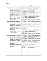
2KN/2KP
1-4-33
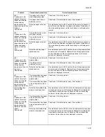
C1030
Lift motor 3 error
• When cassette 3 is inserted, lift limit
switch 3 does not turn on within 33 s of
lift motor 3 turning on. This error is
detected four times successively.
• During copying, lift limit switch 3 does
not turn on within 1 s of lift motor 3
turning on. This error is detected four
times successively.
Broken gears or
couplings of lift
motor 3.
Replace lift motor 3.
Defective lift motor
3.
Check for continuity across the coil. If none,
replace lift motor 3.
Poor contact of lift
motor 3 connector
terminals.
Reinsert the connector. Also check for conti-
nuity within the connector cable. If none,
repair or replace the cable.
Defective lift limit
switch 3.
Run maintenance item U031 and turn lift
limit switch 3 on and off manually. Replace
lift limit switch 3 if indication of the corre-
sponding sensor on the touch panel is not
displayed in reverse.
Poor contact of lift
limit switch 3 con-
nector terminals.
Reinsert the connector. Also check for conti-
nuity within the connector cable. If none,
repair or replace the cable.
Defective casette
PWB.
Replace the casette PWB
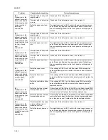
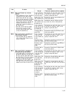
C1040
Lift motor 4 error
• When cassette 4 is inserted, lift limit
switch 4 does not turn on within 33 s of
lift motor 4 turning on. This error is
detected four times successively.
• During copying, lift limit switch 4 does
not turn on within 1 s of lift motor 4
turning on. This error is detected four
times successively.
Broken gears or
couplings of lift
motor 4.
Replace lift motor 4.
Defective lift motor
4.
Check for continuity across the coil. If none,
replace lift motor 4.
Poor contact of lift
motor 4 connector
terminals.
Reinsert the connector. Also check for conti-
nuity within the connector cable. If none,
repair or replace the cable.
Defective lift limit
switch 4.
Run maintenance item U031 and turn lift
limit switch 4 on and off manually. Replace
lift limit switch 4 if indication of the corre-
sponding sensor on the touch panel is not
displayed in reverse.
Poor contact of lift
limit switch 4 con-
nector terminals.
Reinsert the connector. Also check for conti-
nuity within the connector cable. If none,
repair or replace the cable.
Defective casette
PWB.
Replace the casette PWB.
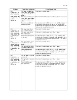
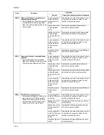
C1140
Side feeder lift motor going up error
(optional side feeder)
• Upper limit detection switch does not
turn off within 15 s of the side feeder
lift motor starting (within 200 ms during
paper feeding). This error is detected
four times successively.
Poor contact of
upper limit detec-
tion switch connec-
tor terminals.
Reinsert the connector. Also check for conti-
nuity within the connector cable. If none,
repair or replace the cable.
Defective side
feeder main PWB.
Replace the side feeder main PWB.
Defective side
feeder lift motor.
Run maintenance mode U247 and measure
the voltage between terminals YC5-A12
(side feeder main circuit board) and YC6-
B11. (Make sure all of LUSSW, UCSSW,
LLSSW and RCSSW are off.)
Despite either DC24V or DC-24V is
observed but if the side feeder lift motor
does not operate, replace the side feeder lift
motor.
Code
Contents
Remarks
Causes
Check procedures/corrective measures
Summary of Contents for TASKalfa 620
Page 1: ...SERVICE MANUAL Published in August 2009 842KP112 2KPSM062 Rev 2 TASKalfa 620 820 ...
Page 4: ...This page is intentionally left blank ...
Page 10: ...This page is intentionally left blank ...
Page 144: ...2KN 2KP 1 3 106 This page is intentionally left blank ...
Page 308: ...2KN 2KP 1 5 88 This page is intentionally left blank ...
Page 412: ...2KN 2KP 2 3 60 This page is intentionally left blank ...
Page 435: ...1 1 INSTALLATION GUIDE INSTALLATION GUIDE FOR SIDE FEEDER ...
Page 442: ...INSTALLATION GUIDE FOR LARGE SIZE SIDE FEEDER ...
Page 460: ...INSTALLATION GUIDE FOR DOCUMENT FINISHER ...
Page 475: ...INSTALLATION GUIDE FOR CENTERFOLD UNIT ...
Page 490: ...INSTALLATION GUIDE FOR MULTI JOB TRAY ...
Page 501: ...INSTALLATION GUIDE FOR PUNCH UNIT ...
Page 512: ...INSTALLATION GUIDE FOR STOPPER GUIDE ...
Page 515: ...INSTALLATION GUIDE FOR PRINTING SYSTEM ...
Page 518: ...INSTALLATION GUIDE FOR SCAN SYSTEM ...
Page 520: ......
Page 521: ......


