


2KN/2KP
1-4-59
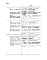
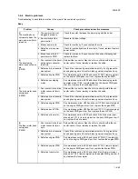
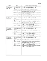
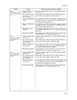
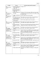
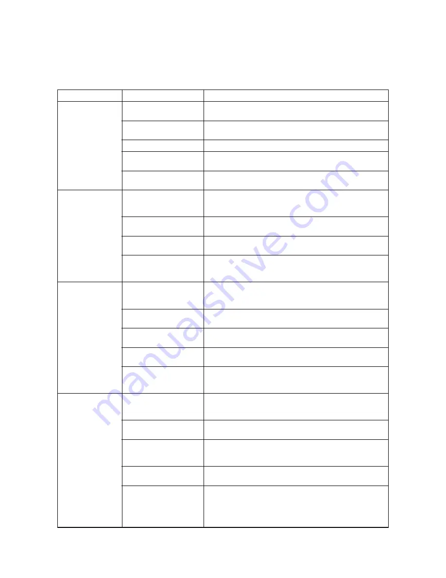
1-4-4 Electric problems
Troubleshooting to each failure must be in the order of the numbered symptoms.
Body
Problem
Causes
Check procedures/corrective measures
(1)
The machine does
not operate when the
main power switch is
turned on.
1. The power cord is not
plugged in properly.
Check the contact between the power plug and the outlet.
2. No electricity at the
power outlet.
Measure the input voltage.
3. Broken power cord.
Check for continuity. If none, replace the cord.
4. Defective main power
switch.
Check for continuity across the contacts. If none, replace the main
power switch.
5. Blown fuse in the AC
power source PWB.
Check for continuity. If none, remove the cause of blowing and
replace the fuse.
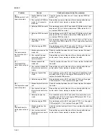
(2)
The developing
motor does not oper-
ate
(C2100).
1. Poor contact in the devel-
oping motor connector
terminals.
Reinsert the connector. Also check for continuity within the con-
nector cable. If none, remedy or replace the cable.
2. Defective drive transmis-
sion system.
Check if the rollers and gears rotate smoothly. If not, grease the
bushings and gears. Check for broken gears and replace if any.
3. Defective duplex PWB.
Run maintenance item U030 and check if YC8-3 (remote siginal)
on the duplex PWB goes low. If not, replace the duplex PWB.
4. Defective developing
motor.
Run maintenance item U030 and check if the developing motor
operates when YC8-3 (remote siginal) on the duplex PWB goes
low. If not, replace the developing motor.
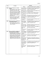
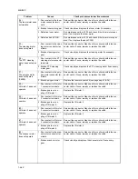
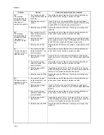
(3)
The drive motor does
not operate
(C2200).
1. Poor contact in the drive
motor connector termi-
nals.
Reinsert the connector. Also check for continuity within the con-
nector cable. If none, remedy or replace the cable.
2. Defective drive transmis-
sion system.
Check if the rollers and gears rotate smoothly. If not, grease the
bushings and gears. Check for broken gears and replace if any.
3. Defective engine PWB.
Run maintenance item U030 and check if YC3-B4 (remote siginal)
on the engine PWB goes low. If not, replace the engine PWB.
4. Defective deck PWB.
Run maintenance item U030 and check if YC11-3 (remote siginal)
on the deck PWB goes low. If not, replace the deck PWB.
5. Defective drive motor.
Run maintenance item U030 and check if the drive motor oper-
ates when YC11-3 (remote siginal) on the deck PWB goes low. If
not, replace the drive motor.
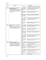
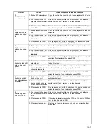
(4)
The fuser motor does
not operate
(C2300).
1. Poor contact in the fuser
motor connector termi-
nals.
Reinsert the connector. Also check for continuity within the con-
nector cable. If none, remedy or replace the cable.
2. Defective drive transmis-
sion system.
Check if the rollers and gears rotate smoothly. If not, grease the
bushings and gears. Check for broken gears and replace if any.
3. Defective engine PWB.
Run maintenance item U030 and check if YC2-B11 (remote sigi-
nal) on the engine PWB goes low. If not, replace the engine PWB.
4. Defective duplex PWB.
Run maintenance item U030 and check if YC4-3 (remote siginal)
on the duplex PWB goes low. If not, replace the duplex PWB.
5. Defective fuser motor.
Run maintenance item U030 and check if the fuser motor oper-
ates when YC4-3 (remote siginal) on the duplex PWB goes low. If
not, replace the fuser motor.
Summary of Contents for TASKalfa 620
Page 1: ...SERVICE MANUAL Published in August 2009 842KP112 2KPSM062 Rev 2 TASKalfa 620 820 ...
Page 4: ...This page is intentionally left blank ...
Page 10: ...This page is intentionally left blank ...
Page 144: ...2KN 2KP 1 3 106 This page is intentionally left blank ...
Page 308: ...2KN 2KP 1 5 88 This page is intentionally left blank ...
Page 412: ...2KN 2KP 2 3 60 This page is intentionally left blank ...
Page 435: ...1 1 INSTALLATION GUIDE INSTALLATION GUIDE FOR SIDE FEEDER ...
Page 442: ...INSTALLATION GUIDE FOR LARGE SIZE SIDE FEEDER ...
Page 460: ...INSTALLATION GUIDE FOR DOCUMENT FINISHER ...
Page 475: ...INSTALLATION GUIDE FOR CENTERFOLD UNIT ...
Page 490: ...INSTALLATION GUIDE FOR MULTI JOB TRAY ...
Page 501: ...INSTALLATION GUIDE FOR PUNCH UNIT ...
Page 512: ...INSTALLATION GUIDE FOR STOPPER GUIDE ...
Page 515: ...INSTALLATION GUIDE FOR PRINTING SYSTEM ...
Page 518: ...INSTALLATION GUIDE FOR SCAN SYSTEM ...
Page 520: ......
Page 521: ......


