


2KN/2KP
1-5-31
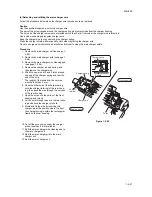
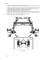
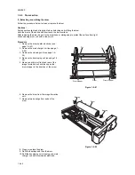
(2) Detaching and refitting the scanner wires
Take the following procedure when the scanner wires are broken or to be replaced.
(2-1)Detaching the scanner wires
Procedure
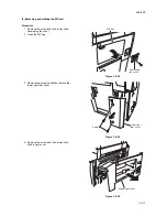
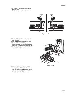
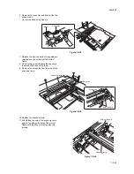
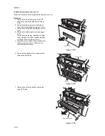
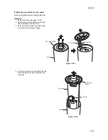
1. Remove three screws and slide the upper
left cover to machine rear.
Remove the upper left cover.
Figure 1-5-63
2. Remove the exposure lamp (see page 1-5-
28).
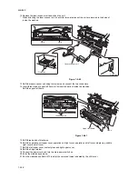
3. Remove the DP (see page 1-5-73).
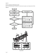
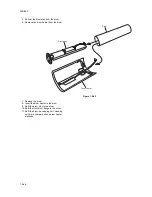
4. Remove the upper rear cover.
Figure 1-5-64
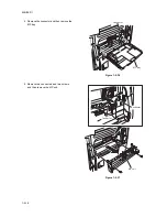
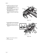
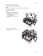
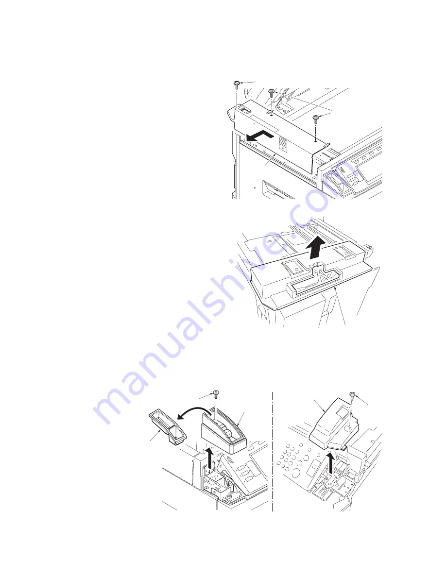
5. Remove the middle right cover (see page 1-
5-17).
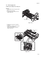
6. Remove the staple tray.
Remove each screw and then remove the
operation unit right and left covers.
Figure 1-5-65
Upper left cover
Screws
Screw
Upper rear cover
Operation unit
left cover
Staple tray
Screw
Screw
Operation unit
right cover
Summary of Contents for TASKalfa 620
Page 1: ...SERVICE MANUAL Published in August 2009 842KP112 2KPSM062 Rev 2 TASKalfa 620 820 ...
Page 4: ...This page is intentionally left blank ...
Page 10: ...This page is intentionally left blank ...
Page 144: ...2KN 2KP 1 3 106 This page is intentionally left blank ...
Page 308: ...2KN 2KP 1 5 88 This page is intentionally left blank ...
Page 412: ...2KN 2KP 2 3 60 This page is intentionally left blank ...
Page 435: ...1 1 INSTALLATION GUIDE INSTALLATION GUIDE FOR SIDE FEEDER ...
Page 442: ...INSTALLATION GUIDE FOR LARGE SIZE SIDE FEEDER ...
Page 460: ...INSTALLATION GUIDE FOR DOCUMENT FINISHER ...
Page 475: ...INSTALLATION GUIDE FOR CENTERFOLD UNIT ...
Page 490: ...INSTALLATION GUIDE FOR MULTI JOB TRAY ...
Page 501: ...INSTALLATION GUIDE FOR PUNCH UNIT ...
Page 512: ...INSTALLATION GUIDE FOR STOPPER GUIDE ...
Page 515: ...INSTALLATION GUIDE FOR PRINTING SYSTEM ...
Page 518: ...INSTALLATION GUIDE FOR SCAN SYSTEM ...
Page 520: ......
Page 521: ......


