


2KN/2KP
1-5-40
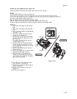
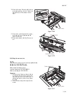
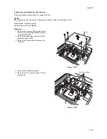
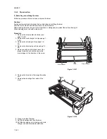
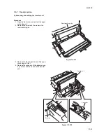
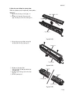
6. Check or replace the ISU.
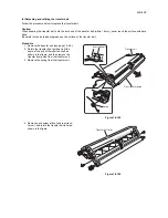
7. Position ISU at the frame hole number as
same as the number indicated on the lens of
ISU image scanning unit and insert two
positioning pins to the holes.
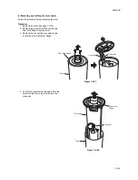
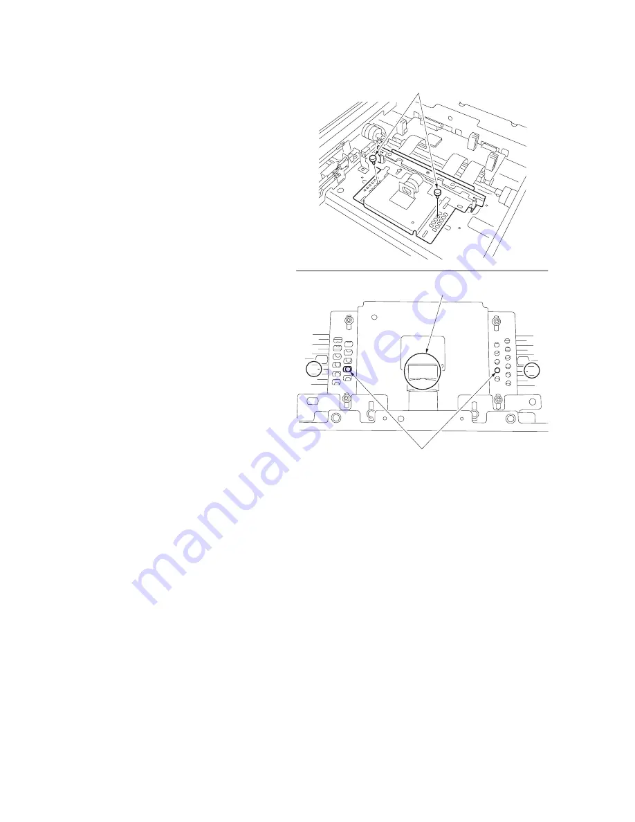
* Example: When 7 is indicated on the lens,
position ISU at the positioning hole 7 indi-
cated on the scanner unit, and inset two
positioning pins.
Figure 1-5-84
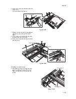
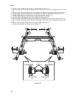
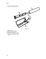
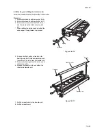
8. Refit the ISU using four screws and then
remove two positions pins.
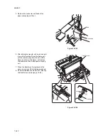
9. Refit three flexible flat cables.
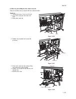
10. Refit the ISU cover.
11. Refit the contact glass and upper right
cover.
12. Refit the hinge retainer.
0
1
2
4
5
6
7
8
9
X
3
0
1
2
4
5
6
7
7
8
9
X
3
Positioning pins
Positioning holes
Lens number
Summary of Contents for TASKalfa 620
Page 1: ...SERVICE MANUAL Published in August 2009 842KP112 2KPSM062 Rev 2 TASKalfa 620 820 ...
Page 4: ...This page is intentionally left blank ...
Page 10: ...This page is intentionally left blank ...
Page 144: ...2KN 2KP 1 3 106 This page is intentionally left blank ...
Page 308: ...2KN 2KP 1 5 88 This page is intentionally left blank ...
Page 412: ...2KN 2KP 2 3 60 This page is intentionally left blank ...
Page 435: ...1 1 INSTALLATION GUIDE INSTALLATION GUIDE FOR SIDE FEEDER ...
Page 442: ...INSTALLATION GUIDE FOR LARGE SIZE SIDE FEEDER ...
Page 460: ...INSTALLATION GUIDE FOR DOCUMENT FINISHER ...
Page 475: ...INSTALLATION GUIDE FOR CENTERFOLD UNIT ...
Page 490: ...INSTALLATION GUIDE FOR MULTI JOB TRAY ...
Page 501: ...INSTALLATION GUIDE FOR PUNCH UNIT ...
Page 512: ...INSTALLATION GUIDE FOR STOPPER GUIDE ...
Page 515: ...INSTALLATION GUIDE FOR PRINTING SYSTEM ...
Page 518: ...INSTALLATION GUIDE FOR SCAN SYSTEM ...
Page 520: ......
Page 521: ......


