


2KN/2KP
1-5-57
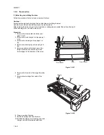
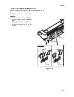
(3) Detaching and refitting the PTC wire
Follow the procedure below when the charger wire is broken or to be replaced.
Precautions
Use the specified tungsten wire for the PTC wire.
The part of the wire wrapped around the charger spring must not protrude from the PTC housing.
The cut end of the PTC wire must not protrude more than 2 mm from under the charger pin.
Use a clean, undamaged tungsten PTC wire.
Keep the PTC wire taut by stretching the charger spring.
Clean the PTC shield with wet and dry cloth when replacing the PTC wire.
Do not use organic solvents such as alcohol and thinner to clean the PTC shield.
Procedure
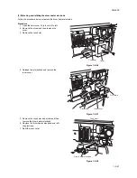
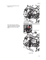
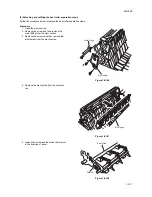
1. Remove the PTC unit (see page 1-5-56).
2. Remove the PTC cleaning pad (see page 1-
5-56).
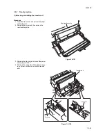
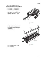
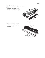
3. Remove the front and rear covers from the
PTC unit.
Figure 1-5-120
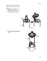
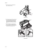
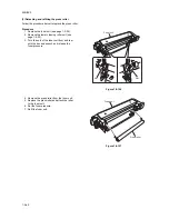
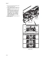
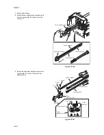
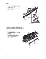
4. Remove the charger pin and spring, and
then remove the PTC wire.
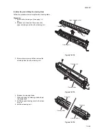
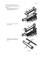
5. Wind the new tungsten wire at 4 and 6 turns
around one end of the charger spring and
trim the end of the wire.
* The length of the twists and the cut wire
must be less than 2 mm.
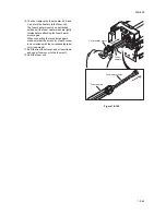
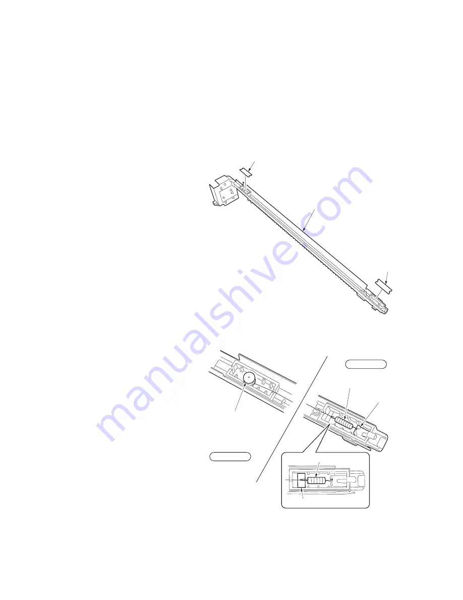
6. Hook the other end of the charger spring
onto the charger terminal of the rear hous-
ing, then pass the wire through the notch of
the rear housing.
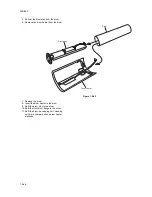
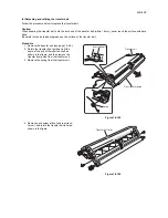
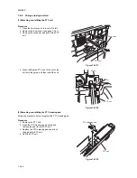
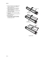
7. Let the wire through the cut in the front
housing and above the charger pin hole.
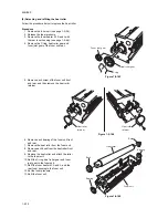
8. Strain and fix the wire by inserting the
charger pin at the position where the tip of
the charger spring is within the rectangular
frame on the rear housing.
9. Cut off the excess wire under the charger
pin so less than 2 mm protrudes.
Figure 1-5-121
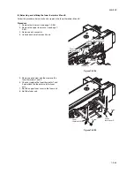
10. Refit the front and rear covers of PTC unit,
PTC cleaning pad to the PTC unit.
11. Refit the PTC unit.
Front cover
PTC unit
Rear cover
Charger pin
Charger spring
Charger terminal
Charger spring
Square
Front housing
Rear housing
Summary of Contents for TASKalfa 620
Page 1: ...SERVICE MANUAL Published in August 2009 842KP112 2KPSM062 Rev 2 TASKalfa 620 820 ...
Page 4: ...This page is intentionally left blank ...
Page 10: ...This page is intentionally left blank ...
Page 144: ...2KN 2KP 1 3 106 This page is intentionally left blank ...
Page 308: ...2KN 2KP 1 5 88 This page is intentionally left blank ...
Page 412: ...2KN 2KP 2 3 60 This page is intentionally left blank ...
Page 435: ...1 1 INSTALLATION GUIDE INSTALLATION GUIDE FOR SIDE FEEDER ...
Page 442: ...INSTALLATION GUIDE FOR LARGE SIZE SIDE FEEDER ...
Page 460: ...INSTALLATION GUIDE FOR DOCUMENT FINISHER ...
Page 475: ...INSTALLATION GUIDE FOR CENTERFOLD UNIT ...
Page 490: ...INSTALLATION GUIDE FOR MULTI JOB TRAY ...
Page 501: ...INSTALLATION GUIDE FOR PUNCH UNIT ...
Page 512: ...INSTALLATION GUIDE FOR STOPPER GUIDE ...
Page 515: ...INSTALLATION GUIDE FOR PRINTING SYSTEM ...
Page 518: ...INSTALLATION GUIDE FOR SCAN SYSTEM ...
Page 520: ......
Page 521: ......


