


3
A
G
8
9
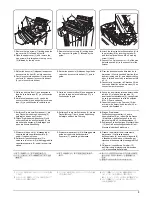
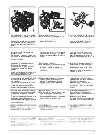
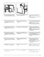
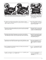
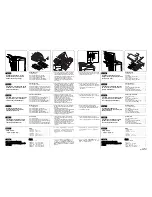
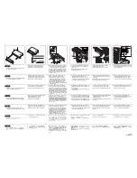
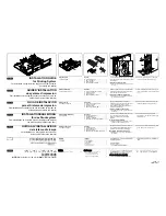
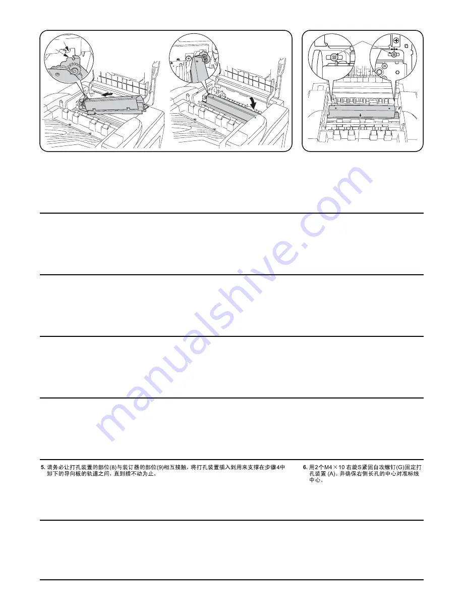
5. パンチユニットの (8) をフィニッシャの (9) に当てながら、パンチユニットを奥に差し込み、
手
順 4 で外したガイド板の入っていたレールの間に入れる。
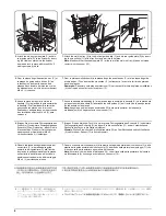
6. パンチユニット (A) をビス M4 × 10 タップ
タイト S (G)2 本で取り付ける。
右側の目盛りの中央に長穴の中心を合わせ
て取り付けること。
5.
Making sure that part (8) of the punch unit is touched part (9) of the finisher, insert the punch unit
as far as it will go between the rails that held the guide plate you removed in step 4.
6.
Secure the punch unit (A) with two M4
×
10
Tap Tight S screws (G). Make sure the cen-
ter of the right long hole is aligned with the
center of the guideline.
5.
En veillant à ce que la partie de l’unité de perforation (8) soit en contact avec la partie du
retoucheur (9), insérer l’unité de perforation aussi loin que possible entre les rails supportant la
plaque de guidage retirée à l’étape 4.
6.
Fixer l’unité de perforation (A) à l’aide de
deux vis S taraudées M4
×
10 (G). S’assurer
que le centre de l’orifice allongé droit est
aligné sur le centre du guide.
5.
Asegúrese de que la parte (8) de la perforadora está en contacto con la parte (9) del finalizador y,
a continuación, inserte la perforadora todo lo que pueda entre los carriles que sujetan la placa
guía que quitó en el paso 4.
6.
Asegure la perforadora (A) con dos tornillos
de ajuste M4
×
10 S (G). Asegúrese de que
el centro del hueco alargado derecho está
alineado con el centro de la línea de guía.
5.
Setzen Sie die Lochereinheit auf die Führungsschienen, die von der in Schritt 4 entfernten
Führungsplatte gehalten wurden, schieben Sie die Lochereinheit so weit wie möglich ein und
achten Sie dabei darauf, dass das Teil (8) der Lochereinheit das Teil (9) des Finishers berührt.
6.
Sichern Sie die Lochereinheit (A) mit den
beiden M4
×
10 Passstift-Verbundschrauben
(G). Stellen Sie sicher, dass die Mitte des
rechten Langlochs auf die Mitte der
Führungslinie ausgerichtet ist.
5.
Assicurandosi che la parte (8) dell’unità di perforazione tocchi la parte (9) della finitrice, inserire
l’unità di perforazione fino in fondo tra le guide che reggevano la piastra guida rimossa nel passo
4.
6.
Fissare l’unità di perforazione (A) con due
viti con testa a croce S M4
×
10 (G).
Assicurarsi che il centro del foro allungato
destro sia allineato al centro dalla linea
guida.
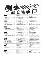
Summary of Contents for TASKalfa 620
Page 1: ...SERVICE MANUAL Published in August 2009 842KP112 2KPSM062 Rev 2 TASKalfa 620 820 ...
Page 4: ...This page is intentionally left blank ...
Page 10: ...This page is intentionally left blank ...
Page 144: ...2KN 2KP 1 3 106 This page is intentionally left blank ...
Page 308: ...2KN 2KP 1 5 88 This page is intentionally left blank ...
Page 412: ...2KN 2KP 2 3 60 This page is intentionally left blank ...
Page 435: ...1 1 INSTALLATION GUIDE INSTALLATION GUIDE FOR SIDE FEEDER ...
Page 442: ...INSTALLATION GUIDE FOR LARGE SIZE SIDE FEEDER ...
Page 460: ...INSTALLATION GUIDE FOR DOCUMENT FINISHER ...
Page 475: ...INSTALLATION GUIDE FOR CENTERFOLD UNIT ...
Page 490: ...INSTALLATION GUIDE FOR MULTI JOB TRAY ...
Page 501: ...INSTALLATION GUIDE FOR PUNCH UNIT ...
Page 512: ...INSTALLATION GUIDE FOR STOPPER GUIDE ...
Page 515: ...INSTALLATION GUIDE FOR PRINTING SYSTEM ...
Page 518: ...INSTALLATION GUIDE FOR SCAN SYSTEM ...
Page 520: ......
Page 521: ......


