background image

- 14 -

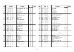
Maintenance Schedule

7-3

Maintenance schedule and specified values

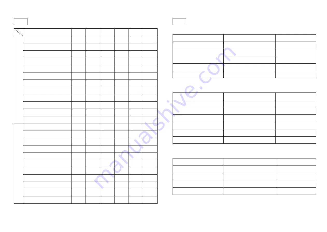
Engine oil capacity

About 3.6 liters

CD class or above

Coolant capacity

About 6 liters

Including reserve tank

Tire air pressure

Front tires: 120 kPa (1.2 kgf/cm)

Rear tires: 150 kPa (1.5 kgf/cm)

Fuel tank capacity

About 28 liters

Diesel

Hydraulic oil tank capacity

About 24 liters

Shell Tellus 46 equivalent

List of expendable products for engine/hydraulics


 Parts


 Code number


Parts catalog number

Oil element

PF16271 - 3209 - 2 

   6-121

Air cleaner element

PFT0270 - 1632 - 0 

   6-122

Fan belt

PF1G345 - 9701 - 0 

   6-123

Fuel filter element

PF15231 - 4356 - 0 

   6-120

Battery

K3600000160 

    6-18

Hydraulic filter element

K3412000060 

    9-72

Wire list


 Parts


 Code number


 Parts catalog number

Throttle wire

K1110101000 

  6-106

Break wire 1410

K1120141010 

   3-24

Break wire 1020

K1120102000 

   3-29

Break wire 1250

K1120125000 

   3-17


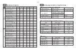
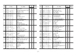
Maintenance schedule and specified values 

7-4

    Maintenance operations

Inspecting engine oil

Changing engine oil

Changing oil filters

Cleaning radiator and oil cooler

Inspecting coolant

Cleaning the air cleaner

Changing the air cleaner element

Inspecting the fan belt

Inspecting the battery fluid

Inspecting the fuel

Cleaning the fuel filter

Changing the fuel filter

Inspecting the tires

Inspecting the hydraulic oil

Changing the hydraulic oil

Changing oil filters

Inspecting the brakes

Oil leaks

Inspecting for loose or damaged parts

Lubrication (rear wheels, mower) 

Inspecting the hydraulic motor housing grease

Adjusting reel cutter blades

Removing grass and debris

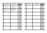
  ○

  ○

  ○

  ○

First 

50 hours

First 

50 hours

First 

100 hours

First 

100 hours

Engine

Body

Before 

operating

Every 

50 hours

Every 

100 hours

Every 

200 hours

Every 

500 hours

Every 

6 months

Summary of Contents for Baroness LM282

Page 1: ...arts catalogue SN 10011 2007 Required reading Before using the machine please ensure that you have read this manual and the operating and instruction manual for the engine Compact Light Weight 5 Reel...

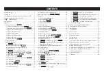
Page 2: ...cting for Leaks 12 6 5 Inspecting the Battery 13 6 6 NTN Constant Velocity Joints 13 7 Maintenance Cautions 13 7 1 Maintenance procedures 13 7 2 Preventing injuries from high pressure oil 13 7 3 Maint...

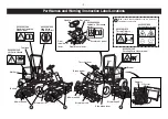
Page 3: ...d provide important information Be sure to observe the warnings and to operate the machine safely Explanations of the warning labels used in this manual and on the machine are provided to ensure safet...

Page 4: ...Objects Hazard label One of each label is affixed to the top of each of the mower reel covers K4205001530 Rotating Parts Hazard label K4209000980 Hydraulic Oil Hazard symbol Handle Muffler Fuel tank...

Page 5: ...is running could result in injury Pressurised Oil symbol Read the operation manual Cutting of Hand or Foot Risk of injury unless the rotating part is stopped and the engine shut off Thrown Objects Al...

Page 6: ...lock has been applied to mower units 4 and or 5 the mower can be set to triple mowing or to quadruple mowing on the left and right for example enabling you to adjust the mowing width to suit the condi...

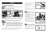
Page 7: ...t and then turning it slowly to the left Warning Level the engine and then use a dipstick to check the quantity of oil If the dipstick indicates the quantity of oil is between the upper and lower limi...

Page 8: ...ng the mower so make sure to tighten them 2 Tighten all parts M6 M8 M10 M12 M14 Standard bolt 8 80 18 180 36 360 60 600 90 900 Air pressure Front wheels 120 kPa 1 2 kgf cm2 Rear wheels 150 kPa 1 5 kgf...

Page 9: ...l raise lower lever Reel rotation lever Handle Accelerator pedal Starting up the engine 1 Sit in the seat 2 Pull the throttle lever to slightly beyond the LOW position 3 When the key is turned to the...

Page 10: ...on lever 3 8 Make sure that the reel rotation lever is placed in neutral until just before mowing or lapping The reel rotation lever should be placed in neutral when the mower is being used for anythi...

Page 11: ...ve Stop Open The stop valve prevents the mower units from falling when they are in their raised positions It is attached to the bottom right of the front of the seat Stop valve 3 12 Put the stop valve...

Page 12: ...emain the same Accelerator pedal Reel raise lower lever Reel rotation lever Never suddenly accelerate or bring the mower to a sudden stop It is dangerous and could result in damage to the hydraulics c...

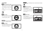
Page 13: ...s the amount of fuel No 2 diesel fuel remaining in the fuel tank Add more fuel as soon as possible when the Fuel Gauge approaches E empty Fuel Gauge 5 3 The lamp turns on when the key switch is turned...

Page 14: ...lter should be changed at the same time 3 Remove the oil drain plug located on the bottom of the hydraulic oil tank to drain the dirty hydraulic oil 4 If the hydraulic oil becomes cloudy or milky chan...

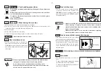
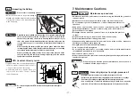
Page 15: ...after becoming familiar with the procedure to be performed Maintenance should only be performed in a level dry and clean location Do not attempt to perform maintenance or add oil while the machine is...

Page 16: ...01000 6 106 Break wire 1410 K1120141010 3 24 Break wire 1020 K1120102000 3 29 Break wire 1250 K1120125000 3 17 Maintenance schedule and specified values 7 4 Maintenance operations Inspecting engine oi...

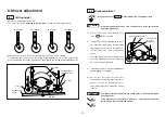
Page 17: ...e stop lever to the STOP position 2 To adjust the reel cutter and bed knife move the cutter adjustment nut so that the blade edges make uniform contact then adjust so that the blades can cut two newsp...

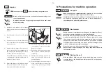
Page 18: ...emove any remaining polishing agent Lapping 8 3 Reel raise lower lever Reel rotation lever Please see section Reel rotation stop changeover lever 3 13 9 Precautions for machine operation hot parts Cau...

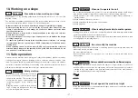
Page 19: ...obstacles and the condition of the lawn The operator should be familiar with the inspection and repair of the unit In addition the operator should be well trained in the handling of the unit and shoul...

Page 20: ...he battery and then charge it before storing in a well ventilated room For details see the battery manual Fill the tires to slightly more than the standard air pressure and park the vehicle on top of...

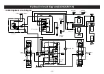
Page 21: ...old 1 mower cylinder 2 mower cylinder 3 mower cylinder 4 and 5 mower cylinder 2 3 4 5 1 Oil cooler Suction filter T Charge 3 2 5 1 4 R B2 A2 B1 T P P A1 B1 A2 B2 A3 B3 T L EF P T M2 M4 M1 A2 A1 B1 B2...

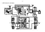
Page 22: ...e Hydraulic pump Stop valve Manifold 1 mower cylinder 2 mower cylinder 3 mower cylinder 2 3 1 Oil cooler Suction filter T Charge 3 2 5 1 4 R B2 A2 B1 T P P A1 B1 A2 B2 A3 B3 T L EF P T M2 M4 M1 A2 A1...

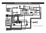
Page 23: ...ed and green AV0 85 Grenn AV1 25 Re and whi t e AV1 25 Re and whi t e AV1 25 White AV1 25 Brown AV0 85 White and black AV2 White AV2 Red AV0 85 Blue AV0 85 Orange AV0 85 Black AV0 85 Green AV0 85 Gree...

Page 24: ...22 MEMO...

Page 25: ...s catalogue are controlled by computer For prevention of delivery of wrong parts advise us of the catalogue No code No and part name Example Catalogue No Code No Part Name Qty 1 6 K1730000010 steering...

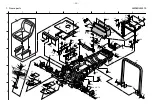
Page 26: ...7 65 65 66 68 68 66 49 61 47 15 65 67 65 65 65 47 15 47 79 55 42 66 66 66 60 65 23 25 38 24 30 30 34 35 36 28 31 29 33 32 39 54 37 15 33 32 45 44 27 59 43 63 69 70 63 69 70 20 19 18 16 17 65 64 65 1 6...

Page 27: ...4 2 1 2 2 5 1 1 1 1 1 1 1 2 1 4 1 46 1 47 1 48 1 49 1 51 1 52 1 53 1 54 1 55 1 56 1 57 1 58 1 59 1 60 1 61 1 63 1 64 1 65 1 66 1 67 1 68 1 69 1 70 1 72 1 73 1 74 1 75 1 76 1 77 1 78 1 79 1 80 heat in...

Page 28: ...29 54 55 55 56 57 58 59 60 61 13 7 6162 62 6 65 68 72 93 8 7 13 67 71 8 72 73 74 69 70 53 8 7 13 12 19 90 except 12 46 89 except 12 12 79 79 79 79 79 79 79 84 88 87 85 86 79 50 51 52 52 79 79 79 79 7...

Page 29: ...65 2 66 2 67 2 68 2 69 2 70 2 71 2 72 2 73 2 74 2 75 2 76 2 77 2 78 2 79 2 80 2 81 2 82 2 83 2 84 D R engine rotation mark engine side cover L fuel tank under urethane frame urethane bonnet urethane...

Page 30: ...29 54 55 55 56 57 58 59 60 61 13 7 6162 62 6 65 68 72 93 8 7 13 67 71 8 72 73 74 69 70 53 8 7 13 12 19 90 except 12 46 89 except 12 12 79 79 79 79 79 79 79 84 88 87 85 86 79 50 51 52 52 79 79 79 79 7...

Page 31: ...CC metal washer 832 8 nut with flange front cover L with mark front cover R with mark hot parts hazard label center cover rear rubber catch assembly 0 0 0 0 0 0 1 1 1 1 4 4 4 1 1 1 1 1 Cat No Code No...

Page 32: ...24 51 52 28 25 49 16 29 14 15 10 9 8 46 47 50 1 42 3 2 4 31 34 35 36 15 15 14 14 15 14 16 26 20 19 7 38 44 37 43 39 40 41 4 3 1 42 46 47 7 8 9 10 14 15 16 16 17 13 2 29 1 A 2 3 4 5 B C D E 3 Front wh...

Page 33: ...2 washer 2 split pin 20 limit switch D4A 4717N brake wire 1020 brake assembly with lever L pedal shaft tension return spring brake pedal tyre 24x13 00 12 4PTL wheel 10 5x12 rim valve TR413 valve core...

Page 34: ...8 9 1 38 25 22 23 24 13 33 41 14 26 27 28 28 25 20 21 22 23 24 15 41 13 29 30 31 32 22 35 16 42 43 16 42 43 17 36 37 34 20 21 19 2 39 3 4 5 6 1 38 9 10 12 11 8 7 1 A 2 3 4 5 B C D E 4 Rear wheel part...

Page 35: ...le thrust bearing 51107 O ring P48 8 spring pin 50 10 bolt 35 10 nut 1C5191P metal washer 3050 pivot pin 3 2SPHC metal washer 1635 16S washer 16 nut tie rod end R assembly tie rod 17 special nut P1 5...

Page 36: ...6 35 34 6 10 11 8 22 23 26 9 7 8 34 12 13 39 16 14 17 37 36 25 17 17 20 21 14 17 16 19 38 18 39 39 39 31 32 15 39 25 24 16 14 14 16 33 27 28 29 30 28 29 31 39 15 38 1 A 2 3 4 5 B C D E 5 Pedal parts...

Page 37: ...21105 rod 3 compression spring 2180 center fitting 4 split pin 40 1SPCC metal washer 1624 idle lever grease nipple idle lever shaft rod 10 left hand thread nut L ball LHSA10L transmission lever 10 bo...

Page 38: ...32 36 59 60 61 62 63 43 64 65 3 68 69 132 43 42 41 128 38 128 66 36 58 43 24 30 17 2 3 4 5 6 43 53 54 55 56 57 129 52 117 118 119 120 130 126 131 132 126 128 36 136 70 37 71 72 132 76 78 67 133 73 134...

Page 39: ...5 6 46 6 47 6 48 6 50 6 51 6 52 6 53 6 54 6 55 6 56 6 57 6 58 6 59 6 60 6 61 6 62 6 63 6 64 6 65 6 66 6 67 6 68 6 69 6 70 6 71 6 72 6 73 6 75 6 76 6 77 6 78 6 79 10S washer muffler pipe stay ground wi...

Page 40: ...36 59 60 61 62 63 43 64 65 3 68 69 132 43 42 41 128 38 128 66 36 58 43 24 30 17 2 3 4 5 6 43 53 54 55 56 57 129 52 117 118 119 120 130 126 131 132 126 128 36 136 70 37 71 72 132 76 78 67 133 73 134 13...

Page 41: ...1 1 1 1 6 118 6 119 6 120 6 121 6 122 6 123 6 124 6 125 6 126 6 127 6 128 6 129 6 130 6 131 6 132 6 133 6 134 6 135 6 136 6 137 6 138 6 139 6 140 6 141 6 142 6 143 6 144 6 145 fan belt plug drain bol...

Page 42: ...68 84 65 66 60 61 73 74 39 23 23 24 24 22 25 25 26 31 32 32 32 33 81 21 3 10 3 9 4 85 86 87 88 5 6 95 71 71 82 75 76 62 83 70 59 45 41 59 71 75 76 53 83 89 53 83 89 81 69 69 58 58 59 59 72 77 78 70 8...

Page 43: ...7 43 7 44 7 45 7 46 7 47 7 50 7 51 7 53 7 54 7 55 7 56 7 57 7 58 7 59 7 60 7 61 7 62 7 63 7 64 7 65 7 66 7 67 7 68 7 69 7 70 7 71 7 72 7 73 7 74 7 75 7 76 7 77 7 78 7 79 adaptor 1013 6 SSC140 hose 57...

Page 44: ...64 94 6 6 67 81 43 44 57 68 84 65 66 39 23 23 24 24 22 25 25 26 31 32 32 32 33 81 21 3 10 3 9 86 87 88 4 85 5 6 95 71 82 90 91 71 90 91 92 93 89 83 53 89 83 53 94 81 69 69 58 58 59 59 72 80 1 A 2 3 4...

Page 45: ...it orbit roll UBS070A08GCD orbit roll UBS070A08GCD seal kit orbitrollUBS070A08GCDvalvesealkit 40 90 cylinder 340 WP70 6 hose 1 680 SP 12 coil tube 580 WP70 6 hose 2 750 SP 12 coil tube 650 tapered plu...

Page 46: ...4 4 11 5 6 7 9 10 12 13 14 15 16 8 42 19 3 4 4 22 5 6 7 17 18 20 21 32 33 36 32 33 1 2 34 35 34 35 3 3 4 4 11 43 44 5 6 7 11 30 31 31 41 41 4 4 9 10 3 7 11 4 3 6 5 4 34 35 34 35 3 7 11 4 3 6 5 4 8 42...

Page 47: ...1070 manifold special tee PT1 4PF1 4 plate with shaft 50 harness clip M8 8 bolt with flange 20 1 1 9 16 10 10 10 5 2 2 5 1 1 2 2 1 1 1 1 2 2 1 2 2 2 2 2 2 4 4 1 2 1 1 4 8 42 8 43 8 44 8 45 8 46 8 47...

Page 48: ...e 14 15 56 16 8 42 19 3 4 4 22 52 53 50 51 32 33 36 32 33 54 55 46 47 46 47 48 49 46 47 46 47 48 49 3 4 4 11 43 44 48 49 57 11 30 31 31 41 45 45 4 4 3 4 4 8 42 8 42 40 40 40 37 37 61 44 43 43 44 57 59...

Page 49: ...1070 manifold special tee PT1 4PF1 4 plate with shaft 50 harness clip M8 8 bolt with flange 20 1 1 9 16 10 10 10 5 2 2 5 1 1 2 2 1 1 1 1 2 2 1 2 2 2 2 2 2 4 4 1 2 1 1 4 8 42 8 43 8 44 8 45 8 46 8 47...

Page 50: ...9 60 22 23 29 30 18 19 11 14 24 24 25 26 27 28 28 6 6 6 5 6 38 86 88 87 87 87 61 62 70 72 72 73 71 72 72 1 89 55 28 51 44 52 53 45 50 45 49 48 34 44 90 36 34 35 86 76 45 44 45 46 46 47 47 45 54 7 65 6...

Page 51: ...3 2 9 36 9 38 9 40 9 41 9 42 9 43 9 44 9 45 9 46 9 47 9 48 9 49 9 50 9 51 9 52 9 53 9 54 9 55 9 57 9 58 9 59 9 60 9 61 9 62 9 65 9 66 9 70 9 71 9 72 9 72 1 9 73 9 76 9 77 9 78 9 79 different diameter...

Page 52: ...22 23 29 30 18 19 11 14 24 24 25 26 27 28 28 6 6 6 5 6 38 86 88 87 87 87 61 62 70 72 72 73 71 72 72 1 89 55 28 51 44 52 53 45 50 45 49 48 34 44 90 36 34 35 86 76 45 44 45 46 46 47 47 45 54 7 65 66 76...

Page 53: ...T3 8 PF1 4 screwed type tee TEF PT3 8 45 elbow 1035 9 6U bolt 40 8 bolt with flange 50 8 nut with flange 10 bolt with flange 20 12 nut with flange 6 nut with flange 2 2 1 1 1 4 5 2 1 2 2 2 1 1 1 4 5 2...

Page 54: ...6 2 3 1 4 41 4 7 6 2 3 8 22 22 22 31 6 21 21 26 26 37 38 13 25 17 35 27 27 36 26 26 25 18 19 9 17 13 40 27 27 39 30 25 11 21 21 52 26 27 10 1 4 5 4 7 6 2 3 8 9 18 13 34 13 23 33 43 24 3 15 15 16 6 14...

Page 55: ...215 8 round head pin 40 20 flat head pin 57 2 3SPCC metal washer 2040 3 2 split pin 32 mower joint R front lift arm R 20 2STKM collar 25 414 5 cylinder pin 84 pin with 30 hole 196 front mower arm shaf...

Page 56: ...69 56 27 54 53 55 57 58 58 59 50 51 89 59 46 8 43 28 84 45 39 40 41 44 22 22 39 40 41 76 39 42 75 74 67 74 36 43 39 19 63 62 77 63 62 42 38 18 37 28 74 77 76 76 65 65 66 61 70 87 88 52 85 72 60 86 26...

Page 57: ...U nut P1 25 6 nut 6 washer 3 3 3 18 6 6 6 12 24 3 3 3 3 3 3 3 3 15 15 3 6 12 3 6 3 6 6 6 6 6 3 3 6 6 6 18 nut 3P1 5 18S washer 2SPCC metal washer 1828 cutting height adjusting screw 10 receiving blade...

Page 58: ...69 56 27 54 53 55 57 58 58 59 50 51 89 59 46 8 43 28 84 45 39 40 41 44 22 22 39 40 41 76 39 42 75 74 67 74 36 43 39 19 63 62 77 63 62 42 38 18 37 28 74 77 76 76 65 65 66 61 70 87 88 52 85 72 60 86 26...

Page 59: ...7 bed knife 85 770 51 mower frame rear rear mower frame thrown objects hazard label reel cover rear with mark reel cover right with mark 3 4 mower arm 6 bolt with flange 10 12 3 0 0 0 0 0 0 0 3 0 0 0...

Page 60: ...E 1 3 9 5 9 5 11 12 15 13 14 17 16 6 4 9 6 9 10 26 68 55 27 53 52 54 56 49 30 21 22 48 57 57 58 58 46 8 43 28 45 39 40 41 44 22 22 24 47 39 40 41 39 42 29 67 33 32 24 25 22 21 23 66 36 18 19 7 8 8 7 4...

Page 61: ...4 12 55 12 56 12 57 12 58 12 59 12 60 12 61 12 62 12 64 12 65 12 66 12 67 12 68 12 69 12 71 12 72 12 73 12 75 12 76 18 nut 3P1 5 18S washer 2SPCC metal washer 1828 cutting height adjusting screw 10 re...

Page 62: ...E 1 3 9 5 9 5 11 12 15 13 14 17 16 6 4 9 6 9 10 26 68 55 27 53 52 54 56 49 30 21 22 48 57 57 58 58 46 8 43 28 45 39 40 41 44 22 22 24 47 39 40 41 39 42 29 67 33 32 24 25 22 21 23 66 36 18 19 7 8 8 7 4...

Page 63: ...7 12 78 12 79 thrown objects hazard label reel cover left with mark 1 2 5 mower arm 2 0 0 1 1 1 2 mower 2 mower Cat No Code No Part Name Qty Remark LM282 LM319 Cat No Code No Part Name Qty Remark LM28...

Page 64: ...2 40 32 26 26 28 28 27 27 24 24 29 29 31 30 41 31 44 1 36 20 14 13 12 11 10 9 8 7 39 2 37 2 37 8 10 11 12 9 13 14 16 15 19 19 18 17 4 5 6 38 3 3 21 1 A 2 3 4 5 B C D E 13 Roller assembly parts LM282 L...

Page 65: ...3628 25 drum collar stopper stop ring S36 M8 grease nipple 20 nut 27 6 hollow set screw 8 roller assembly 764 grease nipple seal housing oil seal MHSA17308 1 fiber 3665 bearing 6203Z 76 2 roller 674...

Page 66: ...anual and the op erating and instruction manual for the engine Compact Light Weight 5 Reel Mower Riding Type 3 Reel Mower Instructions for use 19 26 25 24 26 25 24 10 10 4 3 7 2 1 24 27 24 27 24 20 27...

Page 67: ...bolt 15 8S washer 8 nut 2 3SPCC metal washer 832 rubber for roof 10 bolt 20 10S washer awning frame assembly awning frame awning mounting plate reinforcement rear reinforcement front roll bar L roll...

Page 68: ......

Page 69: ......

Page 70: ...1 26 Miyuki cho Toyokawa Aichi Pref 442 8530 Japan Head Office Turf Care Machinery Te l 0533 84 1221 Fax 0533 84 1220 SPEC LM282 319 2007 7...

Reviews: