5
4. Assembly Procedure
■
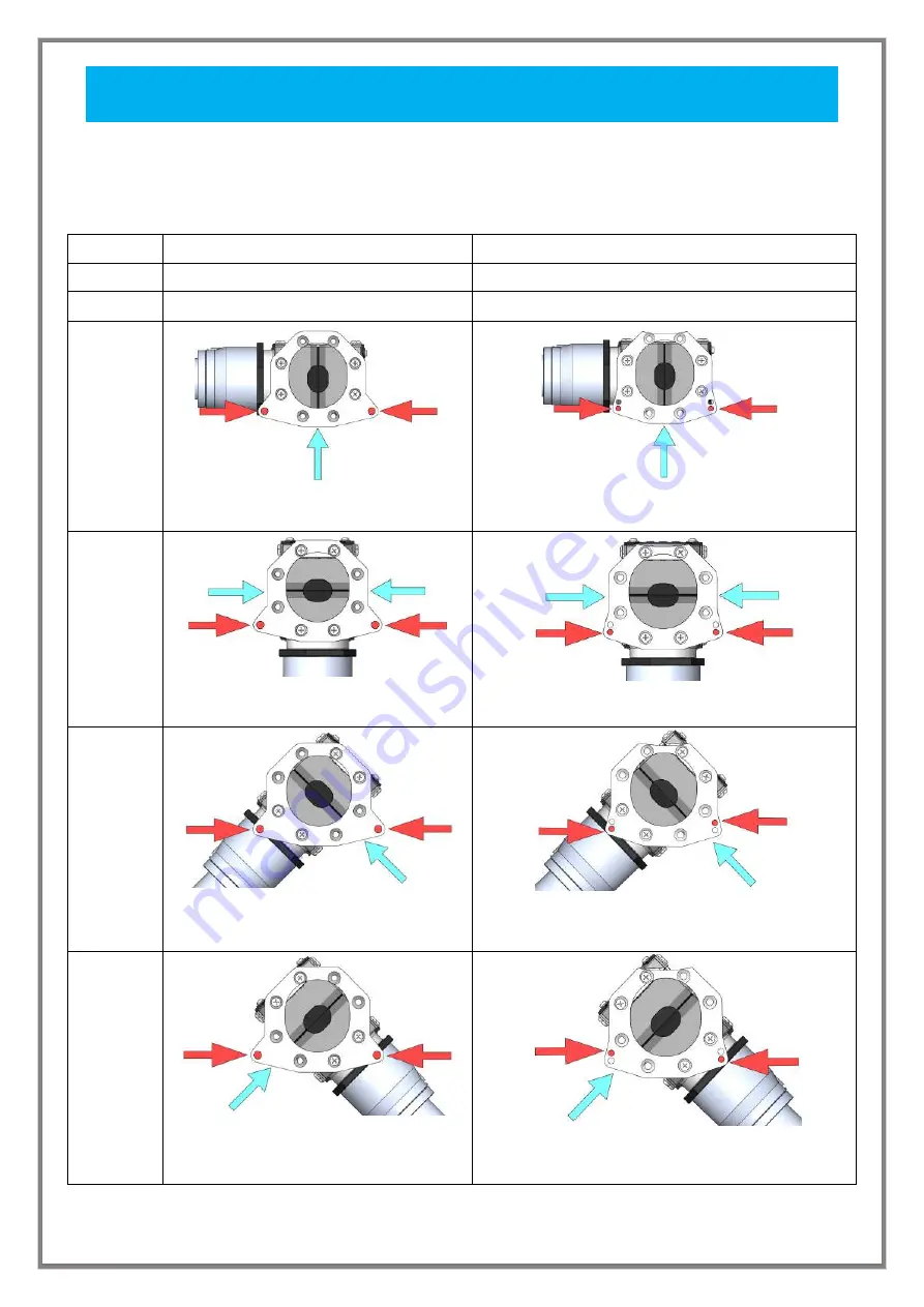
Referring to Table below, check the gun insertion procedure, and assemble the CVC4.
1. Installation model (dresser) and gun insertion direction
※
The blue arrows indicate the gun insertion direction, and the red circles indicate the positions for
connection to the dresser.
Dresser
For CD-D-F
For CDK-R
Set model
CVC4-D-1M
CVC4-K-1M
Screw
SUS cap bolt M4-L28-M4 nut
SUS cap bolt M4-L30 + SW + flat washer
Insertion
direction
Front
The vacuum unit can also be attached to
the right side
The vacuum unit can also be attached to the right
side
Right
and
Left
The gun can be inserted from both right
and left
The gun can be inserted from both right and left
Diagonally
right
forward
Note) In the case of CD-D-F, attachment
may sometimes not be possible owing to
interference with the body
The attachment screw holes are different on the right
and left
Diagonally
left
forward
Note) In the case of CD-D-F, attachment
may sometimes not be possible owing to
interference with the body
The attachment screw holes are different on the right
and left
Summary of Contents for CVC4
Page 14: ...12 MEMO...


