Digital Overcurrent & Ground Overvoltage & Selective Ground Relay (GDR-AEF01) User's Manual
39 / 67
Kyongbo Electronics Co., Ltd.
To set the desired T/S, press
,
Key to move
( * ) symbol to the desired
category.
Ÿ
System Config.
▶
T/S Output
▶
T/S 1 Setting
It is a category that can set the connection type, recovery method, and recovery
delay time, etc. for 7 output connections in T/S Output.
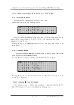
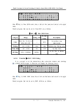
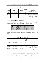
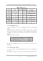
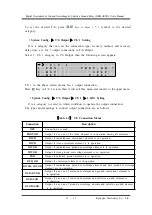
Select 1. T/S 1 category in T/S Output, then the following screen appears.
- 〉
T /
S
1
1
.
C O N
:
P R O T _ O R
*
2
.
R S T
:
S E L F
3
.
D L Y
:
0
.
0 0
s
T/S 1 in the above screen means No. 1 output connection.
Press
Key in T/S 1 screen, then it will exit this menu and convert to the upper menu.
Ÿ
System Config.
▶
T/S Output
▶
T/S 1
▶
1.CON Setting
It is a category to select in which condition to operate the output connection.
The types and meanings to connect output connection are as follows.
Connection
Description
OFF
Connection not used.
PROT_OR
Output if any one of the relay element is in operation among all elements.
IOCR
Output if instantaneous overcurrent element is in operation.
TOCR
Output if time overcurrent element is in operation.
IOVGR
Output if instantaneous ground overvoltage element is in operation.
TOVGR
Output if time ground overvoltage element is in operation.
SGR
Output if selective ground element is in operation.
OCR_OR
Output if overcurrent element is in operation
IOVGR+TOVGR
Output if instantaneous ground overvoltage element and time ground overvoltage
element are in operation.
OCR+OVGR
Output if any one of overcurrent element and ground overcurrent element is
in operation.
OCR+SGR
Output if any one of overcurrent element and selective ground element is
in operation.
OVGR+SGR
Output if any one of ground overvoltage element and selective ground element
is in operation.
【
Table 6.7
】
T/S Connection Menus


