20
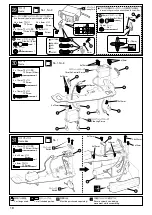
Part bags used.
No.9
No9
1
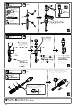
Tapered Washer
121
36
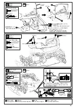
Radio
37
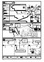
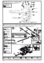
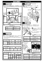
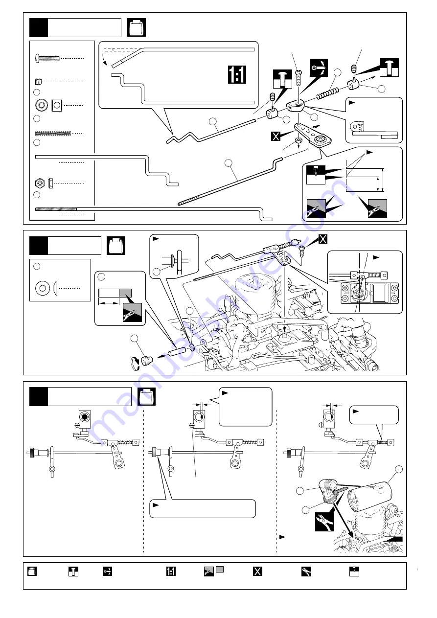
Throttle Linkage Adjustment
122
123
124
145
121
Confirm the setting
before installation.
Position where brake starts working.
Throttle Stop Screw
Adjust with throttle
stop screw.
Contracted.
( )
( Brake )
( )
( High )
( )
( Idle )
91
Silicone Tube
approx.
10mm
approx.1mm
approx.1mm
Supplied with the servo.
No.9
2
3 x 3mm
Set Screw
2
118 2mm
Stopper
1
119
Spring
Throttle Rod
Brake Rod
1
117
35
Radio
Servo Horn
Note the top
and bottom.
2x10mm
3x3mm
3x3mm
116
117
118
118
119
120
2mm
2mm
Holes used.
1
2mm
Nylon Nut
Neutral
Cut off excess.
Tentatively
tighten.
Ensure smooth non-binding
movement while assembling.
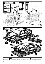
Cut off shaded
portion.
Drill holes with the
specified diameter.
2mm
True-to-scale
diagram.
Must be purchased
separately!
Note the direction.
121
1
2 x 10mm
Screw
approx.
16mm
approx.10mm
使用する袋詰。
シリコンチューブ
サーボ付属。
テーパーワッシャー
プロポ
確認後、
とりつける。
中立
スロットルリンケージ調整
ブレーキが効きはじめる位置。
スロットルストップスクリュー
スロットルスト
ップスクリュー
で調整する。
ちぢんでいる。
ブレーキ
ハイ
スロー
セットビス
ストッパー
スプリング
スロットルロッド
ブレーキロッド
1
116
プロポ
サーボホーン
上下の向きに注意。
使用する穴。
ナイロンナット
余分をカットする。
仮止め。
可動するように組立てる。
をカットする。
2mm
の穴をあける(例)。
原寸図。
別購入品。
向きに注意。
約
10mm
約
16mm
約
10mm
ビス
約
1mm
約
1mm

