background image

11

58

65

65

132

64

16

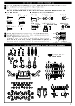
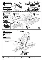
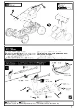
No.2, No.3, No.4

3x10mm

3x18mm

3mm

13

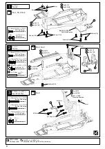
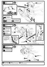
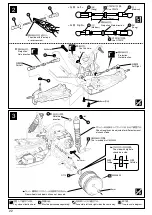
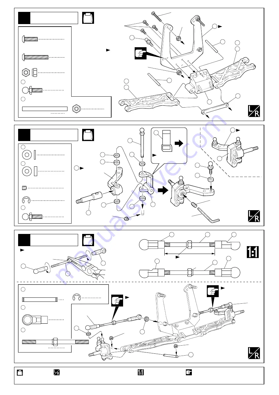
Front Suspension

2

3mm 
          Nut

58 4.8mm

            Ball Stud (L)

2

65 3 x 34mm 

                 Shaft

Use this hole.

No.3, No.4

E2.5

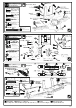
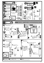
14

Front Suspension

58 4.8mm

            Ball Stud (L)

6

3 x 7 x 1mm
                  Plastic Collar

30

6

3 x 7 x 2mm
                  Plastic Collar

31

2

3 x 3mm 
     Set Screw (Apply cement to set screw)

2

E2.5

E-ring

No.3, No.4

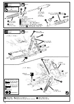
15

Front Suspension

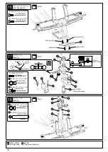
4

E2.5
          E-ring

68

Suspension Shaft (Silver)

4

21 4.8mm

            Ball End (Medium)

<            Left >

<            Right >

5

7

58

31

  6  

30

30
31

67

30

31

8

56

Hex Wrench (1.5mm)

3x3mm

(Apply cement to 
  set screw)

Note the direction.

Note the direction.

Front

8

ÒLÓ marked

ÒRÓ marked

21

134

21

68

162

162

<            Right >

<            Left >

  (Medium)

  (Medium)

38mm

21

134

134

21

  (Medium)

  (Medium)

21

21

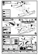
Projection. 
Note direction.

For Left

For Right

E2.5

The side with the step is 
a reverse screw.

2

Projection. 
Note direction.

Projection. 
Note direction.

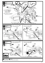
Part bags used.

Assemble left and right sides the same way.

True-to-scale diagram.

Pay close attention here!

E2.5

2

2

3mm 
                  Nylon Nut

3mm 
          Nylon Nut

2

134 3 x 50mm

                  Adjust Rod

3 x 18mm 
                 Button Cap Screw

2

3 x 10mm 
                 Button Cap Screw

3

2

193

No.30073B

133

No.30073

193

No.30073B

133

No.30073

ナット

ボールスタッド(

L

シャフト

フロントサスペンション

取付穴。

使用する袋詰。

左右同じように組立てる。

原寸図。

注意して組立てる所。

E

リング

サスシャフト(銀)

ボールエンド(中)

フロントサスペンション

左側用

右側用

段のある方が逆ネジ。

右側

左側

(中)

(中)

(中)

(中)

段のある方。

段のある方。

段のある方。

左側

右側

六角レンチ(

1.5mm

向きに注意。

向きに注意。

L

のマーク

R

のマーク

フロントサスペンション

ボールスタッド(

L

プラカラー

プラカラー

セットビス(緩み止め付き)

(緩み止め付き)

E

リング

ナイロンナット

ナイロンナット

アジャストロッド

ボタンキャップビス

ボタンキャップビス

Summary of Contents for EP ULTIMA RB Type-R EVOLUTION

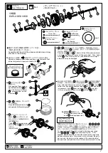
Page 1: ... model is not a toy この無線操縦模型は玩具ではありません この商品は高い性能を発揮するように設計されています 組立てに不慣れな方は 模型を良く知っている人にアド バイスを受け確実に組立ててください 小さい部品があるので 組立て作業は 幼児の手がとど かない所で必ず行ってください 動かして楽しむ場所は万一の事故を考えて 安全を確認 してから責任をもってお楽しみください 組立てた後も 説明書がいつでも見られるように大切に 保管してください First time builders should seek the advice of experienced modellers before beginning assembly and if they do not fully understand any part of the construction Assemble th...

Page 2: ...A size Batteries For Transmitter AA AA AA AA アンプ Electric speed controller 31 40mm 36 43mm 20 29mm 1 2チャンネルアンプ仕様無線操縦機 プロポ と電池 2ch with electronic speed controller and 1 servo radio control set このキットには2チャンネルアンプ仕様 のプロポが必要です 送信機にはスティックタイプとハンドル タイプがありますが お好みのタイプを 用意してください プロポの取扱いは プロポに付属の説明 書を参考にしてください スティックタイプ 2チャンネルプロポ Stick type 2ch radio set ハンドルタイプ 2チャンネルプロポ Wheel type 2ch radio set This kit requ...

Page 3: ...na Transmitter Connect the Ni Cd battery Extend the antenna Receiver Center the trims Switch on Transmitter Switch on Receiver Make sure the servos are in command Switch off Receiver Switch off Transmitter Retract the antenna Transmitter 1 2 3 4 5 6 7 8 9 10 11 始める時 終わる時 START FINISH ラジオペンチ Needle Nose Pliers ダンパー用シリコンオイル Silicone Oil for Shock ニッパー Wire Cutters モリブデン系グリス Molybdenum Grease キリ Awl ...

Page 4: ...e key no of the part needed in the spare part list and refer to the left column to look up the corresponding order no 説明書に使われているマーク Symbols used throughout the instruction manual comprise 4 エポキシ接着剤で接着する Apply epoxy glue 瞬間接着剤で接着する Apply instant glue CA glue super glue グリスを塗る Apply grease ネジロック剤を塗る Apply threadlocker screw cement 2セット組立てる 例 Assemble as many times as specified here twice x2 左右同じように組...

Page 5: ...ものもありますので 予備としてお使いください This kit contains screws and hardware in different metric sizes and shapes Before using them check the screws on the true to scale diagrams on the left side in each assembly step Some screws are extras 5 ビスの種類 SCREWS ビス Screw キャップビス Cap Screw 3x12mm サラビス F H Screw TPビス Self tapping TP Screw TPサラビス TP F H Screw セットビス Set Screw 小物部品のサイズ例 OTHER HARDWARE 3x12mm ビス Screw 3mm 12mm...

Page 6: ... 109 2 6 x 16mm Shaft 2 Chassis 3 Rear Shock Stay 3x10mm F H 3x20mm 3x15mm 3mm 111 2 3mm Nut 1 Chassis 3mm 3mm 105 3x8mm F H 3x8mm F H 3x8mm F H 3x8mm F H Note the direction Note the direction 4 3mm Nylon Nut 2 3 x 8mm F H Cap Screw 8 3 x 8mm F H Cap Screw 1 2 3 x 12mm Button Cap Screw 2 3 x 20mm Button Cap Screw 2 3 x 15mm Button Cap Screw 2 3 x 10mm F H Cap Screw 使用する袋詰 シャシー シャシー ナイロンナット 向きに注意 向...

Page 7: ...34 39 35 Now hold the differential case firmly and rotate part If part rotates into the opposite direction to part no further adjustment is necessary If part does not rotate screw is too tight In this case gradually loosen screw until part rotates As soon as the ball differential s smooth action becomes rough parts and may have become gritty If this happens disassemble the unit and clean these par...

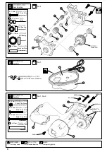
Page 8: ...1 49 5 x 16mm Aluminium Shaft 1 70 5 x 7 x 3mm Collar 3x15mm 51 106 70 51 115 52 52 51 51 49 112 113 Differential 3x5mm 3x5mm 3x25mm 3x35mm 3x35mm 118 32 119 114 Temporarily tighten 119 120 2 3 x 15mm Button Cap Screw 2 3 x 5mm Button Cap Screw 1 3 x 25mm Button Cap Screw 3 x 35mm Button Cap Screw 2 使用する袋詰 を にはめ込み余分な所をカットします 本締めする リヤギヤボックス ベアリング ベアリング アルミシャフト ギヤボックス ギヤボックス アルミシャフト をカットする カラー デフギヤ ...

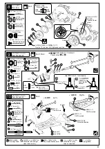
Page 9: ...mm screw x2 Assemble as many times as specified x2 E2 5 ÒL3Ó marked ÒR3Ó marked Inside Outside Note the direction 1 5 x 8mm Roll Pin 3mm 2 6mm L 3 R 3 1 160 4 x 8mm Metal Bushing 1 1 4mm Flanged Nylon 2 2 6 x 5mm Button Cap Screw 171 2 1 6 x 9mm Pin 4 5 x 7 x 0 1mm Shim 172 Choose either or A B 66 3 x 47mm Shaft 69 3 x 26mm Shaft 2 3 x 5mm Set Screw 4 174 2 x 7 8mm Pin Apply grease Spring Pin Need...

Page 10: ...ft For Right 12 Rear Gearbox 3x8mm F H Put universal shaft 3x8mm F H 3x8mm F H 3x8mm 3x8mm F H Part bags used Assemble left and right sides the same way True to scale diagram Pay close attention here 2 131 3 x 40mm Adjust Rod 3 x 8mm F H Cap Screw 4 3 x 8mm F H Cap Screw 6 3 x 8mm Button Cap Screw 2 162 162 162 リヤギヤボックス リヤサスペンション ボールエンド 中 ボールエンド 長 右側 左側 中 長 中 長 段のある方 段のある方 段のある方 段のある方が逆ネジ 左側用 右側用 ...

Page 11: ...62 162 Right Left Medium Medium 38mm 21 134 134 21 Medium Medium 21 21 Projection Note direction For Left For Right E2 5 The side with the step is a reverse screw 2 Projection Note direction Projection Note direction Part bags used Assemble left and right sides the same way True to scale diagram Pay close attention here E2 5 2 2 3mm Nylon Nut 3mm Nylon Nut 2 134 3 x 50mm Adjust Rod 3 x 18mm Button...

Page 12: ...w 2 20 4 8mm Ball End Short 5 59 4 8mm Ball Stud S 18 Steering 2mm approx 24mm 59 61 60 59 25 59 59 162 23 62 24 Short 20 3x10mm 159 159 63 29 159 159 63 3 x 8mm F H Cap Screw 2 2 3 x 10mm F H Cap Screw 4 159 5 x8 x 2 5mm Ball Bearing 2 63 5 x 31mm Aluminium Shaft 使用する袋詰 フロントサスペンション 原寸図 ステアリング ステアリング セットビス ボールエンド 短 ボールスタッド S 向きに注意 短 約24mm サラキャップビス サラキャップビス ベアリング アルミシャフト ...

Page 13: ... 26 27 3x8mm 3mm Longer than 28mm Shorter than 10mm Part bags used Assemble left and right sides the same way x2 Assemble as many times as specified Pay close attention here Must be purchased separately 1 1 2 6 x 8mm TP Screw 2 6 x 8mm Screw 3 x 8mm Button Cap Screw 2 131 3 x 40mm Adjust Rod 3 x 8mm F H Cap Screw 2 2 3 x 10mm F H Cap Screw 3 x 12mm F H Cap Screw 2 1 3 x 8mm Button Cap Screw 4 4 3m...

Page 14: ...ne sheet of paper inserted between both gears Motor 1 3 x 3mm Set Screw Must be purchased separately No 1 3x5mm 24 Gearbox 3x5mm 121 120 Hex Wrench 1 5mm 136 3x3mm 136 True to scale diagram 3 x 8mm F H Cap Screw 2 2 3 x 5mm Button Cap Screw 2 3 x 5mm Button Cap Screw 2 3mm Washer Short Short 使用する袋詰 別購入品 モーター セットビス 紙1枚分のすき間を つくって固定する モーター 平らな面にセット ビスを固定する 標準のピニオンギヤは11T程度のモーターに対応します プロポ セットビス ボールエンド...

Page 15: ...id of air bubbles Pressure Type 95 81 94 80 94 80 92 76 75 85 96 Put a little oil Complete the shock assembly in the order and Put a little oil You can assemble the shock in 2 ways 0 1mm Add oil one more time up to the brim 2 3 4 5 1 Surplus oil comes out for Front Short for Front Short for Front Short for Rear Long for Rear Long for Rear Long x2 Assemble as many times as specified 137 89 79 86 79...

Page 16: ...tic Nut 3 x 10mm Button Cap Screw 27 Shock 8 97 5 8mm Ball Front 82 98 97 84 97 83 87 For Front Short for Front Short for Rear Long for Front Short for Rear Long 150 151 Assemble left and right sides the same way 84 Note the direction 3 x 12mm Button Cap Screw 83 Use this hole Pay close attention here 2 2 使用する袋詰 フロント用 短 リヤ用 長 フロント用 短 リヤ用 長 ダンパー ボール スプリング調整用 スプリングを縮めて を入れる は5種類あるので 車高の前後が 水平になるように ...

Page 17: ...Double sided Tape 48 48 Sponge 117 Sponge 117 117 Sponge Speed Controller Antenna Connect the cords properly with reference to manuals of battery and motor 163 For straight packed Battery For straight packed Battery For Separated Battery For Separated Battery 使用する袋詰 別購入品 プロポの説明書を参考に コネクターを接続する コードをストラップで束ねる シャシーのスリットに通す アンテナ 受信機 バッテリー バッテリー プロポ バッテリー バッテリー スナップピン 両面テープ 両面テープ スポンジ スポンジ スポンジ アンプ アンテ...

Page 18: ...4mm Assemble left and right sides the same way x2 Assemble as many times as specified 53 53 144 145 142 140 143 141 Illustration from reverse side Illustration from reverse side 4mm Flanged Nylon Nut 4 53 3 16 x 3 8 Ball Bearing 4 Drive pin must fit into wheel groove 使用する袋詰 タイヤ タイヤ ピッタリはめてからタイヤとホイールの つなぎ目に瞬間接着剤を流し接着する ピッタリはめてからタイヤとホイールの つなぎ目に瞬間接着剤を流し接着する 瞬間接着剤で接着する フロント用 フロント用 リヤ用 リヤ用 リヤ リヤ フロント フ...

Page 19: ...remove the protective film from the body shell Before painting use a neutral detergent to remove any oil residues and dirt Mask the windows from the inside 1 4 2 Refer to the pictures on the box for the color scheme 3 Mask Mask 146 147 ボディ 塗装 をカットする 6mmの穴をあける 例 マスキング マスキング 京商スプレーカラーでボディ内側を塗装する 塗装後 ボディ表面の保護ビニール シートをはがしておく 塗分けはパッケージ 写真も参考にして ください 塗装前に 洗剤で油やよごれを洗う ウインドウ部分に 内側からマスキング シートを貼る ...

Page 20: ...herever you like Let item number go through the hole of the wing as shown 3x3mm Assemble in the specified order 2 3 x 3mm Set Screw 148 149 1 1 2 3 3 2 149 Part bags used No 2 ボディ デカール デカールは 好きな位置に貼って下さい を図のように通して3x3mm セットビスで固定する 番号の順に組立てる セットビス 149 使用する袋詰 ...

Page 21: ...s for looseness 38 1 Body Shell 2 48 Hook Pin 48 48 W5063 UMW409 3x5mm E2 5 Note the direction Use this hole Left Right 13 69 66 12 E2 5 ÒL3Ó marked ÒR3Ó marked L 3 R 3 Pay close attention here Must be purchased separately Assemble left and right sides the same way 走行上の注意 オプションパーツ ロングリヤサスペンションアーム UMW409 の取り付け 走行時は 必ずボディを装着してください 必要以上に前 後進の操作を繰り返すことは おやめください 下記の場所での走行は 故障の原因になりますのでおやめください シャシーにからむよ...

Page 22: ...adjusted for different amount of shock stroke This is included in UMW409 Rear wheels included in kit can not be used The side with big hole shoud be inside 3x8mm F H 3x10mm 4mm Use OTW13 Use OTW13 W5028W OT19 Inside Outside 2 3 22 131 21 87 162 162 83 The side with the step is a reverse screw Use this hole Note the direction 注意して組立てる所 左右同じように組立てる 原寸図 別購入品 右側 左側 中 長 中 長 段のある方 段のある方 段のある方 ダンパーの全長はリバ...

Page 23: ...electric motor and Ni Cd battery are hot You may burn yourself seriously touching them WARNING Do NOT operate the model in the following places and situations Non observance may lead to accidents 次のような時 場所では走らせない 思わぬ事故の原因になります 警告 WARNING in order to avoid accidents and personal injury be sure to observe the following 事故やケガ等の危険防止のため 次のことを必ずお守りください 警告 Keep in mind that people around you may also ope...

Page 24: ...he servo cords and the antenna be damaged get them repaired by their manufacturers Make sure the suspension train ist broken due to crashes Make sure that gears are not worn or damaged Remove dirt from the chassis Are all screws securely tight Are the radio batteries fully charged Are the onboard batteries fully charged Is the backlash properly adjusted Does the car s steering react according to y...

Page 25: ...ontrol is in neutral 送信機の電池をチェック Check the transmitter batteries 走行用のバッテリーを充電 Fully charge the Ni Cd battery 受信機のスイッチを切る Switch off the receiver 送信機のスイッチを切る Switch off the transmitter 走行用バッテリーのコネクター をはずす Disconnect the Ni Cd battery 3 1 2 5 4 10 6 7 8 9 1 2 3 4 5 CH 2 CH 1 BATT CH 2 CH 1 BATT CH 2 CH 1 BATT OFF ON ON ON OFF CH 2 CH 1 BATT OFF ON OFF 手もとに車を回収する After finishing running collect your ...

Page 26: ...truction manual Recharge Ni Cd battery Even when releasing throttle car does not run Electronic speed controller is not properly adjusted Adjust throttle trim transmitter Should electronic speed controller not shift into high readjust it as per in struction manual Motor runs but car does not run Pinion gear is not installed Or screw is loose Tighten screw that holds pinion gear Motor trouble Repla...

Page 27: ... Hub Carrier Ð5û スペシャルスリッパーパッド Special Slipper Pad M4スラストブッシュ M4 Thrust Bushing M4テンションスプリング M4 Tension Spring ハードキングピン Hard King Pin アクスルワッシャーセット Axle Washer Set タングステンカーバイト3 32ボール Tungsten Carbide 3 32 Ball カーボンコンポジットリヤバルクヘッド Carbon Composite Rear Bulkhead カーボンコンポジットバッテリープレート Carbon Composite Battery Plate ライトウエイトスリッパーディスク EP用 Lightweight Slipper Disc for EP SPモータープレート SP Motor Plate カーボンコンポジットメ...

Page 28: ...p Pro Shock L W6004 W5183 04が合わせて必要です use with W6004 and W5183 04 3500 ツインキャッププロショック S Twin Cap Pro Shock S テフロンダンパーケース S Teflon Shock Case S スプリング S 70 Shock Spring S 70 アンテナ Antenna スナップピン Snap Pin セイバーチューブ スプリング Servo Saver Tube Spring サーボセイバー Servo Saver スポンジテープ 1mm厚 Sponge Tape 1mm thickness 96 x 10 82 83 85 86 87 84 x 2 98 x 10 75 x 1 76 x 1 92 x 4 139 x 1 93 x 4 150 x 2 900 300 1100 1200 テフ...

Page 29: ...0 96613 シリコンオイル 700 Silicone Oil 700 96610 シリコンオイル 800 Silicone Oil 800 96614 シリコンオイル 900 Silicone Oil 900 96531 シリコンオイル 1000 Silicone Oil 1000 96615 シリコンオイル 1100 Silicone Oil 1100 96616 シリコンオイル 1200 Silicone Oil 1200 800 96506 ボールデフグリス Ball Differential Grease ボールデフ用 for Ball Differential ダンパー用 for Shocks 70902 15W 70902 16W 70902 17W 70902 18W 70902 23W 70901 10T W5183 80 W5183 75 W5183 65 W5183...

Page 30: ...48 96441 125 UMW303 UM304 108 188 126 127 186 UM129 59 UM112 20 UM145 162 UM112 20 92922 183 182 181 UM105P UMW406 UM402 12 UMW104 69 130 191 UM105P 174 UMW102 66 UM112 UMW406 UM402 21 129 131 SP107V 9 UMW404 172 UMW404 73 172 UMW404 74 171 SP107V 10 UM128 58 UM145 162 UM145 162 UM145 162 UM112 OTW12 UMW404 22 SP107V 10 145 144 BRG001 51 BRG001 51 143 W5181 04 92 W5181 02 76 151 W6004 89 UM114 32 ...

Page 31: ...一部取り扱っていないお店もございます パーツ直送便取り扱い店は このステッカーが目印 3 4日でお客様の ご自宅かお店に お届けします お店でパーツ直送便 注文用紙に 品番 と必要数を記入 パーツ直送便の 注文用紙といっしょに 代金をお店の人に 支払う 発送手数料は 不要 お届けまで 3 4日 発送手数料 200円 発送手数料 200円 お届けまで 10 12日 お届けまで 6 7日 お届けまで 3 4日 お店に行けない場合は 京商ホームページ http www kyosho co jp 内のパーツオンラインショップからお申し込みいただくか 郵便局からお申し込みいただくようになります 1 まずはお店でお求めください 現金書留の宛先 243 0034 神奈川県厚木市船子153 京商株式会社 ユーザー相談室 電話 046 229 4115 必要事項を記入した用紙と代金を現金書留 にて京商までご...

Page 32: ...わせは 月曜 金曜 祝祭日を除く 10 00 18 00 フ ァ ッ ク ス では 24時間お問い合わせの受付をして居ります 回答は 翌営業日 以降となる場合があります 営業日 月曜 金曜 祝祭日を除く これらのサービスは日本国内に限らせて頂きます ご購入店 ご使用 プロポ フリガナ 店名 メーカー名 商品名 ご氏名 ご自宅 住所 平日の昼間に 可能な連絡先 ご自宅の 連絡先 ご購入 年月日 ご使用の モーター 受付No 京商記入欄 都 道 府 県 電 話 都 道 府 県 性別 生年月日 大正 昭和 平成 男 女 電話 電話 R C歴 品番 商品名 ファックス ファックス 京商にお問い合わせの際は 京商ユーザー相談室 にご連絡ください お問い合わせの際は お手元に商品や組立 取扱説明書をご用意のうえ 組立 取扱説明書のページ数 行程番号 部品番 号 キーNo を用いるなど なるべく具体的に...

Page 33: ...E FINEST RADIO CONTROL MODELS 京商株式会社 243 0034 神奈川県厚木市船子153 ユ ザ 相談室直通 電話 046 229 4115 お問い合わせは 月曜 金曜 祝祭日を除く 10 00 18 00 PRINTED IN JAPAN 61920301 1 メーカー指定の純正部品を使用して 安全にR Cを楽しみましょう 京商ホームページ http www kyosho co jp ...

Reviews: