background image

dNaNo CCS

28

7

走行させましょう

電源の入れ方

Let's Drive!

Turn the Power Switch ON. 

Instructions from this point onwards relate to use with the PERFEX KT-18 transmitter. 

ここから先は、使用する送信機がPERFEX KT-18の場合の説明となっております。

To use this transmitter with a previously purchased chassis (dNaNo), it must undergo a pairing adjustment. 

初めてお買い上げ頂いた車体(dNaNo)を使用する場合には、

ペアリング

という設定が必要です。

08.02

Antenna

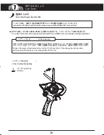
アンテナを立てる。

お買い上げ頂いた車体に使用する送信機のIDを記憶させる作業のことです。使用する送信機を変更する場合
にもペアリングを行ってください。車体と送信機をその組み合せで使用する、最初の1回目だけに行います。

Pairing is the process of registering the transmitter's ID with your chassis. If you change transmitters, please 
perform pairing. Pairing process is not required after the first time.

What is pairing ? 

ペアリングとは・・・

 /

<                                           >

How to complete pairing

<                         >

ペアリングの方法

1

Summary of Contents for FX-101 Series

Page 1: ...セットの他に必要な物 Required Additional 4 各部の名称 Glossary of Main Parts 5 バッテリーの充電 Charging Battery 6 走行の準備 Before Operating 7 走行させましょう Let s Drive 8 上手な走行テクニック Operating Tips 9 各部の交換 Replacement for Each Part 分解図 スペアパーツ Exploded View Spare Parts 故障かな Trouble Shooting 京商スペアパーツ オプションパーツの購入方法 組立や 操作上で不明な点のお問い合わせ方法 Index 目次 3 8 9 12 15 10 11 16 19 20 26 27 44 45 46 64 47 59 60 63 66 67 コンプリートシャシーセット FX 101 Ser...

Page 2: ...FX Series The dNaNo FX Series is a high performance mini R C car using the latest 2 4GHz ASF digital proportional system and is compatible with IC tag lap count systems The high performance and response 2 4GHz proportional system includes a special IC tag that is compatible with ID management systems as well as the latest lap count systems Please refer to About the IC Tag covered later To get the ...

Page 3: ...oy It is designed for users over 14 years of age 不要になったバッテリーは 貴重な資源を守るために廃棄しないでリサイクル協力店へお持ちください The product you have purchased is powered by a rechargeable battery The battery is recyclable At the end of its useful life under various national state and local laws it may be illegal to dispose of this battery into the municipal waste stream Check with your local solid waste officials for details in ...

Page 4: ...る場所での作業 保管はさけてください ケガの恐れがありますのでカッターやニッパー ドライバーなどの 工具の取り扱いには十分注意してください 故障や破損 変型の原因となるため高温 多湿の場所での長期保管は しないでください 電池は指定の電池を使用し 逆接続 分解は絶対にしないでください 発熱や破損の原因となり大変危険です Cutters wire cutter and screwdrivers need careful handling As the front end of the antenna may be dangerous do not swing or aim it toward faces Do not store this model in a high temperature humidity area or in direct sunlight アンテナの先端でケガをする...

Page 5: ...ries machine is switched OFF and the charger is not being used a small amount of electrical current is still flowing To completely switch power OFF remove all batteries If batteries are left in the model the batteries may overheat ignite or leak Please remove all batteries after use ケガの恐れがありますのでギヤ等の回転部分に指や手をはさまないでください 車の走っている所や幼児が近くにいる所 人ごみでは走行させないでください 事故の原因となり危険です Always turn the power switch OF...

Page 6: ...l be hot Do not touch them until they have had time to cool down Do NOT run your car in sandy dusty wet conditions or on thick soft carpet Such surfaces can damage its operating parts Do NOT use water alcohol or thinner to clean your car s body Simply wipe it down with a clean soft cloth Do NOT install any option parts not made by Kyosho for this model To avoid causing irreparable damage do NOT at...

Page 7: ... so never put in fire ショートによる火災事故のおそれがあるのでリチウムポリマーバッテリーの 分解 改造は絶対にしないでください Short circuit may cause fire or accident so never disassemble or modify the Lithium Polymer battery ショートによる火災事故のおそれがあるのでリチウムポリマーバッテリーを 保管するときは バッテリーカバーを必ず付けてください Short circuit can cause fire so make sure the battery cover is attached when storing the Lithium Polymer battery 純正の充電器以外での充電は 絶対におやめください Use only the battery char...

Page 8: ... of children 充電器を直射日光の下など高温になる場所では使用 しないでください Do NOT operate the charger in direct sunlight or in high temperatures 充電器は落としたり 大きなショックを与えないでください Avoid drops or severe shocks to the charger 充電中は リチウムポリマーバッテリー 充電器ともに発熱するので 燃えやすい物の上での充電は火災等 事故の恐れがありますのでおや めください While charging the Lithium Polymer battery and charger become hot Do NOT charge on top of inflammable materials as this may cause fire ...

Page 9: ... オートスケールコレクション Tool D ツールD The included tools can also be used to install option parts Please keep for future use 付属ツールはオプションパーツの取付けにも使用する場合がありますので大切に保管してください お買い上げ頂いたムービングシャシー オートスケールコレクション ボディ が1つ入っています A Phillips Screwdriver 精密ドライバー 00 Tool B ツールB Tool C ツールC Moving Chassis タイプ 1 Type 1 Includes one moving chassis and one Auto Scale Collection body model タイプ 2 Type 2 ...

Page 10: ...o 32003 ポータブルクイック チャージャー 専用急速充電器 PERFEX KT 18 Transmitter Controller No 32003 PORTABLE QUICK CHARGER Special Quick Charger No 32004 3 7V 130mAh Li Poバッテリー 専用バッテリー No 32004 3 7V 130mAh Li Po Lithium Polymer Battery Special Battery PERFEX KT 18 送信機 コントローラー Or 2 4GHz ASF compatible transmitter from Kyosho Kondo Science Inc 又は京商 近藤科学株式会社製 2 4GHz ASF方式対応の送信機 ...

Page 11: ...aged batteries 単4型アルカリ乾電池又は 単4型ニッケル水素バッテリー 4本 単3型アルカリ乾電池又は 単3型ニッケル水素バッテリー 4本 Damaged AAA UM 4 単4型 4 4 AA UM 3 単3型 カバーの破れ オキシライドバッテリー等の特殊な乾電池は使用しないでください Do not use Oxyride or other special type batteries For Battery Charger 3 AA sized Alkaline Batteries or UM 3 sized Ni MH Nickel Metal Hydride Batteries 4 pieces 送信機用 バッテリーチャージャー用 For Transmitter 3 ...

Page 12: ...adjust the neutral position To precisely adjust the neutral position Lights up with power is ON Pattern of flashes indicates current operating mode 送信機用アンテナ 電源スイッチ 電波を発信します If using a different transmitter refer to the transmitter s instruction manual その他の送信機をご使用になる場合には その送信機に付属する取扱説明書をご覧になってください 電源のON OFFをします ステアリングホイール 左右のコントロールをします スロットルトリガー 前進 後進のコントロールをします ステアリングトリム 左 右のニュートラル位置の微調整をします スロットル...

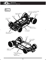
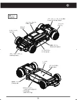
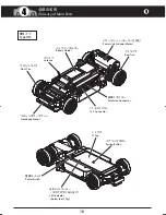
Page 13: ...vehicle Compatible with body for type 1 chassis Light weight and low CG characteristics allow superior turning abilities ムービングシャシーは大きく分けて13 16ページのように2種類のメインフレームと 3種類のモーターケースに分かれています お手持ちのシャシータイプをご確認ください タイプ2専用ボディ以外が搭載可能です 軽量 低重心でコーナーリング性能に 優れています タイプ 2 Type 2 Compatible with all types of body shells 全てのボディが搭載可能です Illustration from here will show type 1 as an example 以降のイラストは全てタイプ1ですがタイプ2も同様です ...

Page 14: ...クター Extension Connector Power Unit Includes Motor Power Switch Front Body Mount フロントボディマウント I C S Connector I C Sコネクター I C Tag I C タグ Pairing Button ペアリングボタン LED Indicator below the IC Tag LEDインジケーター ICタグの下にあります Antenna アンテナ Battery Holder バッテリーホルダー 4 Glossary of Main Parts 各部の名称 ...

Page 15: ... Rear Tire 拡張コネクター Extension Connector Power Switch Front Body Mount フロントボディマウント I C S Connector I C Sコネクター I C Tag I C タグ Pairing Button ペアリングボタン LEDインジケーター ICタグの下にあります Antenna アンテナ Battery Holder バッテリーホルダー Power Unit Includes Motor LED Indicator below the IC Tag 4 ...

Page 16: ...ター Extension Connector Power Switch Front Body Mount フロントボディマウント I C S Connector I C Sコネクター I C Tag I C タグ Pairing Button ペアリングボタン LEDインジケーター ICタグの下にあります Antenna アンテナ Battery Holder バッテリーホルダー Power Unit Includes Motor LED Indicator below the IC Tag 4 4 Glossary of Main Parts 各部の名称 ...

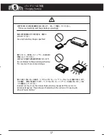
Page 17: ...s may cause fire or serious damage 誤った取り扱いをした場合 リチウムポリマーバッテリーがふくらむ場合があります この場合 非常に危険ですので リチウムポリマーバッテリーの処分のしかた に従 って処理をしてください Incorrect use may cause the Lithium Polymer battery to expand If this occurs it is extremely dangerous Please dispose of according to the section on Disposing of a Lithium Polymer Battery 安全のための注意事項を良く読んで 正しく充電してください Please read carefully and charge battery accordingly ...

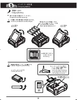
Page 18: ...単3型アルカリ乾電池 又は ニッケル水素バッテリー 4本 1 2 動作確認用LEDランプ Charge battery before operating Insert AA size batteries into the charger Open cover Close cover AA size alkaline or Nickel Metal Hydride batteries x 4 Connect charger to special battery Insert with battery label facing up and align battery terminals with the charger terminals Remove battery cover Function Indicator LED 5 Charging Battery バッテリーの充電 ...

Page 19: ...he LED is still green Do not use the battery If the battery is fully charged and the LED is off charging will stop If the LED shows Green Red AA batteries are out of power Replace the AA size batteries If the LED is red error the battery is not functioning normally e g voltage If this occurs the circuit protection is activated and charging will stop For batteries that haven t been used for a long ...

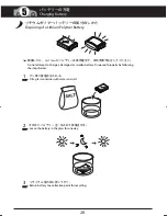
Page 20: ...empt to charge a damaged or swollen battery Dispose of properly by following the steps below ビン等に食塩水を入れる その中にバッテリーを一日入れて放電させる リサイクル協力店に持って行く Fill a glass container with water and salt Leave the battery in the glass for one day Return battery to a collection point for recycling 3 2 1 5 Charging Battery バッテリーの充電 ...

Page 21: ...ase button and remove the battery box Be careful not to drop the batteries リリースボタンを押してバッテリーボックスを取出す バッテリーボックスを落とさないように注意する Insert the Battery Box all the way unti you hear it click in Make sure the Battery Box is locked in バッテリーボックスを奥まで差し込み カチッと音がして バッテリーボックスがロックされたことを確認する AAA Alkaline Dry Batteries 4 pieces 単4型アルカリ乾電池 4本 Note the direction 向きに注意 2 3 4 1 ...

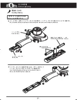
Page 22: ...す A 1 2 3 Try not to grip sharp edges or windows on the body too tightly This can cause injury or damage Use a 0 or 1 screwdriver The included screwdriver cannot be used Remove the Auto Scale Collection s acrylic case While holding the body use a screw driver to remove screw then remove pedestal and chassis mounting part Use both thumbs to spread the A body sections then use both index fingers to ...

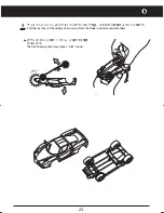
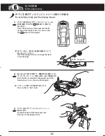
Page 23: ...フロント部が パチン と音がする場合 があります ディスプレイシャシーのリヤタイヤとボディのリヤ部を それぞれ引き離すようにして取外す 4 パチン The front body section may make a click sound Pull the rear tires of the display chassis away from the body in order to separate them 6 ...

Page 24: ...hing body and the display chassis Insert the 凸 section of the body into the 凹 section of the display chassis as shown with the outline in the diagram Insert the display chassis at an angle of about 30 to the body With the chassis inserted in the groove push the display chassis in as shown in the diagram You may hear a click noise Spread the sides of the body apart and attach on to the display chas...

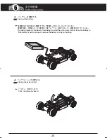
Page 25: ...プ1 約20 タイプ2 約90 2 1 2 6 Before Operating 走行の準備 approx 20 約20 Installing battery onto the moving chassis Make sure the moving chassis power is switched OFF Open the battery hatch by pulling back the lip of the battery hatch Be careful not to open the battery hatch too wide Battery hatch should only be opened type 1 about 20 and type 2 about 90 ...

Page 26: ...再度取付けてください パチン と音がします 3 4 Connect the battery Closing the battery hatch The design prevents the battery from being inserted the wrong way Not not force the battery in If the battery is hard to connect remove the battery and try re inserting Click sound can be heard 6 Before Operating 走行の準備 ...

Page 27: ...い Attaching body to the moving chassis Try not to grip sharp edges or windows on the body too tightly This can cause injury or damage Align the A section of the front body mount on the moving chassis to the B section on the front of the body as per the diagram Align moving chassis and body at a right angle as per the diagram Pivot the body down to cover the moving chassis Spread the body and attac...

Page 28: ...s dNaNo it must undergo a pairing adjustment 初めてお買い上げ頂いた車体 dNaNo を使用する場合には ペアリングという設定が必要です Antenna アンテナを立てる お買い上げ頂いた車体に使用する送信機のIDを記憶させる作業のことです 使用する送信機を変更する場合 にもペアリングを行ってください 車体と送信機をその組み合せで使用する 最初の1回目だけに行います Pairing is the process of registering the transmitter s ID with your chassis If you change transmitters please perform pairing Pairing process is not required after the first time What is pairi...

Page 29: ...he LED indicator light has dimmed the preparation of the transmitter is complete LEDが先程より暗く点灯したら 送信機側の準備は完了 Prepare Tool A and locate the LED indicator and pairing button LED indicator is below the IC Tag ツールAを用意し ペアリングボタン LEDインジケーターの場所を確認する LEDインジケーターはICタグの下に あります 3 3 Confirm the LED is on When the LED goes out after about 3 seconds release finger from the Throttle Trim LEDインジケーターが点灯しているのを確認する 約3...

Page 30: ...ジケーターを確認する 点灯 正常にペアリングが完了 点滅 ペアリング失敗 送信機 車体の電源を切って ペアリングをやり直す 3 Once the LED indicator comes on stop pushing the Pairing Button LEDインジケーターが点灯したら ペアリングボタン を押すのをやめる 4 LED Indicator will show the following Light is ON Pairing has been successful Light is flashing Pairing has not be completed Switch the transmitter and chassis power off and do pairing again 7 Click sound can be heard カチッ と音がします ...

Page 31: ... pairing at the same time Complete pairing at another time Another 2 4GHz device is being used close by Stop using wireless LAN or Bluetooth devices Appliances such as a microwave oven are emitting strong electrical waves close by Stop using the electrical appliance Another radio control model using 2 4GHz is being used close by Perform pairing in another location 7 Let s Drive 走行させましょう If Pairing...

Page 32: ...n the transmitter finds open frequencies Up to forty dNaNo FX Series models can be run but may be lower if other 2 4GHz devices are being used If no frequency can be found LED will not light Operate in another location この時に送信機は周りの電波をスキャンして 空いている周波数を見つけます dNaNo FX シリーズは同時に最大40台まで走行 できますが その他の2 4GHz帯の電波を使用する電子機器が近くにある場合には 同時走行できる台数は40台よりも少なくなります また 空き電波が見つからない場合には LEDインジケーターが点灯しません 走行させる場所を変えてお楽しみくだ...

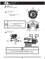
Page 33: ...beep stops Adjustment not needed if car doesn t move Beeping sound will start when neutral is found or range limit is reached スロットルトリガーを中立に保ち 車体が止まるようにスロットルトリムをクリックして調整します 車体から ピー という音が出なくなるように調整します 電源を入れた時に車体が止まっている場合には 調整の必要はありません 操作は1クリックずつ行います 押しっぱなしにしても動きません スロットルトリムが中立の時には ピピピ と音がします 調整範囲が限界になった場合にも ピピピ と音がします If chassis is moving in reverse click this button 車体が後進してしまう時はこちらのボタンをクリックする A A B...

Page 34: ...How to Control Your Model Basic Controls Raise the tires off the ground and check that all controls are responding Throttle Trigger スロットルトリガー 中立 前進 Forward Neutral 後進 Reverse ブレーキ Brake 1 2 全てのタイヤを浮かせた状態で操作と動きを確認してください Raise the tires off the ground and check that all controls are responding Forward Reverse 前進 後進 7 Let s Drive 走行させましょう ...

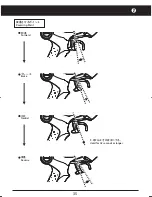
Page 35: ...35 Reversing Point 後進させるポイント Forward 前進 Brake ブレーキ Neutral 中立 Hold for 0 2 seconds or longer 0 2秒以上そのままにする Reverse 後進 7 ...

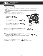
Page 36: ... B Check if a continuous beep sound is coming from the chasis 車体から ピー という音が出ているかどうか確認する If no sound 音が出ていない Refer へ Problems with Reversing うまくバックできない時は When Throttle Trigger is in neutral and the car hasn t stopped moving follow the steps below to adjust neutral position スロットルトリガーが中立の時に 車体が正しく停止状態になっていません 下記の手順で中立の 調整をします 1 2 2 Refer へ 2 2 Refer へ 3 3 Refer へ 3 3 Refer へ 4 4 Beep sound but car is...

Page 37: ...しても動きません If chassis moves left L click Steering Trim to adjust 車体がLの方向へ行く場合には ステアリングトリムの をクリックして調整します R R R L If chassis moves right R click Steering Trim to adjust 車体がRの方向へ行く場合には ステアリングトリムの をクリックして調整します L L When steering trim is in neutral or adjustment has reached the end of its range beeping sound will start ステアリングトリムが中立の時には ピピピ と音がします 調整範囲が限界になった場合にも ピピピ と音がします Due to effects from steering mec...

Page 38: ...g Response You can adjust the steering angle the degree to which tires turn to your liking ステアリングの舵角 タイヤの切れる量 を好みに合わせ調整します Adjust left and right steering angles separately ステアリングの舵角は 左右別々に調整します Once adjustment range has been reached beeping will sound 調整範囲が限界になった場合には ピピピ と音がします 7 Let s Drive 走行させましょう ...

Page 39: ...ングトリム を押す 2 R R Push Steering Trim ステアリングトリム を押す L L Turn steering wheel all the way to the left and hold ステアリングホイールを左一杯まで切る そのまま保持 Increases angle 舵角が増す To adjust left steering angle 左の舵角を調整する場合 1 Push Steering Trim ステアリングトリム を押す 2 L L Decreases angle 舵角が減る Decreases angle 舵角が減る Push Steering Trim ステアリングトリム を押す R R Steering Trim ステアリングトリム Steering Trim ステアリングトリム R L R L 7 ...

Page 40: ... dNaNo FXシリーズの車体は 電池残量が少なくなるとオートカット機能が働き 車体が停止します この場合はすぐに使用をやめて バッテリーを充電するか別の充電済みバッテリーに交換してください オートカット機能が作動した状態で電源のON OFFを繰り返すとバッテリーが使用できなくなります When speed drops noticeably replace the batteries スピードが遅くなったと感じたら電池を 交換してください If a dNaNo FX Series car runs low on power the auto cut off is activated and the car will stop If this occurs stop using immediately and recharge or replace the batteries If aut...

Page 41: ...41 電源の切り方 送信機側の電源スイッチを切る 車体側の電源スイッチを切る Transmitter Switch Chassis Switch Switching Power OFF 1 2 電源を切るときは必ず車体側からスイッチを切ってください When switching power OFF always switch car OFF first 7 ...

Page 42: ...l throttle timing will be reached faster 前進時にスロットルが全開になるタイミングが 早くなります 1 Click Throttle Trim スロットルトリム をクリックします 2 A A Forward full throttle timing will be reached slower Full throttle will not be reached 前進時にスロットルが全開になるタイミングが遅くなります 全開にならなくなります Click Throttle Trim スロットルトリム をクリックします B B Throttle Range Adjustment スロットル開度の調整 Beeping sound will start when maximum adjustment range has been reached 調整範囲が限界...

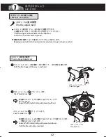
Page 43: ...ecomes slower ブレーキが弱くなります 後進が遅くなります 1 Click Throttle Trim スロットルトリム をクリックします 2 A A Braking becomes stronger Reverse full throttle timing becomes earlier ブレーキが強くなります 後進で全開になるタイミングが早くなります Click Throttle Trim スロットルトリム をクリックします B B Brake Power Adjustment ブレーキの強さの調整 Throttle Trim スロットルトリム Throttle Trigger スロットルトリガー A B 7 ...

Page 44: ...h power OFF 電源を切ります 1 Switch power ON 電源を入れます 3 LED indicator flashes to indicate training mode is active LEDインジケーターが早く点滅して トレーニング モードであることを知らせます 4 Move Throttle Trigger all the way to reverse position and hold スロットルトリガーを後進側一杯に操作して その状態を保ちます 2 Setting Training Mode トレーニングモードに設定する LEDインジケーター LED Indicator Throttle Trigger スロットルトリガー 7 Let s Drive 走行させましょう ...

Page 45: ...3 seconds Release Throttle Trim 更にスロットルトリム を押し続け 約3秒後に LEDインジケーターが点灯するのを確認したら スロットルトリム からすぐに指を離します 2 Switch power OFF 電源を切ります 1 Switch power ON 電源を入れます 3 If LED indicator lights up normal mode is active LEDインジケーターが点灯していれば 通常モードに 戻っています 4 Pull Throttle Trigger in all the way and hold スロットルトリガーを前進側一杯に操作して その状態を保ちます 2 Returning to Normal Mode 通常モード ノーマルモード に戻す Throttle Trim スロットルトリム B B B B B B LEDイン...

Page 46: ...erating Tips Hold your elbows in and keep the transmitter antenna pointing straight up Training Mode is recommended for first time users of the dNaNo Squeeze the throttle trigger gently and steer the car to left and right Squeeze the throttle trigger gently and release Repeat this motion to control speed If you are unsure of the steering practice holding the transmitter with the steering wheel fac...

Page 47: ...い 8の字走行で練習を積みましょう 5 6 7 8 Refer to P37 to reduce the amount of steering angle for first time use Be careful not to squeeze the throttle trigger abruptly while steering After you become used to the controls experiment with the high performance possible at full throttle and full steering Practice doing figure 8s Click クリック Steering Trim ステアリングトリム 8 ...

Page 48: ...48 Replacement for Tires タイヤの交換 9 各部の交換 Replacement for Each Part ボディを取外してから作業を行ってください ホイールからタイヤを取外して交換してください Remove the body before doing any work Remove tires from the wheels then replace ...

Page 49: ...は ムービングシャシーを横に立てて タイヤ ホイール をしっかり持って行ってください Attaching screws to the included screwdriver or a magnetized screwdriver before screwing them in is recommended Insert the 凹 section of the wheel into the 凸 section ofthe wheel hub and fasten in place with screw Insert the 凹 section of the wheel into the 凸 section ofthe wheel hub and fasten in place with screw Position the moving chassis on its side and h...

Page 50: ... ボディ バッテリーを取外してから作業を行ってください ツールAを用いてコネクターを抜き モーターの配線を外してください How to remove the Motor モーターの取外し Tool A ツールA 1 1 3 2 Remove the body and battery before starting work Use Tool A to detach the connectors and remove motor wiring 9 各部の交換 Replacement for Each Part ...

Page 51: ... Chassis HMタイプシャシー HM Type Chassis 右リヤタイヤの脱着 Wheel Screw ホイールビス Rear Tire リヤタイヤ Wheel Screw ホイールビス Rear Tire リヤタイヤ Wheel Screw ホイールビス Wheel Screw ホイールビス Refer to Replacing Wheels on page 48 of the instruction manual for removing attaching tires Fitting Right Rear Tire Screw Hexagon Head 1 x 2 5mm ビス 六角頭 1 9 ...

Page 52: ...opper モーターストッパー モーターストッパー モーターストッパー Fitting Motor Stopper モーターストッパーの脱着 1 2x3 5mm 1 2x3 5mm 1 2x3 5mm MMタイプシャシー MM Type Chassis RMタイプシャシー RM Type Chassis HMタイプシャシー HM Type Chassis When attaching the motor stopper always check the motor wires before tightening the screws モーターストッパーを取付ける際は モーターコードの配線を必ずチェックしてから ビス止めしてください TP Screw 1 2 x 3 5mm TPビス 2 9 各部の交換 Replacement for Each Part ...

Page 53: ...tting the Eccentric Adjuster エキセントリックアジャスターの脱着 モーターが取出せない場合は配線などが引っかかっていないか確認してください Do not pull the motor wiring This may result in the wires breaking If not removing the motor make sure the wires are not caught 組み立てるときは55ページに従ってエキセントリックアジャスターの調整をしてください When assembling the chassis refer to P 55 for adjusting the Eccentric Adjuster MMタイプシャシー MM Type Chassis RMタイプシャシー RM Type Chassis HMタイプシャシー HM Ty...

Page 54: ...ントリックアジャスターにモーターを取付ける際の注意 エキセントリックアジャスターの凸部にモーターの凹部をはめ込み モーターコードを図のように 配線してください Eccentric Adjuster Precautions when attaching the motor to the eccentric adjuster Insert the 凸 section of the eccentric adjuster into the 凹 section of the motor and arrange the motor wires as per the diagram below 9 各部の交換 Replacement for Each Part ...

Page 55: ...t be used Too much load on the motor can damage or break the motor 8Tピニオンギヤではリヤタイヤのホイール径が 19R以上 9Tピニオンギヤではリヤタイヤの ホイール径が18R以上のものは使用できません モーターへの負荷が大きくなり故障や破損の 原因となります 6T 7T 8T 9T Pinion Gear Max Speed Acceleration RunningTime Long ピニオンギヤ 最高速 加速 Good 良い 走行時間 長い Fast 速い Remove the Pinion Gear ピニオンギヤを抜く Set pinion gear in Tool D ピニオンギヤをツールDにセットする Install the Pinion Gear ピニオンギヤを入れる ギヤ比表 Gear Ratio Table...

Page 56: ... 9T MMタイプシャシー MM Type Chassis RM Type Chassis HM Type Chassis Adjust the backlash space between the pinion gear and spur gear by turning the eccentric adjuster according to the scale on the motor stopper Check you chassis type and pinion gear before adjusting When the rotation of the Eccentric Adjuster seems tight slightly loosen the Motor Stopper Screw Adjusting Backlash 9 各部の交換 Replacement for E...

Page 57: ...itive is Red モーターコード赤 Make sure the motor wires do not interfere with the tires gears or body モーターコードがタイヤ ギヤ ボディなどに干渉しないように注意してください Connect the wires as shown in the drawing コードは図のように収納してください Negative is Black Positive is Red モーターコード赤 モーターコード黒 MMタイプシャシー MM Type Chassis RMタイプシャシー RM Type Chassis HMタイプシャシー HM Type Chassis 9 ...

Page 58: ...mum scale realism each Dnano chassis has its own detailed settings for the height wheelbase etc can be adjusted to change the overall chassis type To change the chassis type to suit different Auto Scale Collection bodies the Fitting Parts Set is required The Fitting Parts Set includes the parts required for each chassis type Go to the website below to download the option parts list and check the i...

Page 59: ...automatically starts external setting mode Settings include steering servo power speed range and drive frequency of the motor control amp This receiver is the first RC to be equipped with an interactive data communication function with a personal computer This enables machine settings to be done externally through the computer I C S 受信機をはじめとする R C機器が通信機能を持ち 機器間またはパソコンとの通信が 出来る様になります 通信により機器の設定を外部で...

Page 60: ...ュニティ レース タイムアタックなどへの参加が 可能になります About the IC Tag ICタグについて The memory records data according to ID and therefore recognizes the unique ID of each moving chassis The special scan system enables connection to the latest lap time count systems Connect to a network to share with the user community races and time attack を随時ご確認ください これらの機能を利用し 様々な遊びの形態を京商は提供していきます 今後の展開にご期待ください Check regularly for news Us...

Page 61: ...N019 DN009 DN001 DN009 DN023 DN019 DN008 DN008 DN019 DN019 DN019 DN015 DN012 DN012 フロント部用 For Front メーカー指定の純正部品を使用して 安全にR Cを楽しみましょう OP OP No Description 品番 パーツ名 210 一律 税込 定価 税込 発送 手数料 スペアパーツ Spare Parts DN019 DN020 Screw Set M1x2 5 20pcs Screw Set M1 2x3 5 20pcs Silver ビスセット M1x2 5 20pcs ビスセット M1 2x3 5 20pcs シルバー 473 9975 DNW102 420 DN001 DN023 DN012 DN006 DN016 Main Frame Assembly Plastic Bushing...

Page 62: ... MM dNaNoモーター エキセントリックアジャスター デフギヤ アッセンブリー 品番 パーツ名 788 420 788 945 578 210 一律 税込 定価 税込 発送 手数料 DN019 DN012 Plastic Bushing Set DN008 Pinion Gear Set プラメタルセット ピニオンギヤセット DN020 DN020 DN020 DN020 スペアパーツ Spare Parts DN002 DN012 DN012 DN007 DN018 DN002 DN005 DN019 B DN017 DN008 DN018 m g g h k m k c 473 315 473 Screw Set M1x2 5 20pcs Screw Set M1 2x3 5 20pcs Silver ビスセット M1x2 5 20pcs ビスセット M1 2x3 5 20pcs ...

Page 63: ...リックアジャスター デフギヤアッセンブリー 品番 パーツ名 788 420 315 788 945 473 578 473 Wheel Screw Set 6pcs Black ホイールビスセット 6pcs ブラック 210 一律 税込 定価 税込 発送 手数料 DN019 DN012 Plastic Bushing Set DN008 Pinion Gear Set プラメタルセット ピニオンギヤセット スペアパーツ Spare Parts DN017 DN020 DN020 DN020 DN020 DN003 DN012 DN012 DN007 DN018 DN003 DN005 DN019 B DN018 m k i g g h DN008 k m Eccentric Adjuster Screw Set M1x2 5 20pcs Screw Set M1 2x3 5 20pcs S...

Page 64: ...ーターケース HM dNaNoモーター エキセントリックアジャスター デフギヤアッセンブリー 品番 パーツ名 788 420 315 788 945 473 578 473 210 一律 税込 定価 税込 発送 手数料 DN019 DN012 Plastic Bushing Set DN008 Pinion Gear Set プラメタルセット ピニオンギヤセット スペアパーツ Spare Parts DN020 DN020 DN020 DN020 DN004 DN012 DN012 DN007 DN018 DN018 DN004 DN005 DN019 B DN017 m k i g g h k m Wheel Screw Set 6pcs Black ホイールビスセット 6pcs ブラック Screw Set M1x2 5 20pcs Screw Set M1 2x3 5 20pcs S...

Page 65: ...Steering Trim is not adjusted correctly Front Wheels vibrate side to side Main road or large steel pylon is nearby Batteries have run low Batteries have run low オートカット機能が作動している 39ページ The Auto cut off is activated Refer to P39 オートカット機能が作動している 39ページ The Auto cut off is activated Refer to P39 Polarity or battery type is wrong ペアリングが解除されてしまった Transmitter or chassis power switch is not ON Turn the powe...

Page 66: ...00 京商株式会社 Hereby KYOSHO CORPORATION declare that this product is in compliance with the essential requirements and other relevant provisions of Directive 1999 5 EC The Declaration of Conformity DoC can be downloaded at following URL http www kyosho com web download index e html dNaNoホームページ www dnano jp 68 ...

Reviews: