23
・
Never connect the signals to reserve pin.
・
Arrange an external power supply for relay drive.
In addition, pay attention to the capacity of the external power.
・
To connect a relay to control output, add a diode in parallel to the coil of a relay.
Absence of a diode can cause damage.
・
Insert a surge killer in the contact of a relay.
For detailed information about a surge killer, contact the manufacture of a relay in use.
・
For connecting more than 1-m long cable, use a twisted cable.
・
For connecting more than 3-m long cable, use a shielded cable and always ground the shielded cable to
the ground terminal.
・
In addition, for connecting more than 30-m long cable or using outdoors, take special countermeasures
against noise.
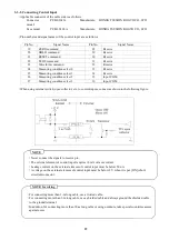
3-3-3. Connecting Control Output
・
The control output signal is open collector output and sink type.
・
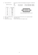
Applicable connector of the cable side is as same as that of the control input side.
・
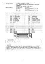
Pin numbers and signal names of the control output are as follows.
Pin No.
Signal Name
Pin No.
Signal Name
1
HH comparator output
10
SD
2
HI comparator output
11
Reserve
3
OK comparator output
12
Reserve
4
LO comparator output
13
Reserve
5
LL comparator output
14
Reserve
6
Abnormal channel
15
Reserve
7
Abnormal memory
16
Reserve
8
Communication error
17
Output COM
9
Healthy
18
Output COM
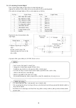
・
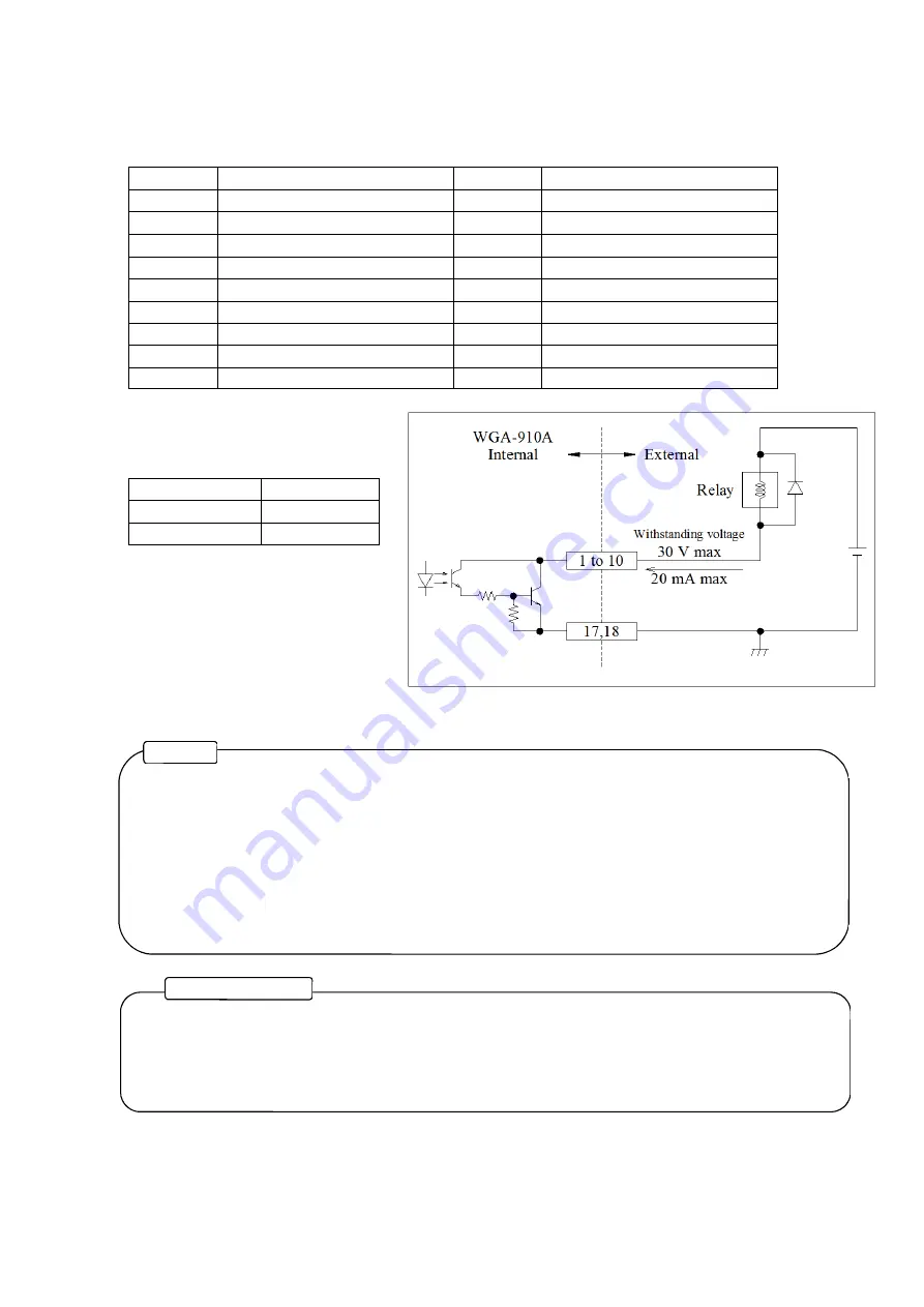
Equivalent circuit is described as the
right figure.
Output Signal
Transistor
0
ON
1
OFF
* Suppose output logic is “Negative
logic.”
For the “positive logic,” the
transistor output is reverse of the
above table.
・
Capacity of the open collector is 30 VDC, 20 mA or less.
NOTE for wiring
NOTE

