STRATUS Multi-Deck Display Case
11
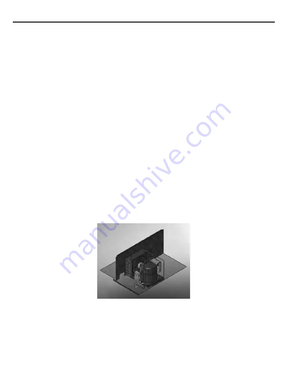
Modular Condensing Unit
Mounting Base and Enclosure
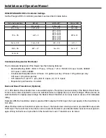
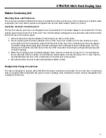
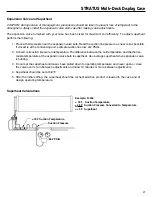
The control box and Buck & Boost transformer are attached to the top of the case. The condensing unit, defrost water
evaporation pan and valance panels are shipped loose and are field installed. (Refer to pictures)
Assembly—Modular Condensing Unit
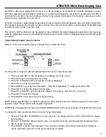
The top front valence pan
el has a rectangular knock out provided for the controller display to be inserted into. The top
valence panel must face the front of the case. The controller display rectangular knockout will be located at the bottom
left front corner of the valence panel.
1.
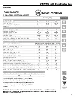
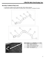
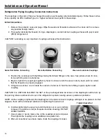
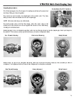
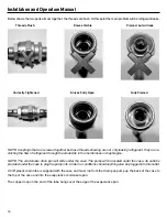
All the components must be installed in the locations as shown in the photo.
2. The condensing unit must be positioned on top of the case in the position so that the condenser coil fac
-
es the right end of the case when viewed from the front of the case. The condensing unit must be aligned
so that the refrigeration piping quick connect couplings can be attached to the condensing unit The con-
densing unit should be screwed down to the top of the case after connecting the refrigeration piping quick
connect couplings.
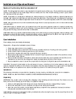
3. When the condensing unit is installed properly, there must be a minimum air gap of 12” or more between
the air inlet side of the condenser coil and the end valance panel. A minimum space of 5” or more must be
provided between the rear of the condensing unit and the rear valance panel.
4. All electrical wires must be routed inside flexible metallic conduit.
Refrigeration Piping Connections
This case is designed to operate with a 208-230 Volt single condensing unit located on top of the case. Condensing
units are supplied with refrigeration line quick connect couplings. (See installation of quick connect refrigeration line
coupling for reference).

