background image

28 


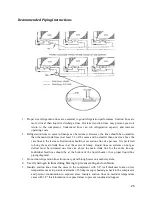
Do  not  place  product  in  cases  until  it is at proper  operating  temperature.  Air discharge  and return  flues 
must  remain  open  and  free  of  debris  or  obstruction  at  all  times  to  provide  proper  refrigeration  and  air 
current performance. Do not allow any product, signs, debris, etc. to block these grilles. Do not use any 
non-approved shelving, display racks or any accessory that could hamper air current performance.
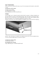
 

WARNING!


Do not walk on top of the cases!

 This could result in damage to the case and serious 

personal  injury  could  occur. These  cases are  not  designed  to  support  excessive  external  weight.  Do  not 
use top of cases for storage. 
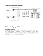
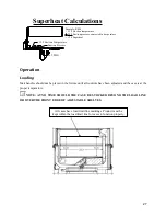
Normal Operation 

Below are the different operation methods for our cases. Cases vary depending on application and how 
they were specifically ordered. Review the data plate on your cases and refer to the Case Data previously 
listed in this manual for your models specific information. 

1.


Off-Cycle Defrost. The fans run continuously and defrost termination is by termination Klixon.  

2.


Electric Defrost models are optional. Electric heaters are utilized to melt the frost and ice on the 

coil. The  heaters  are located  in the  air  stream  in  front  of  the  coil. The  defrost  cycle  is time 
initiated and should be temperature terminated. Case fans operate continuously in defrost and 
refrigeration.  As  a  safety  precaution,  a  safety  cutoff  Klixon  is  wired  in  this  series  with  the 
defrost heater set to turn the heater off at temperatures above 70°F.  

3.


Hot  Gas  Defrost  models  are  optional  for  parallel  compressor  operation  only.  Hot  gas  is  routed 

through  the  suction  line  and  evaporator  coil.  It  exits  the  coil  through  a  by-pass  around  the 
expansion  valve  and  heat  exchanger,  in  order  to  return  to  the  liquid  line.  The  condensed 
liquid is then used to feed the other cases on the parallel case. The display case’ fans continue 
to operate during defrost to warm up the drain pan and air ducts. The defrost cycle is time-
initiated and should be temperature terminated.  

4.


Single Condensing Case Systems. A thermostat should be used to control case temperatures. The 

thermostat bulb should be mounted in the discharge air. 


NOTE

: Heat exchangers are standard in hot gas defrost models. They aid in increasing operating 

efficiency and reducing frosting and flood-back to the compressor. Heat exchangers may not be used if 
mechanical subcooling is incorporated in the system design. 

Cleaning 

As  a  general  rule, always use  mild soap  and  water to  wipe  the  case down.  Special  precautions  must  be 
taken when cleaning some components of the case. 
Exterior surfaces should be cleaned with warm water and mild soap to protect and maintain the finish. 

Do 

not  use  cleaners  containing  abrasive  materials  or  ammonia,  which  will  scratch  or  dull  the  finish.


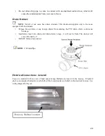
The waste outlet should be flushed with water following each cleaning. 
Interior surfaces may be cleaned with most  mild soap formulas, as well as ammonia based cleaners and 
sanitizing solutions. These cleansers should not harm the interios surface. 


WARNING!

  Always  shut  power  off  during  the  cleaning  process.  Cleaning  the  case  with 

electrical power applied is a shock hazard that may cause serious injury or death. 

Summary of Contents for QILG 06

Page 1: ... Installation Operation Manual QILG Island Display Case IMPORTANT KEEP IN STORE FOR FUTURE USE 5 52 20 01 1 T Tr ra an ns sp po or rt t B Bo ou ul le ev va ar rd d C Co ol lu um mb bu us s G GA A 3 31 19 90 07 7 7 70 06 6 5 56 68 8 1 15 51 14 4 ...

Page 2: ...2 ...

Page 3: ...12 Joining Instructions 12 Installation of Trim Caps Shelves 13 Case Front Part Selection 14 Case Trim Selection 15 Canopy 15 Front Rail Alignment 16 3 Bumper 16 Raceway Cap 16 Glass Cap Rail End Trim Installation Glass Models 17 Rear Cap Joint Trim Installation 17 Bumper Rub Rail Cap and Raceway Cover Installation 18 Rub Rail Cap 18 Waste Outlet Drip Pipe Description and Location 19 Drain Straine...

Page 4: ...ssembly 29 Parts List and Drawings 30 Warranty 32 One Year Warranty 32 Parts Warranty Policy 33 New Equipment Parts Shortages and Defects 33 Parts Ordering Procedure 33 Return Authorization Procedure 33 Contact Information 36 ...

Page 5: ...ment should be examined for shipping damage before and during unloading If there is any damage the carrier should be notified immediately and an inspection requested The delivery receipt must be noted that the equipment was received damaged If damage is of a concealed nature you must contact the carrier within three 3 days following delivery The consignee must file a claim with the carrier NOTE Al...

Page 6: ...ves are available depending on end user refrigerant requirements Expansion valves are supplied for the refrigerant specified on the original sales order In addition cases can be modified in the field to allow changing the type of refrigerant used This requires changing the expansion valve and distributor orifice that is currently equipped in the case Contact your Kysor Warren Service Representativ...

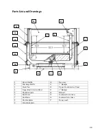
Page 7: ...7 Plan View and Cross Sections QILG Cross Section ...

Page 8: ...8 QILG Plan View ...

Page 9: ... 15 F 11 F 175 FPM 8 2600 2540 2480 12 3900 3810 3720 Refrigeration Data Dairy Food Length ft BTUH Fan Motors Evaporator Temperature Discharge Air STD PSC ECM Temperature Velocity 1 hr after defrost 6 1425 1365 1305 24 F 30 F 175 FPM 8 1900 1840 1780 12 2850 2760 2670 Electrical Data Length ft Fan Motor Heaters STD PSC ECM Electric Defrost Optional 230V Anti Sweat Drain Pan Heater Electric Defrost...

Page 10: ...ll Q case models Electric defrost and hot gas defrost are available for installations requiring a positive defrost CAUTION Failure to maintain maximum design conditions may result in operational issues such as increased BTU load high product temperature coil icing product frosting and external sweating CAUTION Failure to properly install electrical wiring and control wiring as per wiring diagram s...

Page 11: ...erational checkout procedures following the instructions within this manual CAUTION Be careful not to damage the factory installed end while moving the case Use the case lift points on the case to move it to the proper location Installing First Case 1 Ensure all preparation for installation as outlined in the above paragraphs have been fully complied with and are complete 2 If multiple cases are t...

Page 12: ... order lineup sticker found on the fan plenum or door and on the back panel of the case 2 Remove skids and shipping braces 3 Ensure all case expansion valves are correct 4 Do not install electrical drain lines or refrigerant lines until all the cases have been set placed into position and properly leveled 5 Do not install case trim ends or caps until all cases have been set into position and prope...

Page 13: ...using pry bar 3 Inspect joint for proper air and watertight seal inside and outside the case 4 Replace lineup access cover plugs and plates 5 Move cases as close together as possible and level by using the shims provided same as original case Use shelf standard struts for alignment to be sure cases are level CASES MUST BE LEVELED FROM FRONT TO BACK END TO END AND SUPPORTED CONTINUOUSLY AS NEEDED W...

Page 14: ...up 3 McCue Bumper Starter 1 lineup Rub Rail Cap 1 case Std or w ptm Raceway Cap 1 case 1 McCue Bumper 1 case 3 McCue Bumper 1 case For Single Case Rub Rail Cap 1 case Std or w ptm Raceway Cap 1 case 1 McCue Bumper 1 case 3 McCue Bumper 1 case Canopy End Trim 2 lineup Glass Cap End Trim 2 lineup Glass Cap Joint Trim 1 joint Front Panel End Trim 2 lineup ...

Page 15: ...anopy It may be necessary to loosen and or remove the screws at the top of the canopy to aid in the alignment of the two canopies and to eliminate any gap between the canopies The screws should be tightened after canopies are aligned Align the case front rails with a single alignment pin sliding the pin across the joint into the adjoining front rail It may be necessary to loosen the screws holding...

Page 16: ...he screws holding the front rail to aid in the alignment process The screws should be tightened after the front rails are aligned 3 Bumper Install the 3 bumper parts to the raceway using the same procedure as described for the 1 bumper parts Raceway Cap Install the raceway cap parts to the raceway using the same procedure as described for the rub rail cap NOTE The raceway cover parts do not overla...

Page 17: ... lineup and remove the screws from the rear cap Rotate the rear cap forward the alignment pins will hold it in place and position the trim as shown in the illustration Slide the trim across the case joint under the rear cap of the adjoining case about half the width of the trim Rotate the rear cap back into place over the trim and secure the rear cap and screw cover Repeat this procedure for each ...

Page 18: ...p Rub Rail Cap Install the four foot rub rail cap to the left hand of the first case in the lineup To install the rub rail cap hook the lower edge of the cap to the aluminum front rail just above the 1 bumper On non glass models rotate the cap toward the case and snap the cap onto the back hook of the aluminum front rail For glass models rotate the cap toward the case and snap the cap onto the top...

Page 19: ...n NOTE Improperly installed drip pipes can seriously effect the operation of this case and result in increased maintenance costs Listed below are some general rules for drip pipe installation Never use a double water seal Never use a pipe smaller than the size pipe or water seal supplied with the case Always provide as much fall as possible in drip pipe 1 fall for each 4 of drip pipe Avoid long ru...

Page 20: ...oreign objects from entering the PVC drain which could cause blockage Installation Insert into drain until drain strainer stops it will not be flush The strainer will exceed the hub by 1 DO NOT flatten drain strainer NOTE 1 Drain Pipe Electrical Connections General Cases are standard with one row of high output lamps Ballasts are located in the raceway If lighted shelves are supplied ballasts for ...

Page 21: ...not dislodged NOTE The fluorescent bulb is capable of lighting even if the bulb and shelf power cord are not completely seated WARNING Ensure the Kick plate does not come in contact with the case electrical wiring Live electrical wiring that comes in contact with the case is a shock hazard that may cause severe injury or death by electrocution WARNING Always disconnect the electrical power at the ...

Page 22: ...mponent Wire Number Anti Sweat Heater 1 and 2 Refrigerator Fan Motors and Drain Heater 3 and 4 Lighting Circuit 5 and 6 Defrost Heaters 7 and 8 Temperature Control 9 and 10 Dual Temperature 15 and 16 Defrost Termination Control 17 and 18 All electrical connections are made in the electrical raceway ...

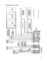
Page 23: ...23 Wiring Diagram Per Side ...

Page 24: ... all four corners All refrigeration lines need to be as close to the drain pan as possible so as not to obstruct the air pattern or block the deck pans After refrigeration lines have been connected and pressure tested fill case pipe penetration with spray foam Let spray foam dry cut excess foam flush with inside of case bottom and then add a layer of silicone sealant for a water tight seal ...

Page 25: ... preferred to bring the main trunk lines in at the center of lineup Liquid lines on systems on hot gas defrost must be increased one line size above the main trunk line for the entire line up Individual feed lines should be at the bottom of the liquid header See proper liquid line piping diagram 3 Do not run refrigeration lines from one system through cases on another system 4 Use dry nitrogen in ...

Page 26: ...re drop in the suction lines 15 When connecting more than one suction line to a main trunk line connect each branch with an inverted trap 16 Suction Lines a Should be pitched in the direction of flow b Should enter at the top of the branch line c May be reduced by one size at 1 3 of case run load and after 2 3 of case run load DO NOT reduce below the case suction line size Expansion Valve and Supe...

Page 27: ...at Operation Loading Merchandise should not be placed in the fixture until all controls have been adjusted and the case is at the proper temperature NOTE AT NO TIME SHOULD THE CASE BE STOCKED BEYOND THE LOAD LINE OR OVER THE FRONT EDGE OF ADJUSTABLE SHELVES All cases have load limit line markings Product must be kept within the load limit line for cases to function properly ...

Page 28: ...as Defrost models are optional for parallel compressor operation only Hot gas is routed through the suction line and evaporator coil It exits the coil through a by pass around the expansion valve and heat exchanger in order to return to the liquid line The condensed liquid is then used to feed the other cases on the parallel case The display case fans continue to operate during defrost to warm up ...

Page 29: ...ng solutions and even water are allowed to come in contact with them Every precaution should be made to keep liquids away from the coated side of the mirrors If liquids are allowed to flow along the face side of the mirror to its edge the liquid can seep between the coating and the glass causing serious damage To help prolong the life of the mirrors Use only mild cleaning solutions Windex Solox or...

Page 30: ... Bumper 3 Deck Pan 12 Upper Front Exterior Panel 4 Upper Rear Exterior Panel 13 1 Bumper 5 Rear Kickplate 14 Rubrail 6 Fan Motor 15 Insulated Front Glass 7 Fan Blade 16 Insulated Side Glass 8 End Kickplate 17 Honeycomb 9 Front Kickplate 16 17 1 2 3 4 5 6 7 8 9 10 11 12 13 14 15 ...

Page 31: ...10K10127 2 Fan Wiring Harness 2 fan 10M10151 Fan Wiring Harness 3 fan 10M10148 2 2 Fan Wiring Harness 4 fan 10M10152 Deck Pan PTD 54N18287 6 8 12 Deck Pan BRT 55M16059 6 8 12 Deck Pan PTD end case 54N18567 Deck Pan BRT end case 55M16158 Honeycomb White 13A15133 2 4 6 Honeycomb Black 13A15134 2 4 6 Honeycomb White 13A15137 Honeycomb Black 13A15138 NOTE The above diagram and list of parts is a compl...

Page 32: ...g the manufacturer s brand name Thermopane Twindow etc the manufacturer s glazing warranty in effect at the time of this shipment is extended to that assembly It is void outside the continental United States II BULBS Light bulbs and fluorescent lamp tubes are not covered by any warranty for length of life or for any type of breakage III THIS WARRANTY SHALL NOT APPLY 1 To the condensing case used w...

Page 33: ... Kysor Warren no more than 10 working days from the date of delivery After this time has expired Kysor Warren will assume the parts were lost during installation and all parts required will be charged cost plus shipping to replace Parts Ordering Procedure All parts must be ordered through the Kysor Warren parts department with the following information Store Name and Number Location Case or Case M...

Page 34: ...34 ...

Page 35: ...35 ...

Page 36: ...a 31907 706 568 1514 Telephone 1 800 866 5596 Email solutions kysorwarren com Website http www kysorwarren com Kysor Warren whose policy is one of continuous improvement reserves the right to change at anytime these specifications designs or prices without incurring obligation ...

Reviews: