12
8.
Connect water drain line. Reference waste outlet (drip pipe) description and location
procedure.
9.
Connect input AC power. Reference the electrical installation procedure later in this manual.
10.
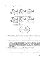
Connect refrigerant lines. Reference the procedure later in this manual.
11.
Install all ends, caps, and trim per the applicable instructions contained in this manual.
12.
Remove shipping tape on fluorescent lamps (if applicable) and remove all other shipping
material.
13.
Refer to the operational start up procedures later in this manual. If multiple cases are to be
installed, refer to the following paragraph for installing subsequent cases.
Installing Subsequent Cases
If additional cases are to be installed, follow the same procedures as described in the installing first case
procedure (above), in addition to the following:
1.
Move cases as near their permanent location as possible before removing shipping braces, skids
or rollers.
NOTE
: All cases are factory numbered with lineup and position numbers. Make sure that cases are
installed in order (lineup sticker found on the fan plenum or door and on the back panel of the case).
2.
Remove skids and shipping braces.
3.
Ensure all case expansion valves are correct.
4.
Do not install electrical, drain lines, or refrigerant lines until all the cases have been set/placed
into position and properly leveled.
5.
Do not install case trim, ends, or caps until all cases have been set into position and properly
positioned and leveled.
6.
Before lining up cases use the front and rear edges as a baseline to inspect refrigeration lines,
electrical connections and controls, and to insure cases are in proper lineup and are in proper
sequence.
7.
Remove shipping tape on fluorescent lamps (if applicable) and remove all other shipping
material. Follow all joining instructions listed below to connect cases in a lineup.
Joining Instructions
Two or more cases of like models can be joined together to form a continuous lineup. Before lining up
cases, inspect refrigeration lines, electrical connections and controls to insure cases are in the proper
lineup and sequence. Reference and become familiar with the below figure, then join the cases using the
instructions that follow.
Lineup Bolt Holes on the Side of the Cases - See Caulking Diagram Below
Summary of Contents for QILG 06
Page 2: ...2 ...
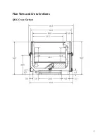
Page 7: ...7 Plan View and Cross Sections QILG Cross Section ...
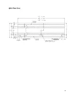
Page 8: ...8 QILG Plan View ...
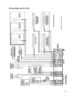
Page 23: ...23 Wiring Diagram Per Side ...
Page 34: ...34 ...
Page 35: ...35 ...

